Journal of Power and Energy Engineering, 2015, 3, 194-199
Published Online April 2015 in SciRes. http://www.scirp.org/journal/jpee
http://dx.doi.org/10.4236/jpee.2015.34027
How to cite this paper: Yi, Z., Wang, J.G., Fan, Y.D., Zhou, M. and Cai, L. (2015) Grounding Impedance Measurement of High
Speed Railway Integrated Grounding System. Journal of Power and Energy Engineering, 3, 194-199.
http://dx.doi.org/10.4236/jpee.2015.34027
Grounding Impedance Measurement of High
Speed Railway Integrated Grounding System
Zhang Yi, Jianguo Wang, Yadong Fan, Mi Zhou, Li Cai
School of Electrical Engineering, Wuhan University, Wuhan, China
Email: yitiaxiao@163.com, wjg@whu.edu.cn, ydfan@whu.edu.cn, zhoumi927@163.com, caili@whu.edu.cn
Received January 2015
Abstract
The high-speed railway integrated grounding system is the basic guarantee for the safe and stable
operation of the railway. It is the worlds largest long-distance horizontally elongated joint groun-
ding system, which stretches the length of hundreds to thousands of kilometers, and its structure
is not only different from power station and substation grounding system, but also different from
the transmission line tower, lightning rod and other small grounding devices. There is little re-
search information on the grounding impedance of high-speed railway integrated grounding sys-
tem. This paper adopted 0.618 compensation method and reverse away method respectively,
measured a section of high-speed railway integrated grounding system grounding impedance by
JD16 and CA6425. Measurement results are in good agreement using those two type instrument.
By using 0.618 compensation method, the measurement result will be gradually converged at 0.3
Ω with the increasing of current electrode distance, which is the real grounding impedance of in-
tegrated grounding system. By using reverse away method, the maximum measurement result
difference is less than 0.024 Ω with the lead of current electrode distance increasing. The mea-
surement results will be rapidly converged 0.25 Ω. The results showed that the reverse away me-
thod is helpful to shorten the length of current electrode wiring. The measurement error will be
small when the current electrode wiring is longer.
Keywords
High-Speed Railway, Integrated Grounding System, Grounding Impedance
1. Introduction
Over the past few years, China has invested a lot of manpower and material resources in the development and
construction of high speed railway, whose operation speed has been improved to 350 km/h in service. In order to
reduce the potential difference and electromagnetic interference between each professional system, high-speed
railway in China have adopted the integrated grounding system [1]-[4]. By laying the run-through ground wire
along the two sides of railway, high-speed railway integrated grounding system fuses traction power supply re-
turn system, power service system, communication signal system, buildings, road bed, platform, bridges, tunnels,
sound barrier and other electrical and electronic information system together, forming a huge-scale long-dis -
tance horizontal grounding system, which is the basic guarantee and important measure to maintain high speed
Z. Yi et al.
195
railway safe and reliable operation, ensure operating personnel and electrical equipment safety.
At present, the domestic and foreign research and analysis about the grounding performance of grounding
body have been quite comprehensive, but they mainly focused in the power system grounding. Railway inte-
grated grounding system is a longitudinal through large horizontal grounding body, whose structure is not only
different from power station and substation grounding system, but also different from the transmission line
tower, lightning rod and other small grounding devices. Many existing research results of power system groun-
ding body can not be directly applied to the railway integrated grounding field. High-speed railway integrated
grounding system is a new grounding body, little information is about it, whose grounding impedance characte-
ristics need to be deeply studied.
This paper respectively adopted 0.618 compensation method and reverse away method, measured a section of
high -speed railway integrated grounding system grounding impedance [5] [6]. The results showed that the re-
verse away method is helpful to shorten the length of current electrode wiring.
2. Grounding Impedance Measurement of High-Speed Integrated Grounding
System
2.1. Measurement Method
Figure 1 is the 0.618 compensation method measurement schematic diagram, where the voltage electrode dis-
tance dPG between the voltage electrode P and the integrated grounding system equals to 0.618 the current elec-
trode distance dCG, dCG is the distance between the current electrode C and the integrated grounding system. The
current electrode C, the voltage electrode P and the current injected point G are in a straight line as shown in
Figure 1.
Figure 2 is the reverse away method measurement schematic diagram, where the voltage electrode distance
dPG1 = 0.5 dCG. The straight line dCG and the straight line dPG1 are the same straight line as shown in Figure 2.
These straight line are perpendicular to the railway integrated grounding system. The current and potential
testing circuit can be accurately set by the global positioning system (GPS).
2.2. Measurement Position and Measurement Instrument
This paper carried out the comparison of grounding impedance measurement between the 0.618 compensation
method and reverse away method in plain embankment section of uniform soil resistivity in Wuhan-Guangzhou
high -speed railway section DK1274.331. The width of run-through ground wire of railway integrated grounding
system is about 26 m. The current injection point is in the leading out terminal of integrated grounding wire in
the right of railway cable trench, as shown in Figure 3.
The measuring instrument is four terminal grounding resistance tester, as shown in Figure 4. There are JD16-
type grounding resistance tester (Hereinafter referred to as the JD16) and digital grounding resistance meter
Figure 1. 0.618 compensation method.
d
PG
d
CG
G
P
C
Railway integrated grounding system
Z. Yi et al.
196
Figure 2. Reverse away method.
Figure 3. Field test images.
dPG1
dCG
G
P
C
Railway integrated grounding system
G1
Z. Yi et al.
197
(a)
(b)
Figure 4. Measurement instrument. (a) JD 16. (b) CA6425.
(hereinafter referred to as the CA6425).
JD16 are tested with the test current 47.5 Hz and 52.5 Hz, reading the average test results. It measured groun-
ding impedance Z and its real part R and imaginary part of X, whose measurement range of grounding imped-
ance is 0 - 30 kΩ, and measurement error is less than 1%. CA6425 measured grounding impedance, soil resistiv-
ity and electrical integrity, and its measurement range is 0 - 1999 Ω, accuracy is 2%, the resolution is 0.01 Ω.
3. Measurement Results
0.618 Compensation Method Measurement Results
0.618 compensation method measurement results of railway integrated grounding system's grounding imped-
ance are shown in Figure 5. As you can see from Figure 5, JD16 and CA6425 measurement results are in good
agreement, the maximum measurement result difference is less than 0.04 Ω. With the lead of current electrode
distance increasing, the measurement results will be gradually converged at 0.3 Ω which is the real grounding
impendence of integrated grounding system.
When the current electrode wiring dCG is 36 m, measurement result using JD16 is 0.783 Ω. When the current
Z. Yi et al.
198
electrode wiring dCG is 266 m, measurement result using JD16 is 0.342 Ω. When the current electrode wiring
dCG is 710 m, measurement result using JD16 is 0.285 Ω. By JD16 measurement difference of current electrode
wiring between 430 m and 710 m is less than 0.016 Ω. The current electrode distance increase is helpful to get
the small measurement error.
Reverse away method measurement results of railway integrated grounding systems grounding impedance
are shown in Figure 6. As you can see from Figure 6, JD16 and CA6425 measurement results are in good
agreement, the maximum measurement result difference is less than 0.024 Ω. With the lead of current electrode
distance increasing, the measurement results will be rapidly converged.
When the current electrode wiring distance of reverse away method measurement railway integrated groun-
ding systems grounding impedance is above 100 m, the difference is less than 0.01 Ω.
4. Discussion
The 0.618 compensation method measurement results with short current electrode wiring are bigger. The longer
current electrode wiring can reduce the error brought by the zero potential point, and the measurement results
are beginning to converge. The increased current electrode wiring length facilitates the convergence measure
Figure 5. 0.618 compensation method measurement results.
Figure 6. Reverse away method measurement results.
0
0.1
0.2
0.3
0.4
0.5
0.6
0.7
0.8
0.9
0100 200 300 400 500 600 700 800
grounding impedance (Ω)
current elctrode distancem
JD16
CA6425
0
0.1
0.2
0.3
0.4
0.5
0.6
0.7
0.8
0.9
0100 200 300 400 500 600 700 800 900
grounding impedance(Ω)
current electrode distancem
JD16
CA6425
Z. Yi et al.
199
ment results when the compensation method is used.
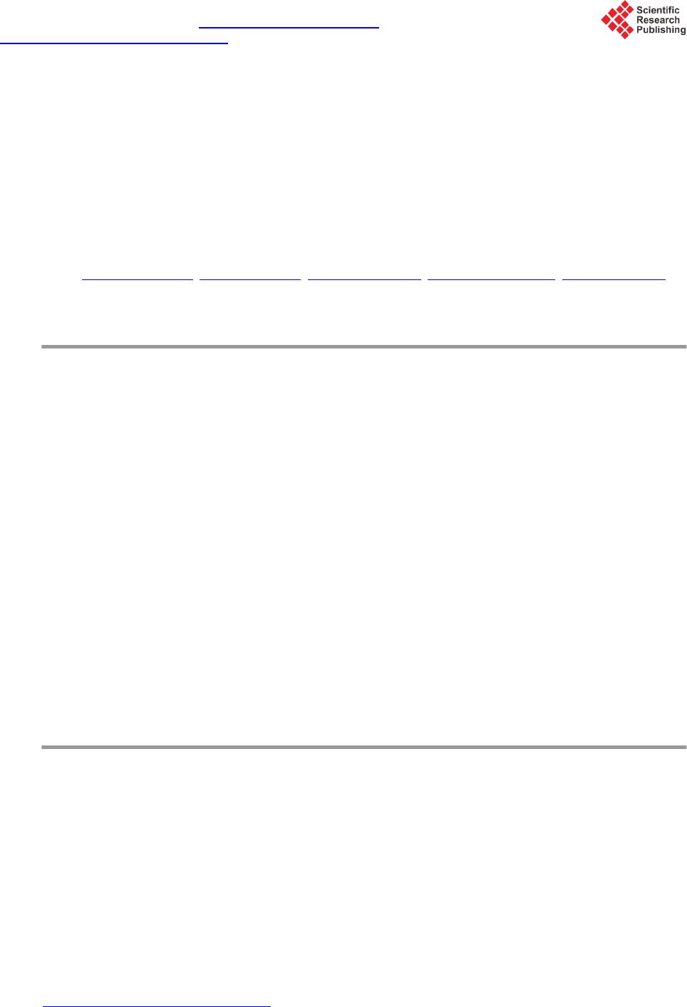
The 0.618 compensation method in the theoretical is taking the 0.5 current electrode length as the zero poten-
tial point, through potential compensation to realize the inherent error compensation of the voltage electrode po-
sition. Compared to railway integrated grounding system of long distance run-through grounding wire, the cur-
rent electrode is very small vertical grounding electrode. The current field distribution distortion is serious when
the current electrode wiring is short. The zero potential position has big error, The error will be small when the
current electrode wiring is longer.
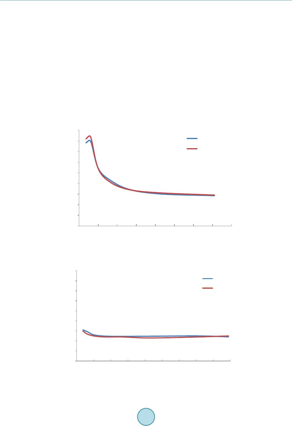
When the current electrode wiring is 36 m, the measurement result of reverse away method is 0.31 Ω. While
the current electrode wiring is 430 m, the measurement result of compensation method is 0.301 Ω. When the
current electrode wiring is 60 m, the measurement result of reverse away method is 0.294 Ω. While the current
electrode wiring is 710 m, the measurement result of compensation method is 0.29 Ω. The measurement results
of the two methods are almost the same.
When the current electrode wiring is the same, compared to the compensation method, the measurement result
of the reverse away method converges quickly. The reverse away method is helpful to reduce the current elec-
trode wiring.
But the measurement result of the reverse away method is smaller than the measurement result of the com-
pensation method, which is similar to [7]. The amendment will be completed in the future work.
5. Conclusions
This paper respectively adopted 0.618 compensation method and reverse away method by two types of instru-
ments, and measured a section of high-speed railway integrated grounding system grounding impedance.
1) Measurement results are in good agreement using the two types of instruments by using 0.618 compensa-
tion method and reverse away method.
2) By using 0.618 compensation method, the measurement result will be gradually converged at 0.3 Ω. By
using reverse away method, the measurement results will be rapidly converged 0.25 Ω. Convergence rate of re-
verse away method is quicker than 0.618 compensation method.
3) The measurement result of the reverse away method is smaller than the measurement result of the 0.618
compensation method, so amendment will be considered in the future work.
4) Reverse away method is helpful to shorten the length of current electrode wiring.
References
[1] Wu, G.N., Gao, G.Q., Dong, A.P., et al. (2011) Study on the Performance of Integrated Grounding Line in High-Speed
Railway. IEEE Transactions on Power Delivery, 26, 1803-1810. http://dx.doi.org/10.1109/TPWRD.2011.2117446
[2] Pan, R., Wu, M.L. and Yang, S.B. (2009) Performance of the IGS of Hefei-Nanjing Passenger Dedicated Railway.
Proc. Int. Conf. Sustainable Power Generation and Supply, 1-5.
[3] Natarajan, R., Imece, A.F., Popoff, J., et al. (2001) Analysis of Grounding Systems for Electric Traction. IEEE Trans-
actions on Power Delivery, 16, 389-393. http://dx.doi.org/10.1109/61.924816
[4] Mariscotti, A., Pozzobon, P. and Vanti, M. (2005) Distribution of the Traction Return Current in AT Electric Railway
Systems. IEEE Transactions on Power Delivery, 20, 2119-2128. http://dx.doi.org/10.1109/TPWRD.2005.848721
[5] IEEE Standard No.80-2000 (2000) IEEE Guide for Safety in AC Substation Grounding.
[6] ANSI/IEEE Std. 81 (20 12 ) Guide for Measuring Earth Resistivity, Ground Impedance, and Earth Surface Potentials of
a Ground Syst em.
[7] Wang, C., Takasima, T., Sakuta, T., et al. (1998 ) Grounding Resistance Measurement using Fal l-of-Potential Method
with Potential Probe Located in Opposite Direction to the Current Prob e. IEEE Transactions on Power Delivery, 13,
1128-1135. http://dx.doi.org/10.1109/61.714472