 Int. J. Communications, Network and System Sciences, 2015, 8, 79-84 Published Online April 2015 in SciRes. http://www.scirp.org/journal/ijcns http://dx.doi.org/10.4236/ijcns.2015.84010 How to cite this paper: Wei, L.X., Zeng, X.Q. and Shen, T. (2015) A Wireless Solution for Train Switchgear Contact Temper- ature Monitoring and Alarming System Based on Wireless Communication Technology. Int. J. Communications, Network and System Sciences, 8, 79-84. http://dx.doi.org/10.4236/ijcns.2015.84010 A Wireless Solution for Train Switchgear Contact Temperature Monitoring and Alarming System Based on Wireless Communication Technology Lexiang Wei, Xiaoqing Zeng, Tuo Shen School of Transportation Engineering, Tongji University, Shanghai, China Email: wlx_1022@qq.com, zengxq@tongji.edu.cn, st8250@163.com Received March 2015 Abstract We present a temperature monitoring and warning system, which is based on wireless communi- cation technology and applied in train switchgear in this paper. The system is consists of three parts, including wireless temperature detection module, inter-vehicle transmission networks module and remote monitoring server. The switchgear contact temperature data are collected via the wireless temperature detection module and exchanged in inter-vehicle wireless networking by Zigbee modules. Then the temperature of train switchgear cabinets can be monitored remotely through the GPRS wireless communication. Keywords Train Switchgear, Wireless, Temperature Monitoring, Communication Technology 1. Introduction On the train, switchgear is relatively fragmented distributed, and the internal overheating switchgear in use is important problem due to the switching cabinet loose connection or airtight. The traditional artificial tempera- ture measuring method in the daily train maintenance is complicated, and temperature data cannot be collected real-time, it is very difficult to find out the hidden danger, and it will make the train in dangerous status and threat to the passengers’ safety. According to the special environment of the train, choose a reasonable solution to solve this problem is nec- essarily. Wireless sensor network technologies have been applied in industrial control widely. Its advantages in- clude the liability, simplicity, and low cost in both installation and maintenance [1]. Through the wireless tem- perature detection method, Zigbee network technique, and GPRS communication technique, a system which can collect all the switchgear contact temperature data on the train, transmit data between each carriages, and trans- mit all data to a remote monitoring server be designed. In the current study, we present the framework and function of system, explain its principle and key tech- 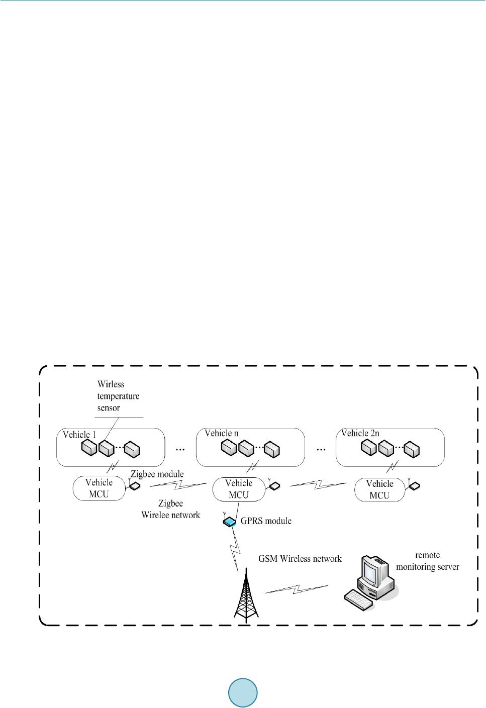 L. X. Wei et al. niques, and the hardware and software design of the system also be given in this paper. 2. System Architecture The train switchgear contact temperature monitoring and alarming system based on communication technology is composed of wireless temperature detection module, inter-vehicle transmission networks, and remote moni- toring server. The system structure is shown in Figure 1. Wireless temperature detection module is consist of several wireless temperature sensors, each wireless tem- perature sensor detect a switchgear contact temperature. Inter-train transmission networks is a network which can share the data of each carriage switchgear contact temperature, since the train is divided into several carriage, it is necessary to organize a data-share network, so that the system can collect the data of whole train switchgear contact temperature. Then the system transmits the native data to remote monitoring server by GPRS module. Remote monitoring server is used to save historical temperature data, display train switchgear contact temper- ature, and analyze the temperature data. Remote monitoring server provides sound & light alarm when the tem- perature data reach the alarm value. 3. The Hardware of System 3.1. Wireless Temperature Sensors Wireless temperature sensors are based on zigbee technology, they work on frequency of 2.4 GHz with applica- tion IEEE802.15.4 wireless communication protocol [2] [3]. The modulation method of the module is direct se- quence spread spectrum (DSSS). Wireless temperature sensors use the LTCC built-in antenna, and its transmis- sion power is less than 10 mw. As shown in Figure 2, Wireless temperature sensors integrates several parts, such as temperature sensor, measuring circuit, logic control circuit, wireless circuit, and power supply circuit. 3.2. Inter-Train Transmission Networks Because each carriage has the characteristic of separation, which directly restricts the ways of communication Figure 1. System structure.  L. X. Wei et al. Figure 2. Wireless temperature sensor. between each two carriages, wire transmission cannot adapt to the special environment. According to the com- parison of zigbee, wifi and Bluetooth, as shown in Table 1. [4] [5], we choose zigbee to establish train wireless transmission network, Zigbee is a kind of low complexity, low power consumption, low data rate and low cost of wireless personal area network technology [6]. Sinem Coleri Ergen summarized three types of topologies of Zigbee: star topology, cluster tree topology and peer-to-peer topology [7]. According to the different characteristics of Zigbee network topology, we choose peer-to-peer topology to establish the train wireless transmission networks, and the peer to peer network topol- ogy is shown in Figure 3. Zigbee network equipments are divided into three types. The first kind of equipments is called the terminal equipment (End Device). The structure and function of end device is the simplest, they work at sleep mode in most of the time to maximum saving the electric energy and extending the life of battery. Another kind of equipments is the router node, it can store and retransmission data. The top level in the network structure is PAN coordinator. Except for some functions of router. It also can make rules of network, choose the right channel and start the PAN etc. As shown in Figure 4, train wireless transmission network is consisted of a Central Coordinator node and several Router nodes. The Central Coordinator node is located in the middle carriage of the train, and Router nodes distribute at other carriages. The Central Coordinator node, which is the core of the transmission network, broadcast the message to the Router nodes nearby, then, Router nodes will send the message to other Router nodes in the same network. In this way, all the nodes can share data through this Train wireless transmission network. The MCU (main control circuit) of single node in train wireless transmission network is shown in Figure 5, we choose a high performance processor named ARM STM32F103RCT6 to be the processor in our circuit, we also use watch dog to protect the system. LCD touch screen is used to show real-time data. We choose a flash memory chip called M25P16 to save temperature data on the train. 4. The Software of System The software of system includes wireless temperature sensor software, Inter-train transmission sub-system soft- ware and remote monitoring software three parts. 4.1. Wireless Temperature Sensor Software Wireless temperature sensor works at the mode of dormancy mechanism. After power on the sensor, the module will complete the initialization, then, the timer start time and the sensor enter the sleep mode automatically. The timer will generate an interrupt to wake up system to read the temperature data 60 seconds per time. After Wire- less temperature sensor gets the temperature data, it will upload the data to Inter-vehicle transmission sub-sys- tem through RS-232 serial port. 4.2. Inter-Train Transmission Sub-System Software Inter-train transmission sub-system has following tasks: (1) collect the temperature data from wireless tempera- Wireless temperature sensor temperature sensor measuring circuit Zigbee wireless module power supply circuit logic control circuit 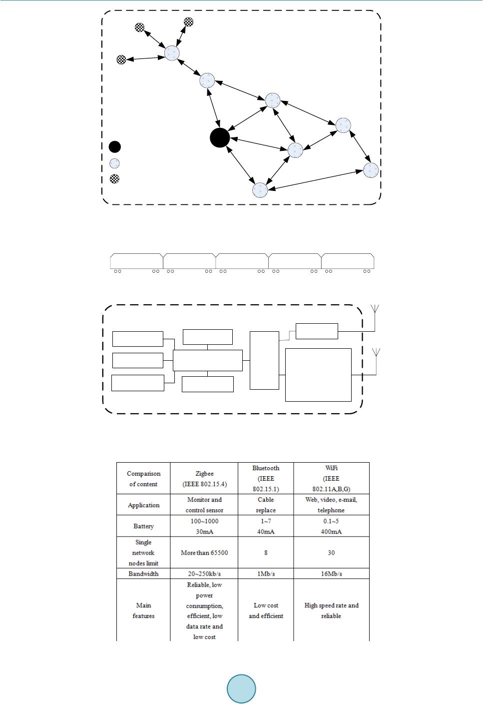 L. X. Wei et al. Figure 3. Peer to peer network topology. Figure 4. Train wireless transmission network. Figure 5. The MCU circuit of node in train wireless transmission network. Table 1. Comparison of Zigbee, Bluetooth and WiFi. PAN coordinator Router node End device Central Coordinator node Router nodeRouter nodeRouter nodeRouter node...... MCU (STM32F103RCT6) LCD touch screen Flash memory circuit Power supply circuit Watch dog circuit Click circuit Driver circuit Zigbee circuit GPRS circuit (only Central Coordinator node) 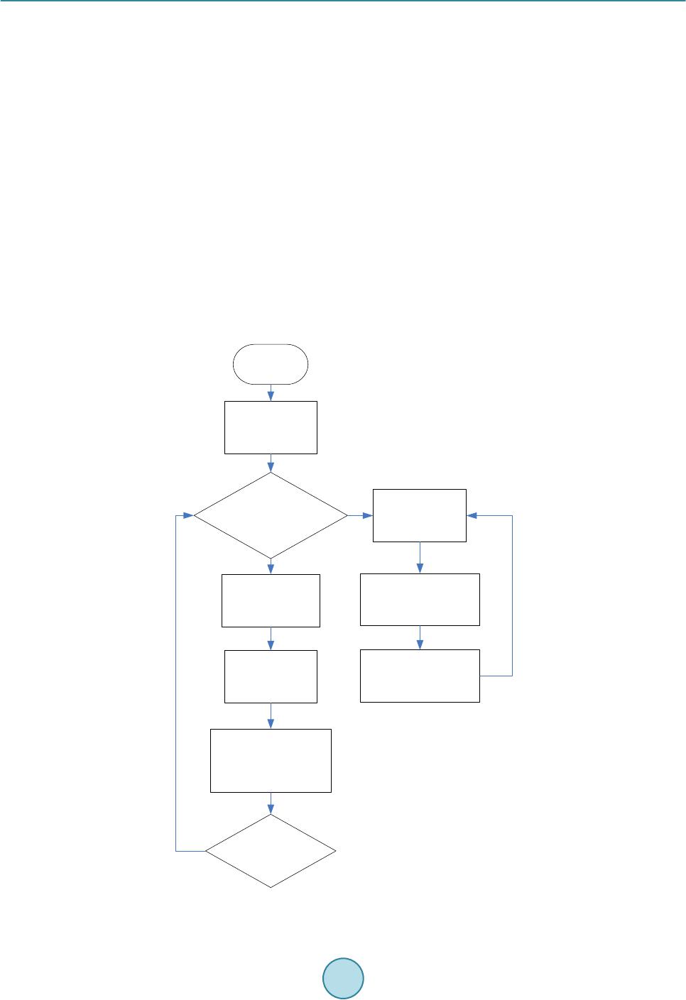 L. X. Wei et al. ture sensors in its carriage; (2) If the node is Central Coordinator node, the inter-train transmission sub-system will ask other Router nodes for the temperature data of other carriages, then send all the data to remote monitor- ing server; (3) receive message from other Inter-train transmission sub-systems, and deal the message according to the protocol. The logic of Inter-train transmission sub-system is shown in Figure 6. The program will complete the first in- itialization after power on. Then the MCU of the system will read the node message from native storage. In or- der to prevent the accident error, the software be designed as “three choose two” redundancy processing. System will work choose to work in different mode according to the message, if the system is a Central Coordinator node, it will broadcast the message to ask other nodes for temperature data 50 seconds per time, then upload the temperature data of all train to remote monitoring server through GPRS module. 4.3. Remote Monitoring Software Remote monitoring software includes the backstage database and the management website two parts, after re- ceive the data from train, system save the data at the database, then refresh the display on the screen of PC. Management website has following functions, such as train the current temperature data display, curve trend diagram display, data record, data statistics display and the alarm log. If any switch contact temperature reaches the alarm temperature, remote monitoring software will create sound & light alarm. Through the website, man- ager can know all the temperature data on the train real-time. Figure 6. The logic of inter-train transmission sub-syst e m. Start If the node is a Central Coordinator node yes Ask other carriages temperature data Collect native temperature data Send all train temperature data to remote monitoring server no Collect native temperature data Receive the order from Central Coordinator node broadcast the message to Central Coordinator node Complete the operation yes initial  L. X. Wei et al. 5. Conclusion In this study, we discussed the wireless solution for train switchgear contact temperature monitoring and alarm- ing system based on wireless communication technology and designed the structure, hardware and software of the system. This system can monitor the train switchgear contact temperature in real-time remotely, through it, we can improve the efficiency of train maintenance work, enhance the capacity of train fault early warning and have a positive significance to the safe operation of train. Acknowledgements This work was supported by the project of Shanghai Science and Technology Commission (No.12231200103). References [1] Zhang, Q., Yang, X.-L., Zhou, Y.-M., Wang, L.-R. and Guo, X.-S. (2007) A Wireless Solution for Greenhouse Moni- toring and Control System Based on ZigBee Technology. Journal of Zhejiang University Science A, 8. [2] Ascariz, J.M.R. and Boquete, L. (2007) System for Measuring Power Supply Parameters with ZigBee Connectivity. Instrumentation and Measurement Technology Conference Proceedings, IMTC 2007, 1-5. http://dx.doi.org/10.1109/IMTC.2007.379344 [3] Alliance, Z. (2006) ZigBee Specification. ZigBee Document 053474r13. [4] (2013) Communication Sys t em . Electronic Industry Press. [5] Fang, M., Wan, J. and Xu, X. (2008) A Preemptive Distributed Address Assignment Mechanism for Wireless Sensor Networks. 4th IEEE International Conference on Wireless Communications, Networking and Mobile Computing, Da- lian. http://dx.doi.org/10.1109/WiCom.2008.827 [6] Saito, T., Tomoda, L., Takabatake, Y., Ami, J. and Teramoto, K. (2000) Home Gateway Architecture and Its Imple- mentation. IEEE International Conference on Consumer Electronics, 194-195. [7] (2004) Sinem Coleri Ergen. ZigBee/IEEE802.15.4 Summary. www.eecs.berkley.edu/~csinem/acadernic/publicatious/
|