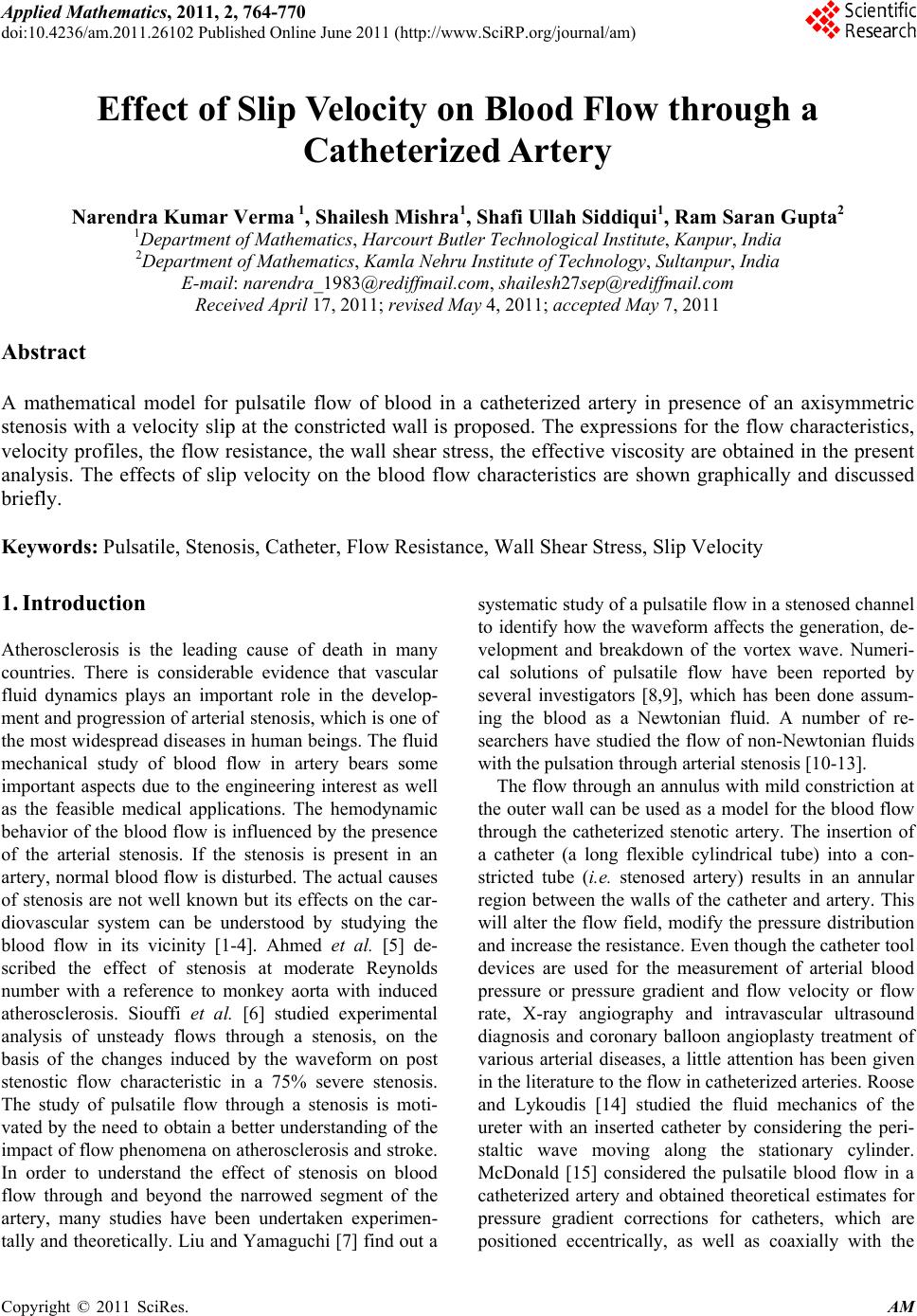
 Applied Mathematics, 2011, 2, 764-770 doi:10.4236/am.2011.26102 Published Online June 2011 (http://www.SciRP.org/journal/am) Copyright © 2011 SciRes. AM Effect of Slip Velocity on Blood Flow through a Catheterized Artery Narendra Kumar Verma 1, Shailesh Mishra1, Shafi Ullah Siddiqui1, Ram Saran Gupta2 1Department of Mat hem at i cs, Harcourt Butler Technological Institute, Kanpur, In di a 2Department of Mat hem at i cs, Kamla Nehru Institute of Technology, Sultanpur, India E-mail: narendra_1983@rediffmail.com, shailesh27sep@rediffmail.com Received April 17, 2011; revised May 4, 2011; accepted May 7, 2011 Abstract A mathematical model for pulsatile flow of blood in a catheterized artery in presence of an axisymmetric stenosis with a velocity slip at the constricted wall is proposed. The expressions for the flow characteristics, velocity profiles, the flow resistance, the wall shear stress, the effective viscosity are obtained in the present analysis. The effects of slip velocity on the blood flow characteristics are shown graphically and discussed briefly. Keywords: Pulsatile, Stenosis, Catheter, Flow Resistance, Wall Shear Stress, Slip Velocity 1. Introduction Atherosclerosis is the leading cause of death in many countries. There is considerable evidence that vascular fluid dynamics plays an important role in the develop- ment and progression of arterial stenosis, which is one of the most widespread diseases in human beings. The fluid mechanical study of blood flow in artery bears some important aspects due to the engineering interest as well as the feasible medical applications. The hemodynamic behavior of the blood flow is influenced by the presence of the arterial stenosis. If the stenosis is present in an artery, normal blood flow is disturbed. The actual causes of stenosis are not well known but its effects on the car- diovascular system can be understood by studying the blood flow in its vicinity [1-4]. Ahmed et al. [5] de- scribed the effect of stenosis at moderate Reynolds number with a reference to monkey aorta with induced atherosclerosis. Siouffi et al. [6] studied experimental analysis of unsteady flows through a stenosis, on the basis of the changes induced by the waveform on post stenostic flow characteristic in a 75% severe stenosis. The study of pulsatile flow through a stenosis is moti- vated by the need to obtain a better understanding of the impact of flow phenomena on atherosclerosis and stroke. In order to understand the effect of stenosis on blood flow through and beyond the narrowed segment of the artery, many studies have been undertaken experimen- tally and theoretically. Liu and Yamaguchi [7] find out a systematic study of a pulsatile flow in a stenosed channel to identify how the waveform affects the generation, de- velopment and breakdown of the vortex wave. Numeri- cal solutions of pulsatile flow have been reported by several investigators [8,9], which has been done assum- ing the blood as a Newtonian fluid. A number of re- searchers have studied the flow of non-Newtonian fluids with the pulsation through arterial stenosis [10-13]. The flow through an annulus with mild constriction at the outer wall can be used as a model for the blood flow through the catheterized stenotic artery. The insertion of a catheter (a long flexible cylindrical tube) into a con- stricted tube (i.e. stenosed artery) results in an annular region between the walls of the catheter and artery. This will alter the flow field, modify the pressure distribution and increase the resistance. Even though the catheter tool devices are used for the measurement of arterial blood pressure or pressure gradient and flow velocity or flow rate, X-ray angiography and intravascular ultrasound diagnosis and coronary balloon angioplasty treatment of various arterial diseases, a little attention has been given in the literature to the flow in catheterized arteries. Roose and Lykoudis [14] studied the fluid mechanics of the ureter with an inserted catheter by considering the peri- staltic wave moving along the stationary cylinder. McDonald [15] considered the pulsatile blood flow in a catheterized artery and obtained theoretical estimates for pressure gradient corrections for catheters, which are positioned eccentrically, as well as coaxially with the  N. K. VERMA ET AL.765 artery. The effect of catheterization on various flow characteristics in an artery with or without stenosis was studied by Karahalios [16]. Dash et al. [17] considered the steady and pulsatile flow of the Casson fluid in a nar- row artery when a catheter is inserted into it and esti- mated the increase in frictional resistance in the artery due to catheterization. In view of the discussions given above the present work is devoted to study the pulsatile flow of blood through a catheterized artery in presence of an axi-symmetric stenosis with a velocity slip at the con- stricted wall. The theoretical model used here enables one to observe the effects of slip velocity on resistance to flow, the wall shear stress distribution in the stenotic region, and the effective viscosity. To neglect the en- trance, end and special wall effects, the artery length is assumed large enough as compared to its radius. 2. Mathematical Formulation Consider an axially symmetric, laminar, pulsatile and fully developed flow of blood through a catheterized artery with an axisymmetric stenosis as shown in Figure 1. The artery is assumed to be a rigid circular tube of radius 0 and the catheter as a coaxial rigid tube of radius c. The artery length is assumed to be large enough as compared to its radius so that the entrance, end and special wall effects can be neglected. The ge- ometry of the stenosis which is assumed to be manifested in the arterial segment is described as R R 0 0 0 00 2π 11cos, 22 1, otherwise Rz R L zdd zdL RL (1) where Rz, 0 R are tube radius with and without stenosis, respectively, 0 L is the stenosis length and d Figure 1. Geometry of an axially symmetrical stenosis with an inserted catheter. indicate its location, is the maximum projection (maximum height) of the stenosis in to the lumen. Blood is assumed to be represented by a Newtonian fluid. We have taken here cylindrical coordinate system ,,rz whose origin is located on the tube axis. It can be shown that the radial velocity is negligibly small in its magnitude and may be neglected for a low mean Rey- nolds number flow problem with mild stenosis. The moment equations are 1up r tzrr (2) 0 p r (3) 0 p (4) where u is the fluid velocity in the axial direction, is density, p is the pressure, t is the time, and is the shear stress. For a Newtonian fluid u r (5) where is the coefficient of viscosity. The boundary conditions are at B uu rRz (6) 0 at c urR (7) where u is the slip velocity at the wall and the radius of the catheter 0c RR. The pressure gradient as a function of z and t can be expressed as , pztqzf t z (8) where ,0 p qz z z , 1sin tat , is the a amplitude and is the angular frequency of blood flow. To solve the above system of equations, following non-dimensional variables are introduced. 2 00 4,uuqR 2 004, BB uuqR 2 002,qR 0 r rR , 0 z zR , tt , 0 d dR , 0 0 o L LR , 0 R , 2 20 R , 0 Rz Rz R , 0 C C R RR Copyright © 2011 SciRes. AM  N. K. VERMA ET AL. Copyright © 2011 SciRes. AM 766 where is the pulsatile Reynolds numbers for Newto- nian fluid and 0 q is the pressure gradient in a uniform tube without catheter. 4 π e pRz z Qt (16) Using non-dimensional variables Equations (2)-(5) reduce to It can be expressed in dimensionless form as 22 4 uqzft r trr (9) 4 e Rz qzft Qt (17) 1 2 u r (10) where Qt is defined in Equation (15). An application of Equation (10) in to (9), yields 21 4 uu qzft r trr 3. Solution r (11) Consider the Womersley parameter to be small. The ve- locity u can be expressed in the following form where 1sin ta t , 0 qzqz q, , qz 0ft 2 01 ,, ,,,,u rzturzturzt (18) The boundary conditions in their non-dimensional form are now expressed as 2 01 ,, ,,,,zrt zrtzrt (19) at B uu rRz (12) Substituting the expression of u from Equation (18) in (11), we get 0 at c urR (13) 04 u rrqz rr The geometry of the stenosis in dimensionless form is given by ft (20) 0 0 0 00 2π 11cos, 22 1, otherwise Rz R L zdd zdL RL (14) 01 1 uu r trr t (21) Substituting u from Equation (18) into conditions (12) in (13) we get 01 , 0 at B uuurRz (22) 01 0, 0 at c uu rR (23) The non-dimensional volumetric flow rate is given by 4,, c Rz R QtrurztrIntegrating Equations (20) and (21) and using the boundary conditions (22) and (23), we have the expres- sions for and u as in Equations (24) and (25). d (15) 0 1 The expression for velocity can easily be obtained from Equations (18), (24) and (25). u where 4 00 8 Qt Qt Rq and u The wall shear stress w (as a result of Equations (10) and (18)) becomes, 2π,, c Rz R Qt rurzt is the volumetric flow rate. 01 1 2 w rRz uu rr (26) The effective viscosity e is defined as 22 22 0 log 1l log log c B cc RR rR uuqzftRr RR RRog rR (24) 22 22 44222 1 22 1 22 44222 43 4log33 16 log log( ) 434log33 log( )log c c ccc cc cc RR qzf t uRrrRrrRrR RR RR rR RRRRRR RRR RR RR (25)  N. K. VERMA ET AL. Copyright © 2011 SciRes. AM 767 which is determined, by substituting velocity Equations (24) and (25) into the Equation (26), in the form 22 22 2 3 22 224422 2 42 2 log2 log32log 1 434log33 log log cc B wcc cc ccc c cc RR RR uqzftRqzf tRR R RRR RRRR RR R RRR RRR R RRRRRR R c (27) From Equations (15), (24) and (25) the expression for volumetric flow rate is given by 222 22 22 2 222 22 22 2 22622644422 2log 2log 2log log 182128612log1218 48 log cc c cB c c cccc c c cccc ccc c RRRRR QtR Ru RR RR qzftRRRRR RR RR RR qzftRRRRRRRRR RRRR RR 22 22 22244222 634324log18 log log cc ccc ccc cc RR RR RRRRRRRRRR RR RR (28) The effective viscosity e can be found out with the help of Equations (17) and (28). If steady flow is considered, then Equation (28) re- duces to 22222 2 22222 22 2log 22log log log cc cc scB cccc cc RRRRRRR QRRuqzRRRRRRR RR RR (29) where Q is the steady flow rate. The value of can be found from Equation (29), taking . qz 1 s Q In absence of catheter, (i.e. when ), the Equa- tions (24), (25), (27), (28) reduce to 0 c R 22 0B uuqzftRr (31) 22 44 14 16 qzf t uRrr 3 R (32) 2 3 8 wqzftRqzf tR (33) 2 24 2 6 B QtRzuqz f tRz qzf t Rz 4. Result and Discussions With a view to examining the applicability of the present mathematical model, a specific numerical illustration has been undertaken with the use of the existing data for the various physical parameters encountered in the analysis. The following data have been made use of in order to carry out the numerical computations: 0.5a ; 0, 0.1, 0.2, 0.3, 0.4, 0.5 c R ; 0.5 ; 0, 0.1, 0.2 . 2 (34) For the present steady simulation, the profiles of the velocity-field are computed and plotted in Figures 2 and 3. Figure 2 shows the variations of axial velocity, u with radial distance, r for different time periods, t and fixed stenosis height, , c and R . It is seen that velocity increases rapidly with time, t as t goes from t = 0˚ to t = 90˚ and then decreases sharply when t goes from t = 90˚ to t = 270˚. It further increases in the time cycle from t = 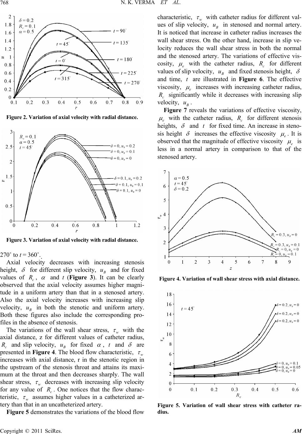 N. K. VERMA ET AL. 768 Figure 2. Variation of axial velocity with radial distance. Figure 3. Variation of axial velocity with radial distance. 270˚ to t = 360˚.. Axial velocity decreases with increasing stenosis height, for different slip velocity, u and for fixed values of c, R and t (Figure 3). It can be clearly observed that the axial velocity assumes higher magni- tude in a uniform artery than that in a stenosed artery. Also the axial velocity increases with increasing slip velocity, u in both the stenotic and uniform artery. Both these figures also include the corresponding pro- files in the absence of stenosis. The variations of the wall shear stress, w with the axial distance, z for different values of catheter radius, c and slip velocity, R u for fixed , and t are presented in Figure 4. The blood flow characteristic, w increases with axial distance, r in the stenotic region in the upstream of the stenosis throat and attains its maxi- mum at the throat and then decreases sharply. The wall shear stress, w decreases with increasing slip velocity for any value of c. One notices that the flow charac- teristic, w R assumes higher values in a catheterized ar- tery than that in an uncatheterized artery. Figure 5 demonstrates the variations of the blood flow characteristic, w with catheter radius for different val- ues of slip velocity, u in stenosed and normal artery. It is noticed that increase in catheter radius increases the wall shear stress. On the other hand, increase in slip ve- locity reduces the wall shear stress in both the normal and the stenosed artery. The variations of effective vis- cosity, e with the catheter radius, c for different values of slip velocity, R u and fixed stenosis height, and time, are illustrated in Figure 6. The effective viscosity, e t increases with increasing catheter radius, c significantly while it decreases with increasing slip velocity, R u. Figure 7 reveals the variations of effective viscosity, e with the catheter radius, c for different stenosis heights, R and t for fixed time. An increase in steno- sis height increases the effective viscosity e . It is observed that the magnitude of effective viscosity e is less in a normal artery in comparison to that of the stenosed artery. Figure 4. Variation of wall shear stress with axial distance. Figure 5. Variation of wall shear stress with catheter ra- dius. Copyright © 2011 SciRes. AM 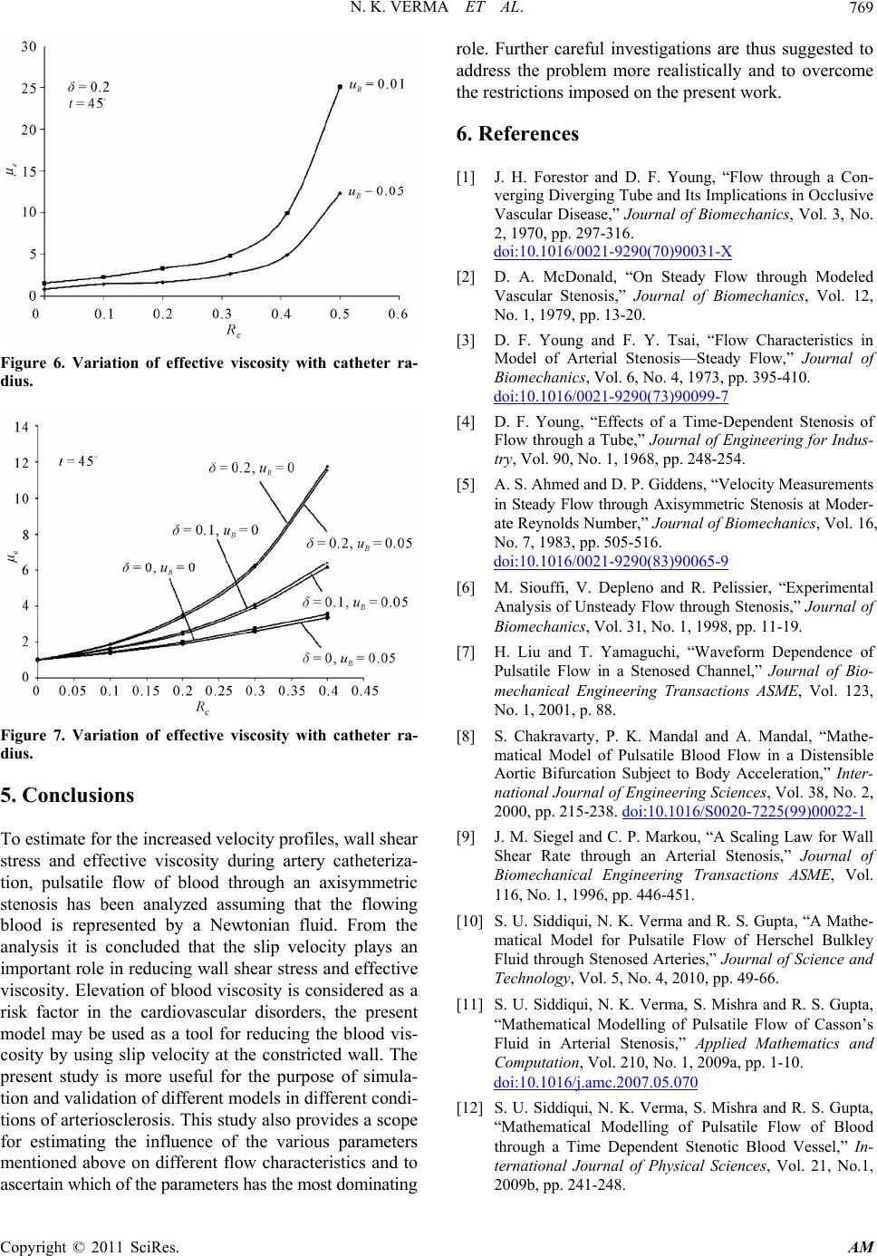 N. K. VERMA ET AL.769 Figure 6. Variation of effective viscosity with catheter ra- dius. Figure 7. Variation of effective viscosity with catheter ra- dius. 5. Conclusions To estimate for the increased velocity profiles, wall shear stress and effective viscosity during artery catheteriza- tion, pulsatile flow of blood through an axisymmetric stenosis has been analyzed assuming that the flowing blood is represented by a Newtonian fluid. From the analysis it is concluded that the slip velocity plays an important role in reducing wall shear stress and effective viscosity. Elevation of blood viscosity is considered as a risk factor in the cardiovascular disorders, the present model may be used as a tool for reducing the blood vis- cosity by using slip velocity at the constricted wall. The present study is more useful for the purpose of simula- tion and validation of different models in different condi- tions of arteriosclerosis. This study also provides a scope for estimating the influence of the various parameters mentioned above on different flow characteristics and to ascertain which of the parameters has the most dominating role. Further careful investigations are thus suggested to address the problem more realistically and to overcome the restrictions imposed on the present work. 6. References [1] J. H. Forestor and D. F. Young, “Flow through a Con- verging Diverging Tube and Its Implications in Occlusive Vascular Disease,” Journal of Biomechanics, Vol. 3, No. 2, 1970, pp. 297-316. doi:10.1016/0021-9290(70)90031-X [2] D. A. McDonald, “On Steady Flow through Modeled Vascular Stenosis,” Journal of Biomechanics, Vol. 12, No. 1, 1979, pp. 13-20. [3] D. F. Young and F. Y. Tsai, “Flow Characteristics in Model of Arterial Stenosis—Steady Flow,” Journal of Biomechanics, Vol. 6, No. 4, 1973, pp. 395-410. doi:10.1016/0021-9290(73)90099-7 [4] D. F. Young, “Effects of a Time-Dependent Stenosis of Flow through a Tube,” Journal of Engineering for Indus- try, Vol. 90, No. 1, 1968, pp. 248-254. [5] A. S. Ahmed and D. P. Giddens, “Velocity Measurements in Steady Flow through Axisymmetric Stenosis at Moder- ate Reynolds Number,” Journal of Biomechanics, Vol. 16, No. 7, 1983, pp. 505-516. doi:10.1016/0021-9290(83)90065-9 [6] M. Siouffi, V. Depleno and R. Pelissier, “Experimental Analysis of Unsteady Flow through Stenosis,” Journal of Biomechanics, Vol. 31, No. 1, 1998, pp. 11-19. [7] H. Liu and T. Yamaguchi, “Waveform Dependence of Pulsatile Flow in a Stenosed Channel,” Journal of Bio- mechanical Engineering Transactions ASME, Vol. 123, No. 1, 2001, p. 88. [8] S. Chakravarty, P. K. Mandal and A. Mandal, “Mathe- matical Model of Pulsatile Blood Flow in a Distensible Aortic Bifurcation Subject to Body Acceleration,” Inter- national Journal of Engineering Sciences, Vol. 38, No. 2, 2000, pp. 215-238. doi:10.1016/S0020-7225(99)00022-1 [9] J. M. Siegel and C. P. Markou, “A Scaling Law for Wall Shear Rate through an Arterial Stenosis,” Journal of Biomechanical Engineering Transactions ASME, Vol. 116, No. 1, 1996, pp. 446-451. [10] S. U. Siddiqui, N. K. Verma and R. S. Gupta, “A Mathe- matical Model for Pulsatile Flow of Herschel Bulkley Fluid through Stenosed Arteries,” Journal of Science and Technology, Vol. 5, No. 4, 2010, pp. 49-66. [11] S. U. Siddiqui, N. K. Verma, S. Mishra and R. S. Gupta, “Mathematical Modelling of Pulsatile Flow of Casson’s Fluid in Arterial Stenosis,” Applied Mathematics and Computation, Vol. 210, No. 1, 2009a, pp. 1-10. doi:10.1016/j.amc.2007.05.070 [12] S. U. Siddiqui, N. K. Verma, S. Mishra and R. S. Gupta, “Mathematical Modelling of Pulsatile Flow of Blood through a Time Dependent Stenotic Blood Vessel,” In- ternational Journal of Physical Sciences, Vol. 21, No.1, 2009b, pp. 241-248. Copyright © 2011 SciRes. AM  N. K. VERMA ET AL. Copyright © 2011 SciRes. AM 770 [13] I. Takuji and L. F. R. Guimaraes, “Effect of Non-New- tonian Property of Blood on Flow through a Stenosed Tube,” Fluid Dynamics Research, Vol. 22, No. 5, 1998, pp. 251-264. doi:10.1016/S0169-5983(97)00041-5 [14] R. Roos and P. S. Lykoudis, “The Fluid Mechanics of the Ureter with an Inserted Catheter,” Journal of Fluid Me- chanics, Vol. 46, No. 4, 1971, pp. 625-630. doi:10.1017/S0022112071000752 [15] D. A. McDonald, “Pulsatile Flow in a Catheterized Ar- tery,” Journal of Biomechanics, Vol. 19, No. 3, 1986, pp. 239-249. doi:10.1016/0021-9290(86)90156-9 [16] G. T. Karahalios, “Some Possible Effects of a Catheter on the Arterial Wall,” Medical Physiology, Vol. 17, No. 5, 1990, pp. 922-925. doi:10.1118/1.596448 [17] R. K. Dash, G. Jayaraman and K. N. Mehta, “Estimation of Increased Flow Resistance in a Narrow Catheterized Artery—A Theoretical Model,” Journal of Biomechanics, Vol. 29, No. 7, 1996, pp. 917-930. doi:10.1016/0021-9290(95)00153-0
|