Paper Menu >>
Journal Menu >>
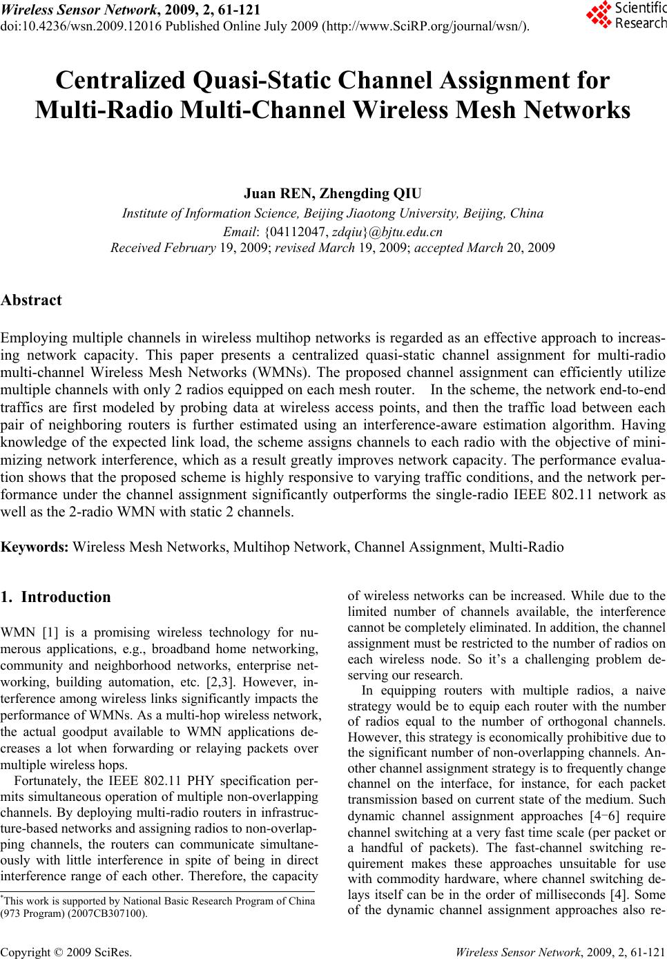 Wireless Sensor Network, 2009, 2, 61-121 doi:10.4236/wsn.2009.12016 lished Online July 2009 (http://www.SciRP.org/journal/wsn/). Copyright © 2009 SciRes. Wireless Sensor Network, 2009, 2, 61-121 Pub Centralized Quasi-Static Channel Assignment for Multi-Radio Multi-Channel Wireless Mesh Networks Juan REN, Zhengding QIU Institute of Information Science, Beijing Jiaoton g Un iversity, Beijing , China Email: {04112047, zdqiu}@bjtu.edu.cn Received February 19, 2009; rev i se d March 19, 2009; accepted March 20, 2009 Abstract Employing multiple channels in wireless multihop networks is regarded as an effective approach to increas- ing network capacity. This paper presents a centralized quasi-static channel assignment for multi-radio multi-channel Wireless Mesh Networks (WMNs). The proposed channel assignment can efficiently utilize multiple channels with only 2 radios equipped on each mesh router. In the scheme, the network end-to-end traffics are first modeled by probing data at wireless access points, and then the traffic load between each pair of neighboring routers is further estimated using an interference-aware estimation algorithm. Having knowledge of the expected link load, the scheme assigns channels to each radio with the objective of mini- mizing network interference, which as a result greatly improves network capacity. The performance evalua- tion shows that the proposed scheme is highly responsive to varying traffic conditions, and the network per- formance under the channel assignment significantly outperforms the single-radio IEEE 802.11 network as well as the 2-radio WMN with static 2 channels. Keywords: Wireless Mesh Networks, Multihop Network, Channel Assignment, Multi-Radio 1. Introduction WMN [1] is a promising wireless technology for nu- merous applications, e.g., broadband home networking, community and neighborhood networks, enterprise net- working, building automation, etc. [2,3]. However, in- terference among wireless links significantly impacts the performance of WMNs. As a multi-hop wireless network, the actual goodput available to WMN applications de- creases a lot when forwarding or relaying packets over multiple wireless hops. Fortunately, the IEEE 802.11 PHY specification per- mits simultaneous operation of multiple non-overlapping channels. By deploying multi-radio routers in infrastruc- ture-based networks and assigning radios to non-overlap- ping channels, the routers can communicate simultane- ously with little interference in spite of being in direct interference range of each other. Therefore, the capacity of wireless networks can be increased. While due to the limited number of channels available, the interference cannot be completely eliminated. In addition, the channel assignment must be restricted to the number of radios on each wireless node. So it’s a challenging problem de- serving our research. In equipping routers with multiple radios, a naive strategy would be to equip each router with the number of radios equal to the number of orthogonal channels. However, this strategy is economically prohibitive due to the significant number of non-overlapping channels. An- other channel assignment strategy is to frequently change channel on the interface, for instance, for each packet transmission based on current state of the medium. Such dynamic channel assignment approaches [4-6] require channel switching at a very fast time scale (per packet or a handful of packets). The fast-channel switching re- quirement makes these approaches unsuitable for use with commodity hardware, where channel switching de- lays itself can be in the order of milliseconds [4]. Some of the dynamic channel assignment approaches also re- *This work is supported by National Basic Research Program of China ( 973 Pro g ram ) ( 2007CB307100 ) .  J. REN ET AL. 105 Copyright © 2009 SciRes. Wireless Sensor Network, 2009, 2, 61-121 quire specialized MAC protocols or extensions of 802.11 MAC layer, making them further unsuitable for use in commodity 802.11 hardware. In order to use multiple channels with commodity hardware, several researches [7-9] focused on develop- ing techniques that assign channels statically. Such static assignments can be changed whenever there are signifi- cant changes to traffic load or network topology. Since WMN is an infrastructured network and aims to provide reliable broadband services, such changes are infrequent enough that the channel-switching delay and traffic measurement overheads are insignificant. We refer to the above as quasi-static channel assignments. However, most of the existing quasi-static channel assignments are performed offline and bound with routing. In this paper, we address the problem of quasi-static channel assignment independent of routing. A central- ized quasi-static channel assignment algorithm is pro- posed in the context of networks with multi-radio nodes. In the channel assignment, we use a novel scheme to estimate the traffic load on each wireless link. The esti- mation considers the traffic on the link itself as well as the interfering traffics introduced by its neighbors. Hav- ing knowledge of the expected load on each link, the algorithm can intelligently select different channels for each radio with the objective of minimizing network interference, which as a result efficiently improves the network capacity. To evaluate the algorithm performance, a corresponding channel assignment protocol is imple- mented in ns-2 simulations [10] and we incorporate the well-known WCETT (Weighted Cumulative Expected Transmission Time) path metric [11], which is tailored for multi-radio multihop wireless networks, into the AODV (Ad Hoc On Demand Distance Vector) routing protocol [12] as our multi-radio routing protocol. The performance evaluation shows that the proposed scheme is highly responsive to varying traffic conditions, and the network performance under the channel assignment sig- nificantly outperforms the single-radio IEEE 802.11 network as well as the 2-radio WMN with static 2 chan- nels. The rest of the paper is organized as follows. Section 2 gives the system architecture of the proposed multi-radio WMN. In Section 3, we describe the centralized quasi-static channel assignment scheme. In Section 4, we evaluate the performance of our channel assignment al- gorithm using the ns-2 simulations. Section 5 concludes the paper. 2. System Architecture In this section, we formulate the interference problem involved in wireless multihop networks and present the architecture of multi-radio multi-channel WMNs to re- solve this problem. 2.1. Interference Problem Traditional 802.11-based wireless networks can’t trans- mit data simultaneously as wired networks because of the intra-path and inter-path interference. For example in Figure 1, although the two flows transmit separately on path 1 and path 2, nodes must compete with each other for a common channel, which reduces network through- put hardly. If node 3 is in transmission, all the nodes in interference range of node 3 should keep silence, or a collision will occur. In contrast, if we assign interfering hops to different channels, then one collision domain can be broken into several collision domains with each oper- ating in a different frequency range. When the in- gress-egress node pairs that originally pass through the collision domain now take different paths to route their traffic, hops using different channels can transmit simul- taneously and the network throughput will increase. 2.2. Multi-Radio Multi-Channel WMN Architecture Figure 2 gives the architecture of multi-radio multi-chan- nel WMN. The wireless mesh backbone network consists of mesh routers (MR), mesh access routers (MAR) and the gateway. Mesh routers provide purely wireless rout- ing services. Mesh access routers provide not only wire- less routing services but also wireless access services. Each WMN has at least one gateway, which can also be served as the access point for wireless users. The integra- tion of WMN with other networks such as the Internet, cellular, IEEE 802.11, IEEE 802.15, IEEE 802.16, sen- sor networks, etc., can be accomplished through the gateway and bridging functions in the mesh routers. In WMN only end users may frequently move and mesh backbone facilities are almost static once been set- tled. In addition, both the gateway and the mesh access routers have aggregation capability. So we use them to measure the ingress-egress network traffic in our load estimation algorithm. Although in our network each router is equipped with only 2 radios, the overall network can utilize more channels with intelligent channel as- signment to every link. This is the fundamental reason for non-linear improvement in throughput with respect to the increase in number of radios per node. 10 3 4 1 7 2 8 9 6 5 Path 1 Path 2 Sender Interfere nce Range Figure 1. Interference in wireless communication.  J. REN ET AL. 106 Copyright © 2009 SciRes. Wireless Sensor Network, 2009, 2, 61-121 MAR MAR MR MAR MAR MAR MAR MR MR Internet Gateway 1 1 2 3 3 4 4 1 5 2 1 4 3 5 Virtual Link Operating on Channel 1 Figure 2. Architecture of multi-radio multi-channel WMN. 3. Design of Channel Assignment The goal of channel assignment in multi-radio WMNs is to bind each radio to a channel in such a way that the available bandwidth on each link is proportional to its expected load. The link here means direct communica- tion on a channel between the routing pair. In this section, we describe the load estimation and channel assignment algorithms. 3.1. Traffic Measurement Optimizations of channel assignment using load estima- tion require knowledge of network traffic information, so we propose to measure the end-to-end traffics between mesh access routers. The traffic measurement procedure is described as follows: At first, each mesh access router (including the gate- way) measures its ingress-egress flows by probing data periodically (the interval is set to 10s in simulations). For convenient expression, we use the access router to indi- cate both the mesh access router and the gateway in the rest of this paper. Then each access router aggregates its ingress-egress flows and sends the information to the gateway. (The gateway is used as the computation center since it owns the most powerful capacity.) After receiving the flow information, the gateway calculates the end-to-end traffic value between every pair of access routers by further aggregate the flow informa- tion. In this way, the real time value of the end-to-end traffic between each pair of access routers is measured at each echo interval. However, since what the quasi-static algorithm needed is a long-term measured traffic, the gateway performs an exponentially weighted moving average (EWMA) of each end-to-end traffic load to get an approximate long-term traffic. That is: (,)(,) (1)(,) old TsdT sdTsd (1) where denotes the end-to-end traffic between access router pair s and d. In simulations, the smoothing factor α = 0.7. (, )Tsd 3.2. Initial Expected Load Having the knowledge of the end-to-end traffics, the gateway estimates the expected load on each wireless link and assigns channels to links in order of the ex- pected loads. The gateway is required to perform a new estimation of the expected load either when it receives the traffic information for the first time, or when the dif- ference between the new traffic and the last one is large enough. To initial the load estimation, we assume that there is a link between each pair of routers in direct communica- tion range, and each end-to-end traffic load is equally divided among all the paths with the least hops between the pair of access routers. (Note that this link won’t really exist if there is no common channel assigned to the pair of routers on this link.) If the number of all shortest paths between node s and d is, and in those paths there are paths passes link i, then the initial expected load for link i to carry is calculated as follow: (, )Psd (, ) i Psd , (, ) ()( ,) (, ) i sd Psd iT Psd sd (2) Here we only count the shortest paths because the path with less hops always have much better performance compared with longer paths in multi-hop wireless net- works if they all have enough bandwidth. 3.3. Channel Assignment Having knowledge of the expected loads on all network links, we start to assign channels to links as follows: At first, all links are sorted by their expected loads. Since links expected to carry higher traffic load should be given more bandwidth, the link with the most ex- pected load is prior to other links in choosing channels. Assume every node is equipped with q radios and node a and b is connected by link i. There are three conditions for choosing a channel to link i: 1) If both of node a and b have used less than q radios, then choose a channel with the least interference with link i. (The chosen channel should also be different from the used channels of a and b.) Meanwhile, update the channel lists of node a and b. 2) If one of the two nodes (for example a) has used q channels, then choose a channel from the channel as- signment list of node a with the least interference with link i. Meanwhile update the channel list of node b. 3) When both of node a and b have used q channels: if there exists a common channel between node a and b, then assign this channel to link i; else, choose one chan- nel from the list of node a and b respectively and merge the two channels to one. Meanwhile update the channel  J. REN ET AL. 107 Copyright © 2009 SciRes. Wireless Sensor Network, 2009, 2, 61-121 lists of all nodes which connect to node a or b using the two channels directly or indirectly. When link i has been assigned a channel, we remove it from the unassigned link list. As a result, the link with lower expected load now owns the priority to choose channel next. This continues until all network links have been visited, which is denoted as a cycle of channel as- signment. 3.4. End or Feedback After a cycle of channel assignment for all links, we need to judge whether current channel assignment satisfies all bandwidth requirements. If so, we terminate the whole procedure and output the channel assignment results, or we feedback the expected link loads under new channel assignment to find a better channel assignment. It’s easy to see that, if the available bandwidth on each link is more than the traffic load it’s expected to carry, no congestion will occur. So at first we need to estimate the capacity for each link in the network. However, in wireless networks, channels are shared by all links in the same interference range. So when estimating the usable capacity of a link, we should consider all traffic loads in its interference range. According to the channel assign- ment rules, the higher load a link is expected to carry, the more bandwidth it should get. On the other side, the higher loads its interfering links are expected to carry, the less bandwidth it could obtain. Thus, the link capac- ity should be proportional to its traffic load, and be in- versely proportional to all other interfering loads. So the capacity for a link i is given by: () *() () () jIntfi Bi Ci j (3) where B is the channel bandwidth and () I ntf i stands for the set of links in the interference range of i including itself. Then the residual capacity of link i can be obtained as below: ()() ()RC iC ii (4) We use the minimal residual capacity of all links on a path as the available bandwidth for this path. Then we consider the bandwidth requirement of an end-to-end traffic is satisfied if there exists a path with its available bandwidth more than the required traffic value. At the start of the traffic allocation, the initial of each link is set to the expected capacity , and the expected load ()RC i ()Ci ()i of each link is set to 0. When a path is chosen to carry an end-to-end traffic, all links on the path reduce their residual capacities and increase their expected loads by the allocated traffic value. Assume there are totally N end-to-end traffics with respectively the value of . We choose path P with the maximal available bandwidth among all the paths with both the least hop and enough available bandwidth for traffic , which is because the WCETT path metric used in multi-channel routing protocol pre- fers to choose high throughput paths in multiple channels. When a path is chosen for traffic , there are two con- ditions when allocating traffic to this path: n T (1...,)nN n T n T 1) If min(( )) niP TRC i , we can allocate the whole traffic to path P. So we decrease the residual capacity and add the expected load of each link i on path P by . We also decrease the total unallocated traffic by for a later comparison of each iteration. n T n T n T 2) If, we can only allocate traffic to path P. So we decrease the re- sidual capacity and add the expected load of each link i in path P by . We also decrease the total unallocated traffic value by . min(()) niP TR ( ))RC i min(( )) iP RC i Ci min ( iP min(( )) iP RC i When all the N traffics have been checked, we termi- nate the whole algorithm if the total unallocated traffic equals to 0. Or, we compare the total unallocated traffic of this cycle to the last one. If the unallocated traffic of this cycle is no less than the last one, it means no im- provement is made and we also terminate the whole process. Otherwise, we feedback the new expected link loads to the channel assignment for a better scheme. After the whole algorithm ends, the gateway broad- casts the channel assignment results. Then each mesh router adjusts its radios to the assigned channels when they receive the results. If we combine the traffic measurement, load estima- tion and channel assignment, the whole algorithm proc- ess can be depicted as in Figure 3. 4. Simulation Analysis To evaluate the performance of our channel assignment, we run simulations using ns-2. We use the IEEE 802.11 MAC protocol with RTS/CTS enabled. The AODV pro- tocol is used as the routing protocol for the single-radio IEEE 802.11 network simulations. We modify the AODV protocol using the WCETT metric, a prevailing path met- ric, as our multi-radio routing protocol. The topology of all networks in the simulations is a 25-node square grid. To simplify and generalize the simulation, we configure the center node as the gateway and all the other 24 nodes as mesh access routers. The bandwidth of each channel is 2 Mbps. The ratio between interference and communica- tion range is 2 and all nodes in multi-channel networks are equipped with 2 radios.  J. REN ET AL. 108 Copyright © 2009 SciRes. Wireless Sensor Network, 2009, 2, 61-121 Channel Assignment Traffic Measurement Load Initialization All traffics have been allocated Or no improvement exists? N o End-to-End Traffics T Link L oads Capacity Estimation Link Capaciti es C Traffic Allocation Link Loads Yes End Load Estimation Figure 3. The whole al gorithm proces s . 4.1. Static Traffic Simulation 4.1.1. 10 Flows Simulation At first, we randomly choose 10 pair of nodes from the 25 nodes and assign each pair with a different CBR UDP flow. The rate of each flow is chosen randomly between 0 and 0.8Mbps. The packet size is 1000 bytes and flows run for 100 seconds. We test our channel assignment algorithm in a 5-channel network with the 10 flows. To have a good comparison, we also run the same flows in a standard IEEE 802.11 network and a 2-radio 2-channel network. The two networks both needn't any channel assignment and the 2-channel network simulation is just the original WCETT multi-radio routing simulation. We evaluate the improvement of network performance by comparing the aggregate throughputs, the average packet delays and the average packet drop probabilities of the 3 networks. The aggregate throughputs of the 3 networks are shown in Figure 4. The standard 802.11 network throughput is quite low and the 2-channel network throughput is about twice of the standard 802.11 network. Although the im- provement is significant, we can see both the two net- work throughputs suffer sharp vibration. This is because all network nodes using common channels is quite easy to bring great interference. While in the 5-channel net- work, we can efficiently limit interference to several small areas using our channel assignment. So the net- work throughput is quite stable and the value of the throughput also increases a lot. The average packet delay of each flow is shown in Figure 5. We draw the delays of flows that haven’t re- ceived any data packet successfully in the whole simula- tion to the max value of the y axis. We can see the 1-channel network performs badly with 1 flow receiving no packet. Although all flows in the 2-channel network can transport data, the average packet delays for most flows are quite large and exceed 0.5s. The maximal av- erage packet delay of the 2-channel network is up to 1.83s. In the 5-channel network, the average packet de- lays are much smaller. The maximal delay of all flows is 1.15s and there are 7 flow delays are below 0.5s. This further proves that under our channel assignment, the mesh network can efficiently utilize 5 or even more channels with only 2 radios. 010 2030405060 70 8090100 0 0.5 1 1.5 2 Time ( s) Network Aggregat e Throughput (Mbps) A ODV wi th 1 ch annel W CE TT wit h 2 channels W CE TT wit h 5 channels Figure 4. The aggre gate ne twork throughput for 10 flows. 1 23 45678 910 0 0. 5 1 1. 5 2 2. 5 Flow Index Average Pac ket Delay (s ) AODV wi th 1 channel W CE TT wit h 2 c hannels W CE TT wit h 5 c hannels Figure 5. The average packet delay for 10 flows.  J. REN ET AL. 109 Copyright © 2009 SciRes. Wireless Sensor Network, 2009, 2, 61-121 We also compare the average packet drop probability of each flow in Figure 6. The probabilities for the previ- ous two networks are all quite large. In the 5-channel network, the probabilities of 4 flows are quite small with values below 4%. Although the ones for the other flows are large, but they have decreased a lot compared to the previous two networks. 4.1.2. 20 Flows Simulation To derive the network to saturation, we randomly choose 20 pair of nodes from the 25 nodes and run the same simulations in the above 3 networks. The aggregate thro- ughput of the 3 networks is shown in Figure 7. From Figure 7 we can see the throughput gain for 2-channel network is not significant under the heavy traffic. While both the value and the stability of throughput for 5-channel network get further significant increase, which is due to the sufficient bandwidth brought by efficient utilization of multiple channels. The average packet delay of each flow is shown in Figure 8. We can see that in the 1-channel network, 4 flows received no packet in the whole simulation. In the 2-channel network, the average packet delays for most flows are also quite large with the maximal average de- lay up to 2.32s for the 19th flow. While in the 5-channel network, the average packet delays for most flows are below 0.5s and the maximal one is only 0.96s. We compare the average packet drop probability of each flow in Figure 9. The average packet drop prob- abilities for all the three networks are all quite large be- cause of the heavy traffic. While compared to the two networks without channel assignment, the average packet drop probability for the 5-channel network is still much smaller and the average drop probability of 9th flow is nearly 0, which means it has almost transmitted all the data packets successfully. 1 23 45 67 8910 0 20 40 60 80 100 Fl ow Index Average Pac ket Drop Probability (%) A ODV wi t h 1 c h annel WCETT wit h 2 channels WCETT wit h 5 channels Figure 6. The average packet drop probability for 10 flows. 010 2030405060 708090 100 0 0.5 1 1.5 2 2.5 3 Time ( s) Network A ggregat e Throughput (Mbps) A ODV with 1 channel WCETT wit h 2 channel s WCETT wit h 5 channel s Figure 7. The aggre gate ne twork throughput for 20 flows. 12345678910 11 1213 14 15161718 19 20 0 0.5 1 1.5 2 2.5 Fl ow Index A v e rage P a cket Del ay (s) A ODV wit h 1 channel WCE TT wi t h 2 channels WCE TT wi t h 5 channels Figure 8. The average packet delay for 20 flows. 12345678910 11 1213 14 1516 17 1819 20 0 20 40 60 80 100 Fl ow Index Average Pack et Drop Probability (%) AO DV with 1 channel W CE TT wit h 2 channel s W CE TT wit h 5 channel s Figure 9. The average packet drop probability for 20 flows.  J. REN ET AL. 110 Copyright © 2009 SciRes. Wireless Sensor Network, 2009, 2, 61-121 Table 1. Comparison of the average aggregate throughput. AODV WCETT WCETT + Channel Assignment Average Aggregate Througput (Mbps) 1 channels 2 channels 3 chan- nels 4 chan- nels 5 chan- nels 10 flows 0.525 0.903 1.231 1.4371.608 20 flows 0.777 0.814 1.448 2.0802.323 020 40 60 80100 120140 160 180 0 0. 5 1 1. 5 2 2. 5 Ti me ( s) Net work Aggregat e T hrough put (M bps) Figure 10. Impact of traffic change on aggregate network throughput. 4.1.3. The Average Aggregate Throughput Comparison Without loss of generality, we also run the 10 and 20 flows respectively in the networks with 3 and 4 channels, using the proposed channel assignment. We list the av- erage aggregate throughputs of the 5 networks with 2 different traffics in Table 1. We see that the network throughput increases with more channels assigned to the network. While the improvement can’t be achieved as high times as the number of channels, due to the unne- glectable management packets and probing packets for both the WCETT path metric and traffic measurement. 4.2. Varying Traffic Simulation To evaluate the impact of traffic change on network per- formance, we randomly choose 3 flows in the 10-flow scene and vary their sending rates in the simulation. Flows run for 180 seconds. At the 60th second, we in- crease the sending rate of a flow by 0.2Mbps. Then at the 80th second, we increase the sending rate of another flow by 0.4Mbps. At the 100th second, we decrease the send- ing rate of the third flow by 0.4Mbps. After this, the traf- fic changes are large enough for the gateway to reassign channels. Because the traffic measurement interval is 10 seconds, the gateway should detect the traffic change and start to reassign channels at the 110th second. Besides, each node need to fresh its routing table since the net- work channel assignment has changed. So we purge the history information of the WCETT path metric in each node after every new channel assignment. Figure 10 shows the serial changes of aggregate net- work throughput by varying the flow sending rates. We can see from the 60th second to the 110th second, the ag- gregate network throughput changes slightly after each variation of flow sending rate and at last stays around 1.85Mbps. Then at the 110th second, the aggregate throughput suddenly decreases to 0, which means the network begins to reassign channels. After about 15 seconds vibration, the aggregate throughput comes back to near 2.4Mbps which means the new channel assign- ment as well as the WCETT path metric routing have terminated. Compared to the last 1.85Mbps throughput before channel reassignment, the network now owns a much better bandwidth assignment. In addition, the channel reassignment and routing together cost only about 15 seconds. So we can say our channel assignment combin- ing with the WCETT path metric routing provides a good choice for the multi-radio WMNs. 5. Conclusions This paper formulated the channel assignment problem in multi-radio multi-channel WMNs. Since the backbone of WMN is an infrastructured network, we assume the mesh routers are stationary and each of them is equipped with 2 radios. Based on network traffic measurement and the load estimation of wireless links, we present a cen- tralized quasi-static channel assignment with the objec- tive of minimizing network interference, which as a re- sult greatly improves network capacity. Extensive simu- lations show that the proposed scheme is highly respon- sive to varying traffic conditions, and the network per- formance under the channel assignment significantly outperforms the single-radio IEEE 802.11 network as well as the 2-radio WMN with static 2 channels. 6. References [1] Mesh Networks Inc. http://www.meshnetworks.com. [2] I. F. Akyildiz, X. D. Wang, and W. L. Wang, “Wireless mesh networks: A survey,” Computer Networks, Vol. 47, No. 4, pp. 445–487, 2005. [3] Mesh Networking Forum, “Building the business case for implementation of wireless mesh networks,” Mesh Net- working Forum 2004, San Francisco, CA, October 2004.  J. REN ET AL. 111 Copyright © 2009 SciRes. Wireless Sensor Network, 2009, 2, 61-121 [4] R. Chandra and P. Bahl, “MultiNet: Connecting to multi- ple IEEE 802.11 networks using a single wireless card,” INFOCOM, Vol. 2, pp. 882–893, 2004. [5] I. Wormsbecker and C. Williamson, “On channel selec- tion strategies for multi-channel MAC protocols in wire- less ad hoc networks,” IEEE Conference on Wireless and Mobile Computing, Networking and Communications (WiMob’2006), pp. 212–220, 2006. [6] J. So and N. Vaidya, “Multi-channel MAC for ad hoc networks: Handling multi-channel hidden terminals using a single transceiver,” MobiHoc’04, May 24–26, 2004. [7] A. Raniwala, K. Gopalan, and T. Chiueh, “Centralized channel assignment and routing algorithms for multi- channel wireless mesh networks,” ACM Mobile Com- puting and Communications Review, Vol. 8, No. 2, pp. 50–65, 2004. [8] J. Tang, G. Xue, and W. Zhang, “Interference-aware to- pology control and QoS routing in multi-channel wireless mesh networks,” ACM SIGMOBILE, Urbana-Champaign, IL, pp. 68–77, 2005. [9] A. Subramanian, H. Gupta, and S. R. Das, “Mini- mum-interference channel assignment in multi-radio wire- less mesh networks,” Proceedings of 4th Annual IEEE Communications Society Conference on Sensor, Mesh and Ad Hoc Communications and Networks ( SECON’'07), pp. 481–490, June 18–21, 2007. [10] “ns-2 simulator,” http://www.isi.edu/nsnam/ns. [11] R. Draves, J. Padhye, and B. Zill, “Routing in multi-radio, multi-hop wireless mesh networks,” in Proceedings of ACM MOBICOM, pp. 114–128, September 2004. [12] C. Perkins, E. Royer, and S. Das, “Ad hoc on demand distance vector (AODV) routing,” IETF Internet Draft, draft-ietf-manet-aodv2-10.txt, January 24, 2002. |