 Journal of Applied Mathematics and Physics, 2014, 2, 1105-1112 Published Online November 2014 in SciRes. http://www.scirp.org/journal/jamp http://dx.doi.org/10.4236/jamp.2014.212128 How to cite this paper: Bahrim, C., Raju, M.M., Khairuzzaman, M., Hsu, W.-T., Lanning, R.N. and Duplan, D. (2014) A New Optoelectronic Switch: The Dielectric of a Capacitor Illuminated with a Laser Radiation. Journal of Applied Mathematics and Physics, 2, 1105-1112. http://dx.doi.org/10.4236/jamp.2014.212128 A New Optoelectronic Switch: The Dielectric of a Capacitor Illuminated with a Laser Radiation Cristian Bahrim*, Md Mozammal Raju, Md Khairuzzaman, Wei-Tai Hsu, Robert Nick Lanning, Don Duplan Department of Physics, La mar University, Beaumont, Texas, USA Email: *cristian.bahrim@la mar.edu Received August 2014 Abstract A dielectric changes its optical and electric characteristics when an external source provides enough energy. We analyze the interaction between a laser beam and a dielectric surface placed between two metal plates in a capacitor-type configuration. We show that a voltage applied across the dielectric can shift the wavelength of the laser radiation as perceived by its electric dipoles. The optical behavior of the dielectric in this arrangement recommends the device as a possible optoelectronic switch which can be driven by a relatively small capacitor voltage. Keywords Optoelectronic Devi ce, Las er-M atter Interact ion, Relative Perm i ttiv ity , Polarization of Light 1. Introduction A dielectric material is a collection of dipole molecules where the electronic charge forms an ellipsoid of rota- tion and has two poles: a positive pole near the nuclei and a negative pole where there is a larger concentration of electronic charge. When the dielectric is illuminated with radiation of low intensity, the electronic cloud has a linear response and oscillates harmonically with respect to the equilibrium position, at the same frequency as the incident radiation, or absorbs the radiation resonantly becoming opaque. In our experiment we will use dense flint glass, which is a heavy silica-based glass doped with PbO molecules, irradiated with 532 nm from a diode laser. In our experiment the dielectric is transparent to the radiation used because a laser beam of 532 nm has much lower photon energy than what is needed for reaching the first excited state. Our flint glass becomes opa- que in UV at 132.44 nm [1]. The choice of using radiation of 532 nm is because the green light can be easily observed by a normal human eye even when the light is dimmer, as it is the case in our measurements of Brew- ster angle. We use a diode laser because it is more stable over a longer period of time as compared with other lasers. The electric dipoles of the dielectric illuminated with 532 nm oscillate with a frequency of about 5.6 × 10¹⁴ * 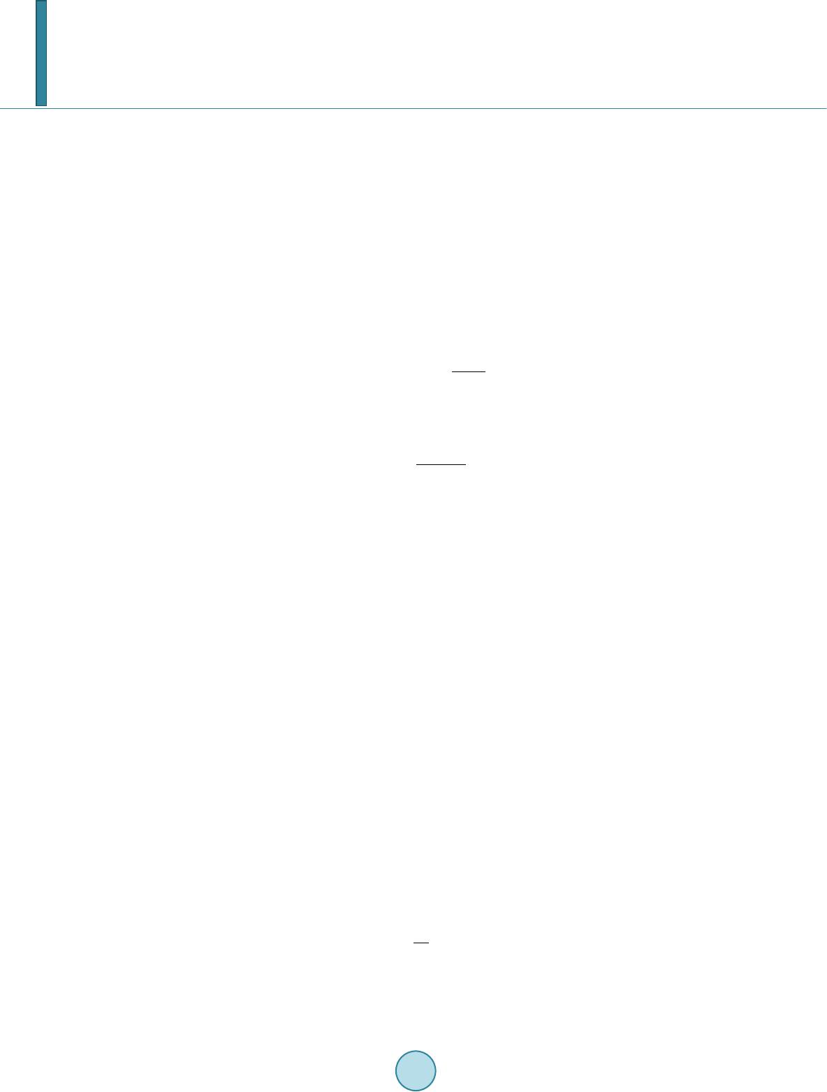 C. Bahrim et al. Hz and induce an electric field which propagates forward, in transmission. Each electric dipole oscillates as a small antenna and passes the information about the incident light to the next dipole. The amplitude of oscillation for all dipoles is the same for a dielectric with a linear response. However, each subsequent dipole in the dielec- tric has a momentarily displacement which is slightly different than the previous one and the next dipole in the direction of light propagation. The modulation of this gradual change of the dipoles’ displacement builds-up the transmitted electric field (or ET-field). Part of the radiation is also reflected back at an angle equal to the angle of incidence, according to the Fer- mat’s Principle. This radiation forms the reflected electric field (or ER-field). The resonant interaction between the electric field component of the incident radiation (or EI-field) and the electric dipoles induces a chain of di- pole moments in the dielectric material which oscillates exactly in-phase with the incident field. A dipole moment is the product of the electronic charge of one pole and its displacement [2]. The electric dipoles build together the net electric polarization of the dielectric, P which oscillates in-phase with the EI-field. The ratio of these two fields defines the electric permittivity, ε , of the dielectric: (1) where the absolute permittivity ε 0 is 0.00885 pF/mm. The relative permittivity ε r of the dielectric indicates the degree of polarization of the material’s dipoles with respect to vacuum: (2) The relative permittivity allows one to define the index of refraction of the dielectric as (3) This index of refraction represents a measure of the optical response of the material and indicates by how much a radiation slows down when passing through it. Reflection of light is a kind of back scattering at the dielectric surface that occurs whenever light experiences a discontinuity in the incident medium. The plane of incidence is defined by the incident, reflected, and trans- mitted rays, as shown in Figure 1. It is possible to polarize the reflected light at the interaction with a dielectric surface. This happens at a precise angle of incidence called “Brewster angle”, θ B. When light is incident at θ B there is no reflected component in the plane of incidence and all the light reflected is polarized in the plane per- pendicular to the plane of incidence. Hence, the parallel component of the reflectance vanishes. The reflectance is defined as the irradiance associated to the reflected light of the ER-field [2]. This phenomenon can simply and elegantly be explained by using the electric dipole oscillator model pro- posed by Lorentz [2]. Figure 1 shows an incident EI-field of amplitude E0I polarized parallel to the plane of in- cidence. For an arbitrary angle of incidence, θ I, the reflected ER-field of amplitude E0R and the transmitted ET- field of amplitude E0T are also polarized in the same plane. Both directions of reflected and transmitted rays are decided by the fact that light travels the path of least time (according to the Fermat’s Principle). Also, it is well-known that an electric dipole cannot radiate energy along its axis of oscillation, but perpendicular on it. When the direction of reflected light happens to be perpendicular on the direction of transmitted light, which is for incidence at angle θ B, then only the parallel component within the plane of incidence of the reflected light vanishes. Using simple geometric reasoning one can find that (4) and using the Snell’s law we find the Brewster’s law [2] (5) In our data analysis we use a value of the refractive index for air (which is the incident medium), nI of 1.00 029. 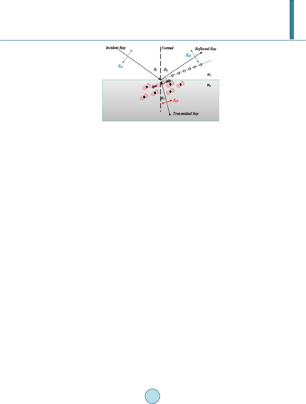 C. Bahrim et al. Figure 1. The plane of incidence. The electric dipoles oscillate perpen dicular on the transmitted ray. For incidence at Brewster angle, only the perpendicular component on the plane of inci- dence of the ER-field is reflected (open circles along the dotted line), while the parallel component vanishes. The purpose of our experiment is to use one laser source for modifying the Brewster angle and implicitly the index of refraction of the dielectric according to Equation (5). This changes also the relative permittivity ac- cording to Equation (3). The reason for such a variation of the optoelectronic characteristics is because the di- electric’s dipoles perceive a shifted value of the wavelength of the incident radiation due to the presence of an external source of energy which covers uniformly the dielectric surface. In Section 2 we will describe the experimental setup and our experimental technique adopted for finding pre- cise values of the Brewster angle from measurements of irradiances reflected (called hereafter “reflectances”) in a region of a few degrees wide near the Brewster angle (called hereafter “Brewster region”). In Section 3 we will present the theoretical interpretation, while the Conclusion will follow in Section 4. 2. The Experimental Method 2.1. Experimental Setup Using the setup from Figure 2 we can observe the variation of the refractive index of the dielectric, nd, with the change in the voltage applied across the capacitor that includes the dielectric. The capacitor has two parallel aluminum plates placed on the top and bottom of the dielectric material. Several voltages have been applied in order to produce different shifts of the laser’s wavelength as perceived by the dielectric, and implicitly a change in the Brewster angle value and the relative permittivity of the dielectric. We use a green diode laser of wavelength 532 nm incident on a dense flint glass. The laser radiation passes through a beam splitter which splits the light into two parts: One part is sent to a monitoring branch for moni- toring the stability of the probe laser and another part is sent through collimating slits incident on the dielectric surface. The light reflected by the dielectric is further detected along the detector branch using a high sensitivity light sensor. The incident light is attenuated to the desired intensity and next, polarized at 45˚ with respect to the plane of incidence so that it has equal intensities in the parallel and perpendicular components defined with re- spect to the plane of incidence (shown in Figure 1). The light signal is carefully collimated before is incident on the dielectric surface and has the same diameter where it impinges the surface throughout the experiment. Thus, on the dielectric surface the interaction between the electric dipoles and the parallel and perpendicular components of the incident light is done evenly. Using a linear polarizer on the detector branch we can separate the two components of the reflected light by the dielec- tric surface. We observe that the parallel and perpendicular reflectances have different values [1]. Finally, the light detected by a high sensitivity photocell is transmitted to a computer interface for data processing, along with the value of the angular position of the incident beam. In order to find the Brewster angle, we need to scan a wider angular interval, of about 15˚, near the region where the parallel component of the reflectance vanis he s.  C. Bahrim et al. Figure 2. Th e experimental setup. The capacitor includes a dielectric placed between two parallel metal plates. 2.2. Observables in Our Experiment In our experiments, finding the Brewster angle requires to measure the parallel (R║) and perpendicular (R⊥) components of the reflectance with respect to the plane of incidence. The analytic form for these two reflec- tances can be derived using the Maxwell’s equations for electromagnetic waves incident on surfaces. The inte- raction at surface imposes boundary conditions and generates the Fresnel’s equations (for details see [2]): ( ) ( ) 2 || tan , tan IT IT R θθ θθ − = + (6) ( ) ( ) 2 sin . sin IT IT R θθ θθ ⊥ − = + (7) The major disadvantage of using these two components is that they do not have a simple variation near the Brewster angle. Furthermore, the variation of the parallel component is very shallow near θ B and makes the pre- cision in finding its value to be very poor (It is about 0.1˚ in standard measurements with similar equipment [3]). Bahrim and Hsu discovered in [1] that a normalization of the parallel (R║) and perpendicular (R⊥) components to the total component generate two equations that can be fitted with a simple parabolic function in a region about 15˚ wide near θ B angle: ( ) () () 2 s || || 22 co , cos cos IT IT IT R RR θθ θθ θθ + = =++ − (8) ( ) () () 2 22 cos , cos cos IT IT IT R RR θθ θθ θθ ⊥ ⊥ − = =++ − (9) which leads to a theoretical minimum value of 0 for R║ (at θ B) and a maximum value of 1 for R⊥ (at θ B). Howev- er, experimentally does not exactly vanish at θ B angle but it reaches a very small value that can be still resolved with our detection system. This experimental choice is for practical reasons because we cannot know a priori the exact value of the Brewster angle. First we need to perform the best parabolic fit using all the experimental data points located both at lower and higher angular values than θ B before we can find an accurate value for θ B. Therefore our minimum value for R║ at θ B has only a relative zero value.  C. Bahrim et al. For stability purposes, throughout the experiment we have collected raw data for at least 15 seconds following the conclusions previously published by Hsu and Bahrim in [4]. Figure 3 shows a test case for the variation of the angular value with the stability of the reflectance detected. Our studies indicated that we need to wait for about 9 seconds before the signal detected reaches a plateau of stability. Hence we have to process data collected only between 10 to 15 seconds. Our technique allows finding Brewster angles with a precision of 0.001˚ which is 100 times better [4] than measurements using similar equipment [3]. 3. Data Analysis Varying the capacitor voltage from 0 V to 9 V, we were able to observe small changes of refractive indices, due to the variation of the Brewster angle, with a similar precision as in other previous experiments where we have used an isotropic energy source, such as a blackbody radiation [5]. The present experimental method allows us to generate accurate dispersive curves having a precision similar with other more sophisticated experimental techniques, such as “the minimum deviation method” reported in [6]. 3.1. Theoretical Model In our present experiment, the dielectric is part of a capacitor configuration and therefore, the uniform voltage applied across its surface supplies an extra energy U that can be simply added to the probe signal, E1, and thus, produces another energy, E2, which is the one actually perceived by the dielectric’s oscillating dipoles: (10) Equation (10) is graphically represented in Figure 4. The scalar addition of energies in Equation (10) is the consequence of the conservation of energy for our closed system formed by the dielectric surface irradiated with light of λ 1 = 532 nm and having a voltage across it. Using Planck-Einstein hypothesis regarding light as a photon E = hc/λ where hc is the product of Planck con- stant and the speed of light in vacuum, the Equation (10) becomes (11) The change in the wavelength of the reflected light as perceived by the dielectric surface leads to a shifted value of the index of refraction and the dielectric’s relative permittivity. In our experimental conditions, the la- ser’s wavelength shifts from λ 1 of 532 nm at 3.0 V (where U = 0), to λ 2 of 518 nm at 4.0 V (where U = 0.0629 eV), 495 nm at 6.0 V (where U = 0.1742 eV) and 475 nm at 9.0 V (where U = 0.2797 eV). 3.2. Results and Interpretation We illuminated the surface of a flint glass prism with radiation laser of 532 nm and varied the voltage across the capacitor (hereafter called “capacitor vol t age”) from 0 to 9 V. We generated the plot shown in Figure 5. We observe a decrease in the value of the Brewster angle with the increase of the capacitor voltage from 0 to 0.5 V, followed by a quasi-linear increase above 1 V. This quasi-linear variation is consistent with Equation (10) for the conservation of energy and also, with the ability of the dipoles to have a harmonic response to the presence of an additional energy, U, distributed uniformly on the dielectric surface. A linear trend of the Brewster angle indicates that both the laser and the capacitor voltage provide energies which are weak enough so that the dielectric dipoles oscillate harmonically. In our experimental conditions the dipoles have a linear elastic response under the action of the incident EI-field which is greatly helped by the very small electronic inertial mass. This means that the net Coulomb force due to both the EI-field and the capacitor voltage acts linearly on the dipoles closely follo wing the Hooke’s law: F = −kx, for a simple harmonic oscillator, where x is the elongation of the dielectric dipoles and k is the spring constant of the electronic cloud. From Figure 5 we observe that the result at 3V almost coincides with the value at 0V (where no voltage is applied across the capacitor). In Figure 6 it is interesting to remark that a similar variation with the capacitor voltage is obtained for the relative permittivity, after using subsequently Equations (5) and (3). This observation reinforces the above interpretation with the linear response of the electric dipoles. The uniform EC-field associated to the capacitor voltage establishes a uniform source of energy for all dipoles 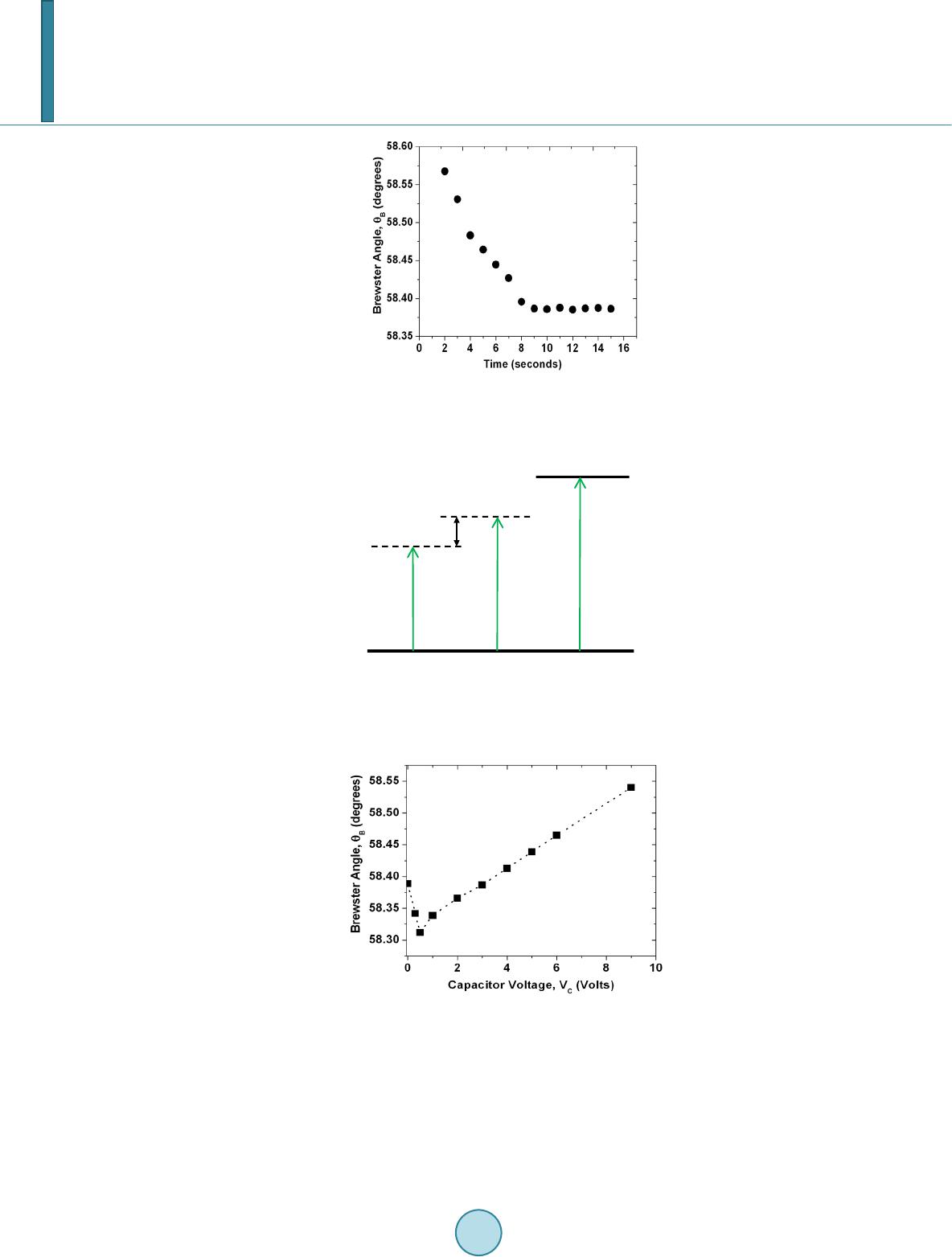 C. Bahrim et al. Figure 3. An example of the variation of Brewster angle with the time of detection at VC = 3V . A threshold of stability is reached for any voltage after about 9 - 10 seconds.. Figure 4. A schematic energy diagram associated to Equation (10). λ 0 is the opacity wavelength, which is 132.44 nm for a dense flint glass illuminated with 532 nm [1]. Figure 5. The variation of θ B with VC. on the dielectric’s surface and creates an even attraction of their poles towards the plates of opposite polarity due to the Coulomb force. Due to the capacitor voltage the dipoles become more polarized (or elongated) on the di- electric surface and the degree of polarization increases with the voltage. On the other hand the incident laser radiation is linearly polarized at 45˚ from the plane of incidence and will also tend to align the dipoles along the direction of polarization of the EI-field according to the Lorentz model described in the Introduction. When both fields are acting simultaneously on the dipoles a competition occurs that can explain the variation of the 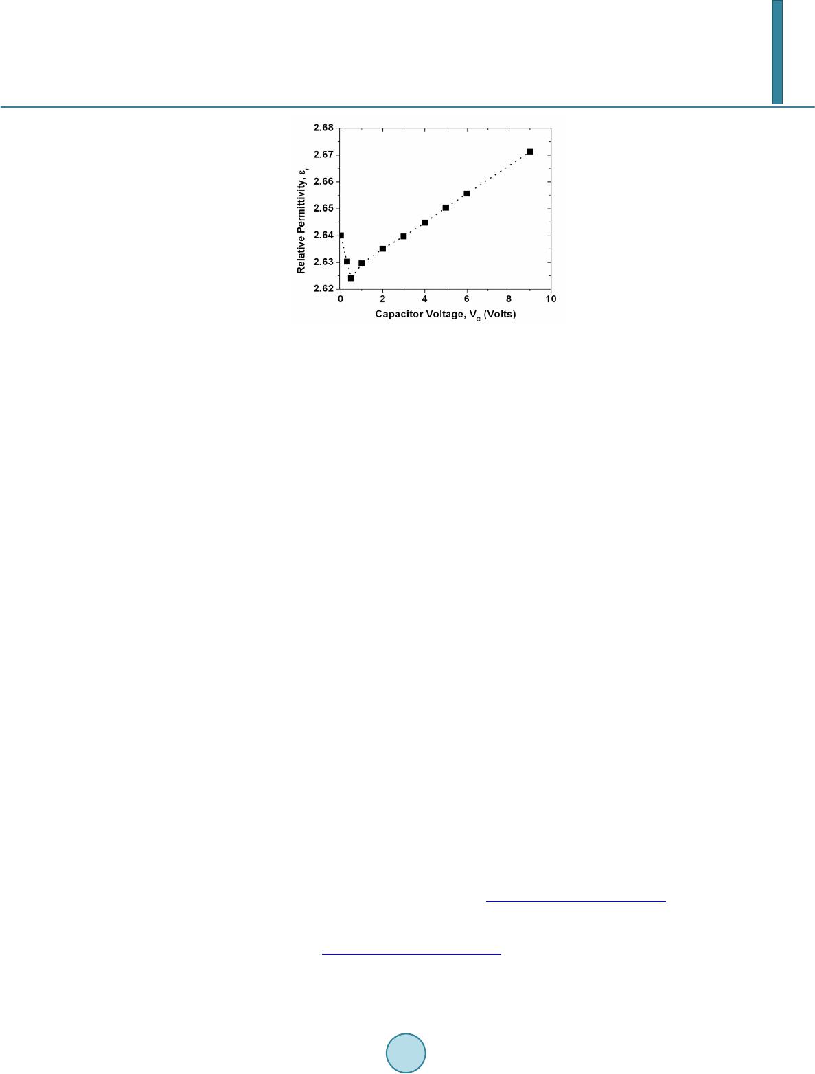 C. Bahrim et al. Figure 6 . The variation of ε R with VC. relative permittivity with the capacitor voltage reported in Figure 6. Thus, for very small capacitor voltages, lower than 0.5 V in our case, the electric dipoles on the dielectric surface align themselves along the EI-field of the laser beam which is tilted 45˚ from the plane of incidence, thus providing a polarization-like effect which reduces the net charge on the capacitor’s plates and implicitly the ca- pacitance. When the capacitor voltage slightly exceeds 0.5 V the electric field of the probe laser does not man- age to align alone the dipoles anymore and the dipoles’ orientation starts to be gradually dominated by the EC-field of the capacitor, thus working in increasing the charge on the plates for the same capacitor voltage (VC) and also the capacitance according to the relationship C = Q/VC. The competition between the two electric fields at 3V makes the flint glass illuminated with a laser beam of 532 nm and 2 mm in diameter to generate the same dielectric response as for the case without voltage across the dielectric. With a further increase of the capacitor voltage the orientation of the electric dipoles is strongly dominated by the EC-field associated to VC. Due to an additional energy, U, from the capacitor voltage, the dipoles on the dielectric will oscillate linearly at higher frequencies, as indicated by Equation (11). This is causing a lower inertial resistance, and therefore, higher rela- tive permittivity. 4. Conclusion The general trend in the variation of the relative permittivity with the change in the capacitor voltage shown in Figure 5 for the test case of a dense flint glass illuminated with a laser radiation of 532 nm is expected to be al- most the same for any type of dielectric. However, the actual voltages for the minimum value of the relative permittivity (for flint is at 0.5 V) and for the resetting to the initial conditions at no capacitor voltage (for flint is at 3 V) will certainly be different. The reason appears clear from the actual meaning of the relative permittivity, which represents a measure of the degree of polarization of the dielectric material according to Equation (2). A material with larger net atomic polarization, P, will have larger relative permittivity, ε r, as indicated by equation (2) and will most likely require a larger capacitor voltage for the alignment of the electric dipoles along the EC-field. Also the intensity of the laser field and the waist of the laser beam are two important factors that need to be considered. The region of transition in the dielectric polarization property from a polarization driven by the EI-field of the laser to the EC-field of the capacitor voltage can make this device when illuminated with laser radiation to function as an optoelectronic switch. References [1] Bahrim, C. and Hsu, W.-T. (2009) Precise Measurements of the Refractive Indices for Dielectrics Using and Improved Brewster Angle Method. American Journal of Physics, 77, 337-343. http://dx.doi.org/10.1119/1.3056583 [2] Hecht , E. (2002) Optics. 4th Edition , Addison Wesley, San Francisco. [3] Ouseph, P.J., Dri ver, K. and Conklin, J. (2001 ) Polarization of Light by Reflection and the Brewster Angle. American Journal of Physics, 69, 1166-1168. http://dx.doi.org/10.1119/1.1397457 [4] Hsu, W.-T. and Bahrim, C. (2009 ) Accurate Measurements of Refractive Indices for Dielectrics in an Undergraduate Optics Laboratory for Science and Engineering Students. European Journal of Physics, 30, 1325-1336.  C. Bahrim et al. http://dx.doi.org/10.1088/0143-0807/30/6/010 [5] Bahrim, C., Duplan, D., Hsu, W.-T. and Lanning, R. (2012) Measuring the Curve of Dispersion for Dielectrics Using a Low-Energy Laser and a Thermal Source of Radiation. Bulletin of the American Physical Society, APS March Meeting 2012, Boston, 27 February-2 March 2012, B32.00013. [6] Bahrim, C. (2006) A Modern Optics Laboratory for Undergraduate Students in Science and Engineering. In: Aung, W., Crosthwaite, C., Espinosa, R.Y., Moscinski, J., Ou, S.-H. and Ruiz, L.M.S., Ed., Innovations 2006. World Innovations in Engineering Education and Research, iNEER, Beggell House, Arlington, Chapter 17.
|