Paper Menu >>
Journal Menu >>
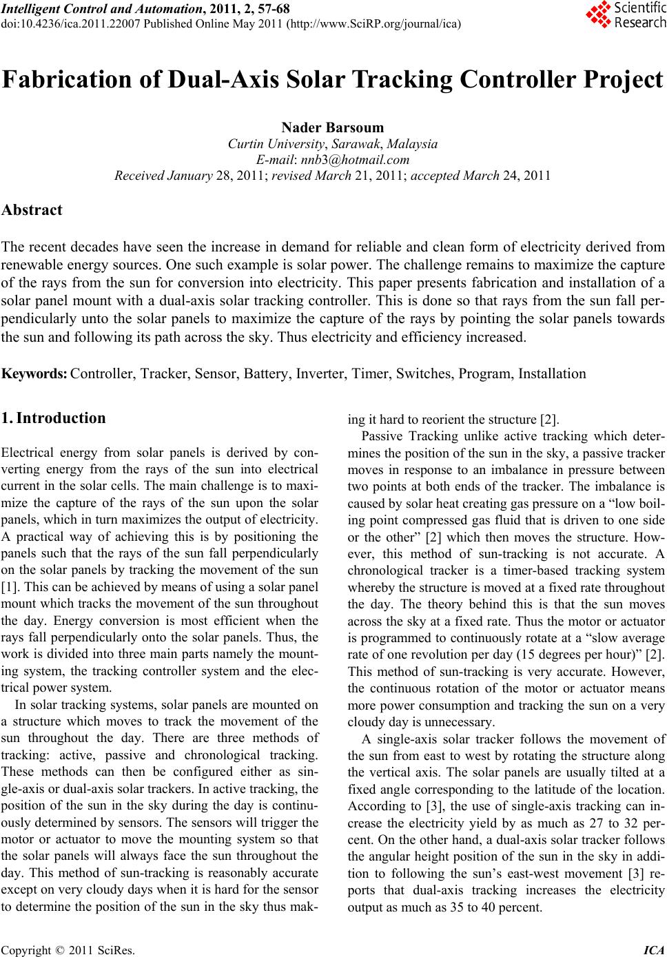 Intelligent Control and Automation, 2011, 2, 57-68 doi:10.4236/ica.2011.22007 Published Online May 2011 (http://www.SciRP.org/journal/ica) Copyright © 2011 SciRes. ICA Fabrication of Dual-Axis Solar Tracking Controller Project Nader Barsoum Curtin University, Sarawak, Malaysia E-mail: nnb3@hotmail.com Received January 28, 2011; revised March 21, 2011; acce p te d Ma rch 24, 2011 Abstract The recent decades have seen the increase in demand for reliable and clean form of electricity derived from renewable energy sources. One such example is solar power. The challenge remains to maximize the capture of the rays from the sun for conversion into electricity. This paper presents fabrication and installation of a solar panel mount with a dual-axis solar tracking controller. This is done so that rays from the sun fall per- pendicularly unto the solar panels to maximize the capture of the rays by pointing the solar panels towards the sun and following its path across the sky. Thus electricity and efficiency increased. Keywords: Controller, Tracker, Sensor, Battery, Inverter, Timer, Switches, Program, Installation 1. Introduction Electrical energy from solar panels is derived by con- verting energy from the rays of the sun into electrical current in the solar cells. The main challenge is to maxi- mize the capture of the rays of the sun upon the solar panels, which in turn maximizes the output of electricity. A practical way of achieving this is by positioning the panels such that the rays of the sun fall perpendicularly on the solar panels by tracking the movement of the sun [1]. This can be achieved by means of using a solar panel mount which tracks the movement of the sun throughout the day. Energy conversion is most efficient when the rays fall perpendicularly onto the solar panels. Thus, the work is divided into three main parts namely the mount- ing system, the tracking controller system and the elec- trical power system. In solar tracking systems, solar panels are mounted on a structure which moves to track the movement of the sun throughout the day. There are three methods of tracking: active, passive and chronological tracking. These methods can then be configured either as sin- gle-axis or dual-axis solar trackers. In active tracking, the position of the sun in the sky during the day is continu- ously determined by sensors. The sensors will trigger the motor or actuator to move the mounting system so that the solar panels will always face the sun throughout the day. This method of sun-tracking is reasonably accurate except on very cloudy days when it is hard for the sensor to determine the position of the sun in the sky thus mak- ing it hard to reorient the structure [2]. Passive Tracking unlike active tracking which deter- mines the position of the sun in the sky, a passive tracker moves in response to an imbalance in pressure between two points at both ends of the tracker. The imbalance is caused by solar heat creating gas pressure on a “low boil- ing point compressed gas fluid that is driven to one side or the other” [2] which then moves the structure. How- ever, this method of sun-tracking is not accurate. A chronological tracker is a timer-based tracking system whereby the structure is moved at a fixed rate throughout the day. The theory behind this is that the sun moves across the sky at a fixed rate. Thus the motor or actuator is programmed to continuously rotate at a “slow average rate of one revolution per day (15 degrees per hour)” [2]. This method of sun-tracking is very accurate. However, the continuous rotation of the motor or actuator means more power consumption and tracking the sun on a very cloudy day is unnecessary. A single-axis solar tracker follows the movement of the sun from east to west by rotating the structure along the vertical axis. The solar panels are usually tilted at a fixed angle corresponding to the latitude of the location. According to [3], the use of single-axis tracking can in- crease the electricity yield by as much as 27 to 32 per- cent. On the other hand, a dual-axis solar tracker follows the angular height position of the sun in the sky in addi- tion to following the sun’s east-west movement [3] re- ports that dual-axis tracking increases the electricity output as much as 35 to 40 percent. 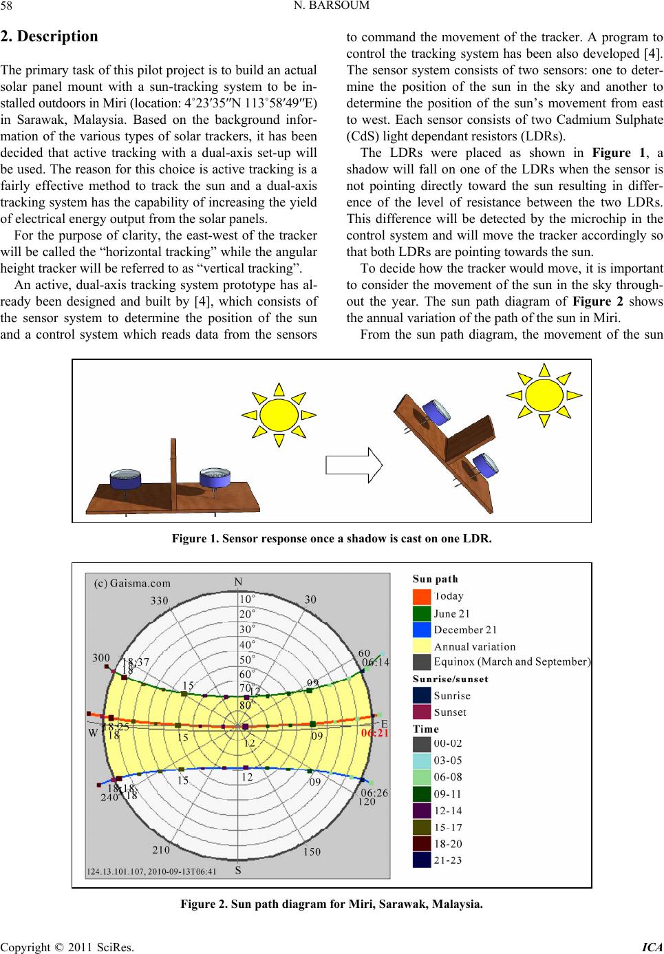 N. BARSOUM 58 2. Description The primary task of this pilot project is to build an actual solar panel mount with a sun-tracking system to be in- stalled outdoors in Miri (location: 4˚23′35″N 113˚58′49″E) in Sarawak, Malaysia. Based on the background infor- mation of the various types of solar trackers, it has been decided that active tracking with a dual-axis set-up will be used. The reason for this choice is active tracking is a fairly effective method to track the sun and a dual-axis tracking system has the capability of increasing the yield of electrical energy output from the solar panels. For the purpose of clarity, the east-west of the tracker will be called the “horizontal tracking” while the angular height tracker will be referred to as “vertical tracking”. An active, dual-axis tracking system prototype has al- ready been designed and built by [4], which consists of the sensor system to determine the position of the sun and a control system which reads data from the sensors to command the movement of the tracker. A program to control the tracking system has been also developed [4]. The sensor system consists of two sensors: one to deter- mine the position of the sun in the sky and another to determine the position of the sun’s movement from east to west. Each sensor consists of two Cadmium Sulphate (CdS) light dependant resistors (LDRs). The LDRs were placed as shown in Figure 1, a shadow will fall on one of the LDRs when the sensor is not pointing directly toward the sun resulting in differ- ence of the level of resistance between the two LDRs. This difference will be detected by the microchip in the control system and will move the tracker accordingly so that both LDRs are pointing towards the sun. To decide how the tracker would move, it is important to consider the movement of the sun in the sky through- out the year. The sun path diagram of Figure 2 shows the annual variation of the path of the sun in Miri. From the sun path diagram, the movement of the sun Figure 1. Sensor response once a shadow is cast on one LDR. Figure 2. Sun path diagram for M iri, Sarawak, Malaysia. Copyright © 2011 SciRes. ICA  N. BARSOUM Copyright © 2011 SciRes. ICA 59 in the sky throughout the year in Miri can be divided into three different scenarios. As the sun rises from the East to sets to the West, the sun path may move in the South- ern or Northern region, or it may move almost directly overhead. If the path of the sun is in the Northern region, the structure must be able to track the sun from East to West in anti-clockwise direction. If the path of the sun is in the Southern region, the structure must be able to track the sun from East to West in clockwise direction. If the sun is moving overhead, only the axis which tracks the an- gular height of the sun will move. In all three situations, there must be a way to turn back the tracker to its origi- nal position after it has followed the movement of the sun from morning to dusk. To achieve this, limit switches are added to the system. When the limit switch is triggered at the end of the day, the tracker will move back to its original position. While the prototype has been done and tested in the lab, this paper focuses on the design, fabrication and in- stallation of a solar panel mounting system with dual-axis solar tracking controller to be tested and in- stalled outdoors. The system is then connected to a bat- tery bank via a charge controller and DC voltage from the solar panels is converted to AC voltage through an inverter. Improvements were made to the design of the sensor, the controller program and limit switches were added to the system. 3. Mounting System The mounting system refers to the structure which holds the solar panels; the structure consists of movable and fixed parts based on a set of criteria. Firstly, the structure must be able to support the weight of the solar panels which are mounted on it. In this work, two solar panels are used. The total weight is 31 kg, 15.5 kg each. Besides that, the column and the base of the structure should also be able to support the weight of the frame, which is estimated to be about 70 kg [5]. That gives a total weight of slightly more than 100 kg. Secondly, since the structure will be erected outdoors, the structure must be able to withstand the elements of nature, most notably the effects from the sun (heat), rain (water) and the wind (air). Of utmost concern will be effect of wind load on the structure when wind load is acting upon the solar panels. Based on the recorded maximum wind speed data of Miri which is 78 km/h [6], and assuming the wind flow is acting perpendicularly upon the maximum area of the solar panels, the wind load is calculated using the generic formula [7] as fol- lows: Wind load: Force, F = A × P × Cd A = projected area of the item = (1.58 m × 0.808 m × 2) = 2.553 m2 P = Wind pressure (Psf), = 0.00256 × V2 (V = wind speed 74.5652 Mph) = 0.00256 × 74.5652 = 14.233 Psf = 0.0988 Psi = 69.492 Kg/m2 Cd = Drag coefficient, = 2.0 for flat plates. Wind load force = A × P × Cd = 2.553 m2 × 69.492 kg/m2 × 2.0 = 354.826 kg ≈ 3548.26 N The calculation shows that the material chosen to make the structure would need to be able to withstand a perpendicular acting force of 3548.26 N. Thirdly, the movable parts of the structure must be able to rotate to follow the movement of the sun throughout the day. A double-axis solar tracker means the tracker must be able to rotate along the vertical axis to follow the movement of the sun from East to West, and also rotate along the horizontal axis to follow the position of the sun’s angular height in the sky. In that manner, the structure would be able to point the solar panels towards the position of the sun in the sky. The motor used for this pilot project is a 12 V DC motor which has a torque of about 13.5 pound-feet (18.3 Nm) to 17.5 pound-feet (23.73 Nm) [8]. To justify the use of this motor, the following calculation was done to ensure that it has enough power to rotate the mass of 100 kg; the radius of the sprocket r = 0.1 m, and taking val- ues of coefficient of friction of the bearing = 0.001 [9] and the coefficient of friction between the chain and the sprocket (steel and steel) = 0.42 [9], the torque needed is calculated as: Torque = F × r, where F = mgcf (Serway 2000, 132) = (mgcf) × r = (100 kg × 10 m·s–2 × 0.001 × 0.42) × 0.1 m = 0.042 Nm The ultimate tensile strength is about 50,000 psi while the yield strength is about 30,000 psi. [10]. Based on the strength of steel, the structure would be able to withstand the effect of wind load as well as the other weight loads placed on it. Thus, the optimum design is as shown in Figure 3. It is important that there are no shadows cast upon the solar panel. Any shadows can greatly affect the output of electric current [11]. It is therefore important to ensure that during day-time at the site for the installation of the system, no shadows from trees, buildings or other tall objects such as poles are cast onto the solar panels. Thus, the site selection for this pilot project took into consideration this particular issue. 4. Fabrication and Installation The first part to be fabricated was the frame of the struc- ture. At each end of the frame, a pillow block bearing is used to enable the frame to rotate along the horizontal 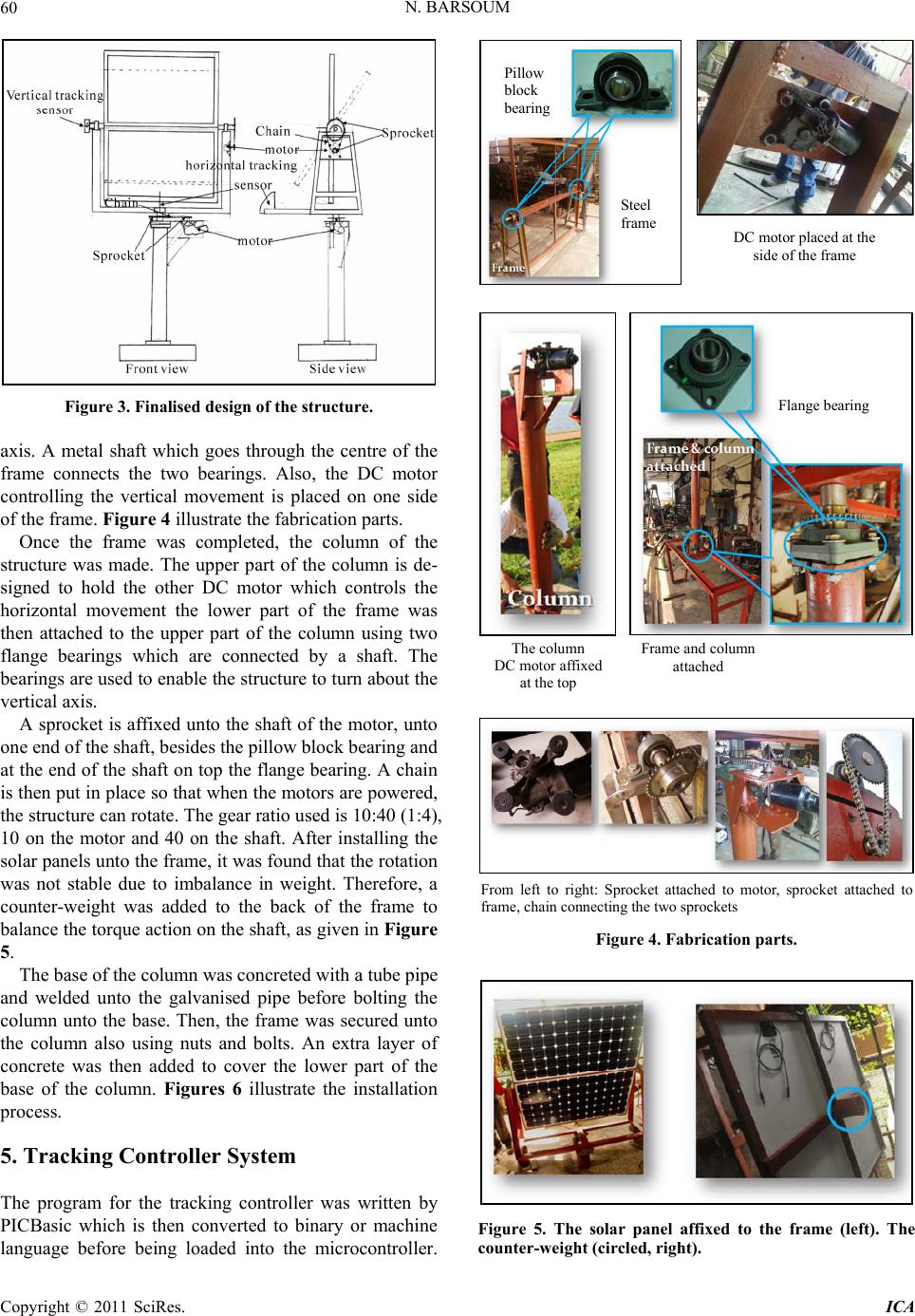 N. BARSOUM 60 Figure 3. Finalised design of the structure. axis. A metal shaft which goes through the centre of the frame connects the two bearings. Also, the DC motor controlling the vertical movement is placed on one side of the frame. Figure 4 illustrate the fabrication parts. Once the frame was completed, the column of the structure was made. The upper part of the column is de- signed to hold the other DC motor which controls the horizontal movement the lower part of the frame was then attached to the upper part of the column using two flange bearings which are connected by a shaft. The bearings are used to enable the structure to turn about the vertical axis. A sprocket is affixed unto the shaft of the motor, unto one end of the shaft, besides the pillow block bearing and at the end of the shaft on top the flange bearing. A chain is then put in place so that when the motors are powered, the structure can rotate. The gear ratio used is 10:40 (1:4), 10 on the motor and 40 on the shaft. After installing the solar panels unto the frame, it was found that the rotation was not stable due to imbalance in weight. Therefore, a counter-weight was added to the back of the frame to balance the torque action on the shaft, as given in Figure 5. The base of the column was concreted with a tube pipe and welded unto the galvanised pipe before bolting the column unto the base. Then, the frame was secured unto the column also using nuts and bolts. An extra layer of concrete was then added to cover the lower part of the base of the column. Figures 6 illustrate the installation process. 5. Tracking Co ntroller System The program for the tracking controller was written by PICBasic which is then converted to binary or machine language before being loaded into the microcontroller. Pillow block bearing Steel frame DC motor placed at the side of the frame Flange bearing The column DC motor affixed at the top Frame and column attached From left to right: Sprocket attached to motor, sprocket attached to frame, chain connecting the two sprockets Figure 4. Fabrication parts. Figure 5. The solar panel affixed to the frame (left). The counter-weigh t ( circled, right). Copyright © 2011 SciRes. ICA  N. BARSOUM61 Base of the column is welded and the column being set up The frame being attached to the column Applying an extra layer of concrete to the base Figure 6. Installation process. The microcontroller together with the controller circuit and the sensor will control the movement of the structure to track the sun. [4] Has chosen to use Microchip’s PIC16F84A microcontroller, given in Figures 7 and 8. The program and circuit has been developed by [4]. Each tracking axis has its own control circuit. To control the rotational direction of the motor, [4] used an H-Bridge. The works and writings of [2,12] have been referred to when making the following modifications to [4] program: Renaming symbols Reassigning ports Including limit switches Changing values of scales and time The algorithm is based on the classical basic language to detect the voltage signal from the light sensors and compare between 2 signals and calculate the different. This different is converted to set a certain position angle and send the signal to the motor to rotate precisely to an accurate position so that facing the sun. The program is too long and is not typed in this paper, but small part of the program is given below: Include "bs1defs.bas" Start: Symbol CDS1 = B0 Symbol CDS2 = B1 Symbol Diff = B6 TRISB.0 = 1 'set pin RB0 as input (sensor1) TRISB.1 = 1 'set pin RB1 as input (sensor2) TRISB.2 = 0 'set pin RB2 as output TRISB.3 = 0 'set pin RB3 as output Low PORTB.2 'pin RB2 set to low Low PORTB.3 'pin RB3 set to low Low PORTB.4 'pin RB4 set to low (limit-switch1) Low PORTB.5 'pin RB5 set to low (limit-switch2) The above description is: Symbols are declared and the input/output and variables are initialised. The code was written in PICBasic (saved as a .bas file) using Mi- croCode Studio. Within this software, the program code is then compiled and the .hex file is obtained. Figure 9 shows the MicroCode Studio. To load the program into the microcontroller, Micro- chip’s MPLAB IDE was used together with PICSTART Plus. Following the steps taken to set-up the PICSTART Plus programmer, Figures 10 and 11: Ensure that PICSTART Plus is powered and con- nected to the RS232 port of the computer. Open MPLAB IDE. Go to “configure > select device” and the corre- sponding microcontroller model was chosen. Click “ok”. Go to “programmer > select programmer” and “PIC- START Plus” was chosen. Figure 7. Pin setup for the PIC16F84A microcontroller. Copyright © 2011 SciRes. ICA 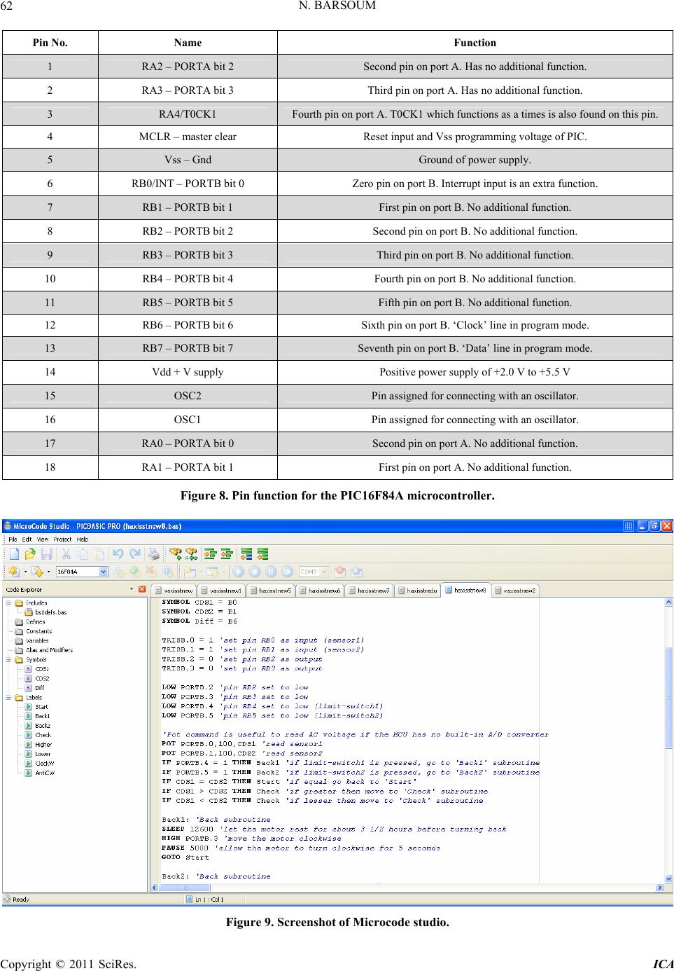 N. BARSOUM Copyright © 2011 SciRes. ICA 62 Pin No. Name Function 1 RA2 – PORTA bit 2 Second pin on port A. Has no additional function. 2 RA3 – PORTA bit 3 Third pin on port A. Has no additional function. 3 RA4/T0CK1 Fourth pin on port A. T0CK1 which functions as a times is also found on this pin. 4 MCLR – master clear Reset input and Vss programming voltage of PIC. 5 Vss – Gnd Ground of power supply. 6 RB0/INT – PORTB bit 0 Zero pin on port B. Interrupt input is an extra function. 7 RB1 – PORTB bit 1 First pin on port B. No additional function. 8 RB2 – PORTB bit 2 Second pin on port B. No additional function. 9 RB3 – PORTB bit 3 Third pin on port B. No additional function. 10 RB4 – PORTB bit 4 Fourth pin on port B. No additional function. 11 RB5 – PORTB bit 5 Fifth pin on port B. No additional function. 12 RB6 – PORTB bit 6 Sixth pin on port B. ‘Clock’ line in program mode. 13 RB7 – PORTB bit 7 Seventh pin on port B. ‘Data’ line in program mode. 14 Vdd + V supply Positive power supply of +2.0 V to +5.5 V 15 OSC2 Pin assigned for connecting with an oscillator. 16 OSC1 Pin assigned for connecting with an oscillator. 17 RA0 – PORTA bit 0 Second pin on port A. No additional function. 18 RA1 – PORTA bit 1 First pin on port A. No additional function. Figure 8. Pin function for the PIC16F84A microcontroller. Figure 9. Screenshot of Microcode studio. 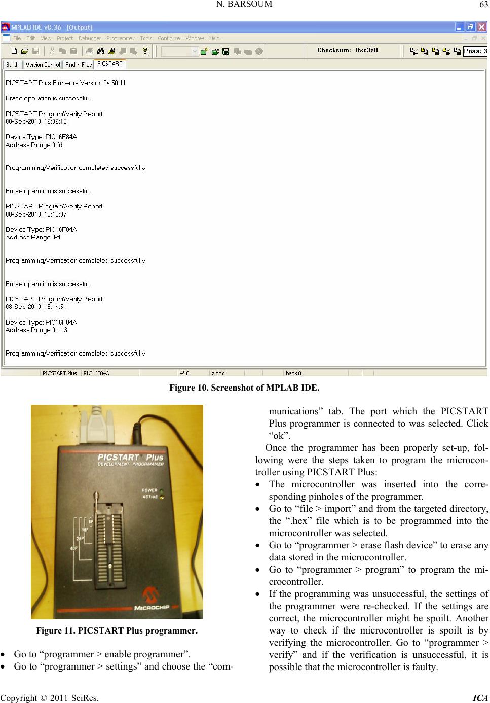 N. BARSOUM63 Figure 10. Screenshot of MPLAB IDE. Figure 11. PICSTART Plus programmer. Go to “programmer > enable programmer”. Go to “programmer > settings” and choose the “com- munications” tab. The port which the PICSTART Plus programmer is connected to was selected. Click “ok”. Once the programmer has been properly set-up, fol- lowing were the steps taken to program the microcon- troller using PICSTART Plus: The microcontroller was inserted into the corre- sponding pinholes of the programmer. Go to “file > import” and from the targeted directory, the “.hex” file which is to be programmed into the microcontroller was selected. Go to “programmer > erase flash device” to erase any data stored in the microcontroller. Go to “programmer > program” to program the mi- crocontroller. If the programming was unsuccessful, the settings of the programmer were re-checked. If the settings are correct, the microcontroller might be spoilt. Another way to check if the microcontroller is spoilt is by verifying the microcontroller. Go to “programmer > verify” and if the verification is unsuccessful, it is possible that the microcontroller is faulty. Copyright © 2011 SciRes. ICA 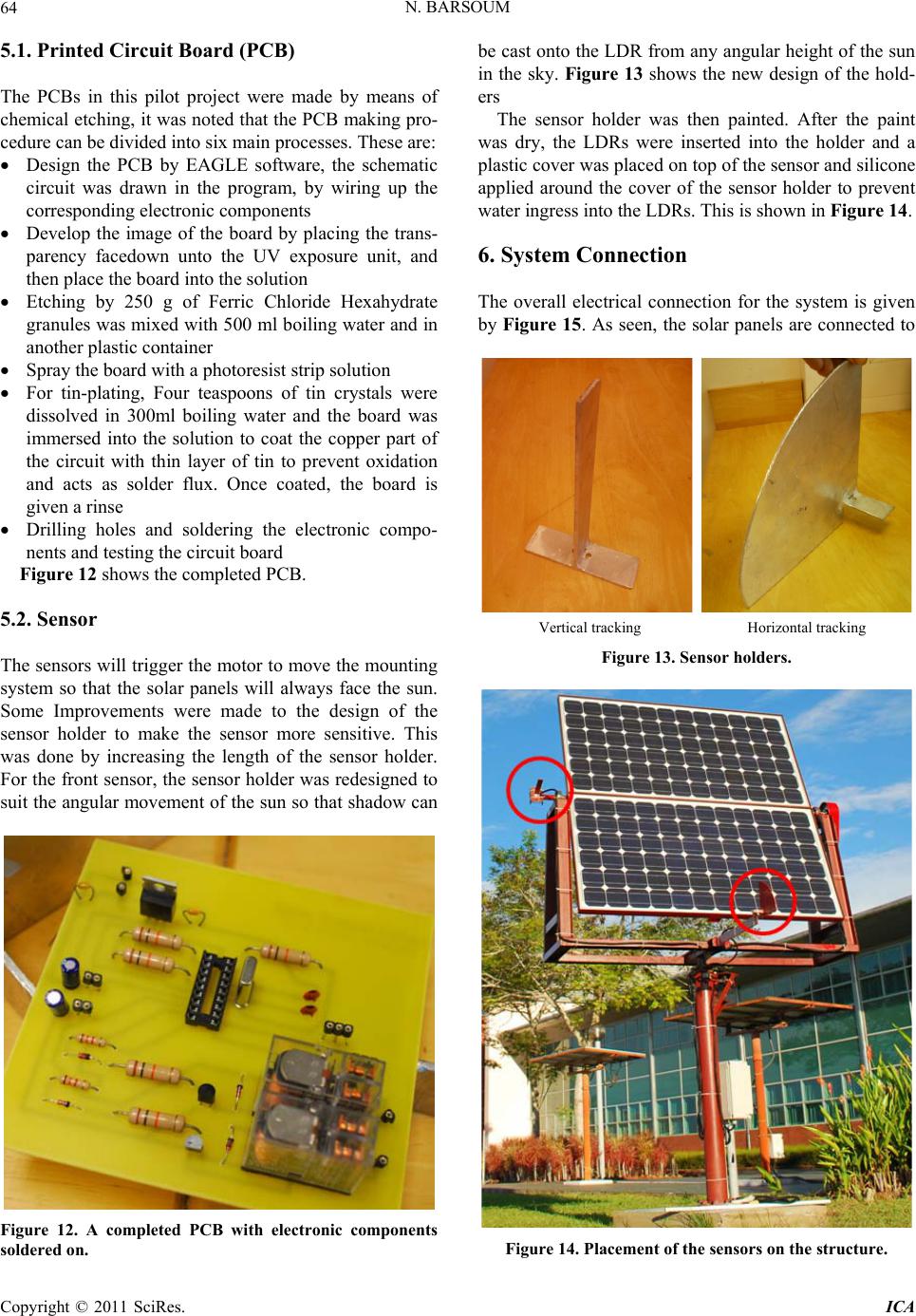 N. BARSOUM 64 5.1. Printed Circuit Board (PCB) The PCBs in this pilot project were made by means of chemical etching, it was noted that the PCB making pro- cedure can be divided into six main processes. These are: Design the PCB by EAGLE software, the schematic circuit was drawn in the program, by wiring up the corresponding electronic components Develop the image of the board by placing the trans- parency facedown unto the UV exposure unit, and then place the board into the solution Etching by 250 g of Ferric Chloride Hexahydrate granules was mixed with 500 ml boiling water and in another plastic container Spray the board with a photoresist strip solution For tin-plating, Four teaspoons of tin crystals were dissolved in 300ml boiling water and the board was immersed into the solution to coat the copper part of the circuit with thin layer of tin to prevent oxidation and acts as solder flux. Once coated, the board is given a rinse Drilling holes and soldering the electronic compo- nents and testing the circuit board Figure 12 shows the completed PCB. 5.2. Sensor The sensors will trigger the motor to move the mounting system so that the solar panels will always face the sun. Some Improvements were made to the design of the sensor holder to make the sensor more sensitive. This was done by increasing the length of the sensor holder. For the front sensor, the sensor holder was redesigned to suit the angular movement of the sun so that shadow can Figure 12. A completed PCB with electronic components soldered on. be cast onto the LDR from any angular height of the sun in the sky. Figure 13 shows the new design of the hold- ers The sensor holder was then painted. After the paint was dry, the LDRs were inserted into the holder and a plastic cover was placed on top of the sensor and silicone applied around the cover of the sensor holder to prevent water ingress into the LDRs. This is shown in Figure 14. 6. System Connection The overall electrical connection for the system is given by Figure 15. As seen, the solar panels are connected to Vertical tracking Horizontal tracking Figure 13. Sensor holders. Figure 14. Placement of the sensors on the structure. Copyright © 2011 SciRes. ICA 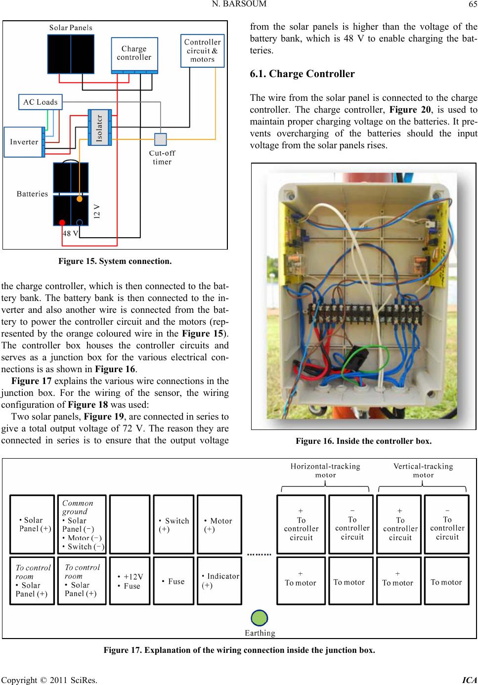 N. BARSOUM Copyright © 2011 SciRes. ICA 65 from the solar panels is higher than the voltage of the battery bank, which is 48 V to enable charging the bat- teries. 6.1. Charge Controller The wire from the solar panel is connected to the charge controller. The charge controller, Figure 20, is used to maintain proper charging voltage on the batteries. It pre- vents overcharging of the batteries should the input voltage from the solar panels rises. Figure 15. System connection. the charge controller, which is then connected to the bat- tery bank. The battery bank is then connected to the in- verter and also another wire is connected from the bat- tery to power the controller circuit and the motors (rep- resented by the orange coloured wire in the Figure 15). The controller box houses the controller circuits and serves as a junction box for the various electrical con- nections is as shown in Figure 16. Figure 17 explains the various wire connections in the junction box. For the wiring of the sensor, the wiring configuration of Figure 18 was used: Two solar panels, Figure 19, are connected in series to give a total output voltage of 72 V. The reason they are connected in series is to ensure that the output voltage Figure 16. Inside the controller box. Figure 17. Explanation of the wiring connection inside the junction box.  N. BARSOUM Copyright © 2011 SciRes. ICA 66 Figure 18. Connection of the coloured wires for the sensor. Figure 19. The solar panels. Figure 20. The charge controller. 6.2. Battery Bank Four 12 V batteries are connected in series to create a total output voltage of 48 V, shown in Figure 21. The wire from the charge controller is then connected to the battery bank which enables the batteries to be charged. From the battery bank, a wire is connected to the inverter. Then another wire is place on one of the 12 V batteries to power the 12 V DC loads such as the motors as well as the controller circuit. 6.3. Inverter, Isolator and Cut-off Timer The inverter, Figure 22, converts the 48 DC voltage of the battery to 230 AC single phase voltage to power AC loads. An isolator is put in place to make maintenance work on the system easier. Figure 21. The battery bank. Figure 22. The inverter. The cut-off timer, Figure 23, is a 24-hour based timer which allows electric current to pass through at pre-set times. The timer is powered using AC voltage from the inverter. The purpose of the timer is because the frame holding the solar panel has made more than one full rota- tion to the point that the cables were all twisted. Upon inspection, it was discovered that the sensor responded to the street lightings along lakeside which were lit after sunset. To overcome the problem, a cut-off timer was placed to cut-off the electricity supply to the controller circuit between just before sunset (around 6 p.m.) until 8 a.m. the next morning. This timer is adjustable. It was discovered that the structure did not rotate back to its original position just before sunset because the magnet never triggered the limit switch because they never came in contact. The position of the limit switch and the magnet was determined by noting the time and position when the horizontal tracking has reached its maximum for the day. However, due to the varying de- gree of movement of the sun in the sky throughout the year, the position of the limit switch and magnet for to- day is not the same as the position in three weeks time. To deal with this problem, the position of the limit switch was manually adjusted to correspond with the path of the setting sun. Another problem which occurred was rain water started to sip into the LDRs although the sensor holder has been covered with silicone. This was most probably due to inadequate silicone application. Hence, the sensor  N. BARSOUM67 Figure 23. 24-hour based timer switch. was taken apart and the LDRs replaced. This time, sili- cone was again applied to the sensor holder and an extra plastic sheet was put over the sensor. 6.4. Output and Loads The electricity output from the inverter is a single-phase sinusoidal 230 V AC voltage at 50 Hz. This was con- firmed and verified by connecting the output of the in- verter to an oscilloscope. Figure 24 shows the AC volt- age waveform. While the aim of this work was to create a dual-axis solar-tracking solar panel mount, nevertheless the elec- tricity output derived was tested on a few AC loads such as light bulbs, computer monitor and CPU, and a spot- light. Meanwhile, the AC voltage is also used to power the cut-off timer. The DC voltage derived from one of the 12 V batteries is used to power the controller circuit as well as the motors. 7. Suggestions It is suggested to: Apply grease to the gears and chains. Paint structure. Inspect for water ingress into controller box and sen- sor. Change plastic sheet over the sensor from time to time. Position of limit switches and magnet needs to be adjusted from time to time It is recommended to make this maintenance every 2 months or after every session of heavy rain, to check light sensors, timer sensors, all junctions, iron and cable connections 8. Conclusions The objective of this pilot project to design, fabricate and Figure 24. The voltage waveform of the output AC voltage form the inverter. install a solar panel mount with dual-axis sun tracking capability has been achieved. The work was made possi- ble through the cooperation and involvement of many different parties. Planning and communication skills were essential to ensure that the project went smoothly. There is still room for improvement for this system and it is hoped that further study can be carried out to further develop the system. Improvements can be done to the design of the structure, for example by adding covers for the motors and also improving the design of the sensor holder by making it waterproof. Besides that, improve- ments can be made to the current method of turning back the frame to its original position, removing the need to manually adjust the limit switches. Also, a detailed study should be carried out to ascertain the percentage increase of electricity yield by using this system to establish whether or not the system is viable. 9. References [1] M. R. Patel, “Wind and Solar Power Systems Design, Analysis and Operations,” 2nd Edition, CRC Press Taylor & Francis Group Producing a PCB. n.d., Boca Raton, 2006. http://uk.farnell.com/images/en_UK/design_findings8pt2. pdf [2] Solar Tracker, “Sun Path Diagram Image,” 2010. http://www.gaisma.com/en/location/miri.html, http://en.wikipedia.org/wiki/Solar_tracker [3] D. Appleyard, “Solar Trackers: Facing the Sun,” Renew- able Energy World, Vol. 12, No. 3, 2009. http://www.renewableenergyworld.com/rea/ne ws/article/ 2009/06/solar-trackers-facing-the-sun [4] N. Barsoum and P. Vasant, “Simplified Solar Tracking Prototype,” Global Journal of Technology and Optimiza- tion GJTO, Vol. 1, 2010, pp. 38-45. [5] J. Mak, “Personal Communication Messenger,” In: R. A. Copyright © 2011 SciRes. ICA 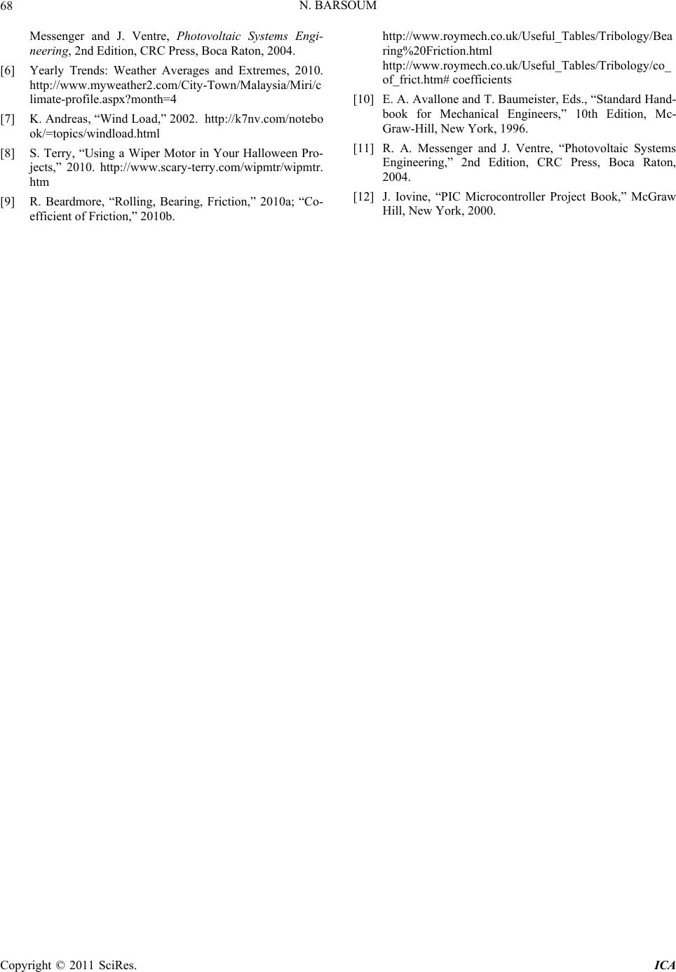 N. BARSOUM Copyright © 2011 SciRes. ICA 68 Messenger and J. Ventre, Photovoltaic Systems Engi- neering, 2nd Edition, CRC Press, Boca Raton, 2004. [6] Yearly Trends: Weather Averages and Extremes, 2010. http://www.myweather2.com/City-Town/Malaysia/Miri/c limate-profile.aspx?month=4 [7] K. Andreas, “Wind Load,” 2002.http://k7nv.com/notebo ok/=topics/windload.html [8] S. Terry, “Using a Wiper Motor in Your Halloween Pro- jects,” 2010. http://www.scary-terry.com/wipmtr/wipmtr. htm [9] R. Beardmore, “Rolling, Bearing, Friction,” 2010a; “Co- efficient of Friction,” 2010b. http://www.roymech.co.uk/Useful_Tables/Tribology /Bea ring%20Friction.html http://www.roymech.co.uk/Useful_Tables/Tribology /co_ of_frict.htm# coefficients [10] E. A. Avallone and T. Baumeister, Eds., “Standard Hand- book for Mechanical Engineers,” 10th Edition, Mc- Graw-Hill, New York, 1996. [11] R. A. Messenger and J. Ventre, “Photovoltaic Systems Engineering,” 2nd Edition, CRC Press, Boca Raton, 2004. [12] J. Iovine, “PIC Microcontroller Project Book,” McGraw Hill, New York, 2000. |