 Engineering, 2011, 3, 452-460 doi:10.4236/eng.2011.35052 Published Online May 2011 (http://www.SciRP.org/journal/eng) Copyright © 2011 SciRes. ENG Thin-Walled Tube Extension by Rigid Curved Punch Rostislav I. Nepershin Plastic Deformation Systems Department, Moscow State University of Technology “STANKIN”, Moscow, Russia E-mail: nepershin_ri@rambler.ru Received February 22, 2011; revised March 16, 2011; accepted March 31, 2011 Abstract Computer model is developed for non-steady and steady-state process of thin-walled tube extension by the rigid punch with curved profile. Rigid-plastic membrane shell theory with quadratic yield criterion is used. Tube material normal anisotropy, work hardening, wall thickness variation and friction effects are considered. FORTRAN programs of the model predict distributions of the thickness, meridian stress, yield stress and pressure along curved generator of deformed tube and the tube extension force versus punch displacement relation. Model predictions are correlated with experimental data. Keywords: Tube Extension, Rigid-Plastic Membrane Shell, Curved Rigid Punch, Normal Anisotropy, Work Hardening, Wall Thickness Variation 1. Introduction Thin-walled tube extension by rigid punch with curved generator can be used for forming of specified profiles at the tube ends defined by its function in machine design. Approximate analysis of the thin-walled tube extension by rigid punch is constrained, mainly, by conical form with approximate yield criterion of isotropic material, approximate wall thickness variation and work hardening effect [1-4]. Practical technology of the tube extension by cone punch reveals curved generators forming at tran- sition regions from cone to cylinder parts of the tube [2-4], which are difficult to control. But curved generator can be specified by hydro- or aerodynamic parameters of the tube profile. Thin-walled metal tube can reveals normal anisotropy induced by cold rolling technology with the result of stress-strain and wall thickness effects during tube extension. So, development of computer model of the tube extension process by rigid punch with curved generator and material normal anisotropy consid- eration, deems, is important engineering problem. Simulation of non-steady tube plastic forming by the finite element method (FEM) is limited by difficult problem of large matrix Equations accurate solution for nonlinear plastic material model with work hardening effect, stress-strain relations, variable shell thickness and curved tool boundary. Nonlinear plastic problem in commercial FEM codes is treated as non-linear elasticity or viscous solid without finite yield stress, with the result of non-accurate stress state calculations. More accurate simulation of thin-walled tube plastic forming, deems, should be made by correct numerical solution of ordinary differential Equation derived from exact equilibrium Equations of membrane rigid-plastic thin-walled shell model with Mises yield criterion, including work hard- ening and normal anisotropy effects. This approach was used successfully for non-steady models of plastic shells drawing, which good correlated with experiments [5-8], and for thin-walled tube reduction by matrix with curved profiles [9]. Presented model of the thin-walled tube extension by rigid punch with curved generator is based on membrane theory of the rigid-plastic shell of revolution, with mate- rial normal anisotropy, work hardening, wall thickness variation and friction effects included. FORTRAN pro- grams are written for numerical solution of the problem differential Equations. Numerical results of computer simulation are given for the S- mode cosine, double cir- cular and cone-circular punch profiles. Presented model for cosine punch profile and related model [9] for the tube reduction by curved matrix are reasonable corre- lated with experimental data. 2. Problem Formulation Scheme of the thin-walled tube extension by the punch with curved generator is shown in Figure 1. Cylindrical co-ordinates r, z, θ are related with fixed punch, while  R. I. NEPERSHIN453 the tube is moved in positive z direction. The punch curved profile is specified by differentiable function r = r (z) on the axial length H0 with continues tangent angle , defined by derivative ddrz = tg . The S- mode profile is considered with continues conjunction with cylinder surfaces of the tube with inner radius r0 at the point A, and the punch with maximal radius R0 at the point C. The angle = 0 at the points A and C, and = α at the maximum point ddz = 0. The profile curva- ture available should satisfy condition of continues punch-tube contact with positive pressure p, defined by solution of differential equilibrium Equation with plastic yield criterion. Plastic forming of the tube is generated by axial dis- placement s of the tube rigid part with initial wall thick- ness h0. Displacement s defines deformed tube segment AB. If s = l0 then point B of the tube edge is coincided with the final punch profile point C, where the tube plas- tic strain increase is stopped. Tube extension process is non-steady at the displacement interval 0 ≤ s ≤ l0 with the plastic strain increase and the wall thickness h de- crease on the curved tube segment AB. If s ≥ l0 then steady-state extension process begins, with accuracy of friction effect defined by slip of cylindrical tube segment with radius R0 on the punch surface. Tube extension ratio 00Rris constrained by the limit plastic strain ep* of tension in circular direction θ of the tube front edge which leads to local increase of the plas- tic strain followed by fracture of the tube edge. The ep* value is defined by material work hardening behavior [10]. Limit ratio00Rr, defined by the plastic strain ep*, is 1.2-1.3 for high plastic steel tube extension by cone punch [1,4]. Increase of the metal plasticity by heat of the deformed tube leads to essential increase of extension ratio [4]. In the case of tube extension at elevated tem- peratures the ideal plastic material model can be used with the yield stress estimation for mean strain rate and temperature values. Second constraint of the limit tube extension ratio is buckling of thin-walled initial tube induced by com- pression meridional stress σA at the section z = 0. De- tailed experimental investigations of cylindrical tube buckling are given in Refs [11,12]. Approximate esti- mations of the critical relation AS for the tube ex- tension by cone punch are given in Ref [4]. Critical buckling ratio of the tube can be increased essentially by kinematical constraints of the tube wall in tube ex- tension die design [4]. 3. Stress—Strain Relations In the case of thin-walled tube extension deformed mate- rial element of the tube middle surface is loaded by membrane principal stresses σ1 = σθ > 0 in circular direc- tion θ, σ2 = < 0 in meridian direction tangent to the punch profile, and σ3 = 0 in normal direction to the punch profile. Generalized Mises yield criterion for the principal stresses in the case of normal anisotropy in di- rection of the tube wall thickness can be written as fol- lows [7] 22 2 1 2 a a (1) Coefficient of normal anisotropy a is ratio of the width to thickness plastic strains defined by axial tension of sheet metal specimen [10]. Material yield stress σs is de- fined by accumulated plastic strain ep using work hard- ening relation 01n P Ce (2) Plastic flow rule associated with the yield criterion (1) defines increments of the plastic strains in and θ di- rections ddece , 1 1 aa caa (3) Accumulated effective plastic strain increment d eis defined by the and de increments using plastic incompressibility condition 22 2 1 d dddd 1 p a e eeee aa (4) Substitution relation deθ = drr and Equation (3) into Equation (4) defines dep as the function of the stress state and circular plastic strain increment 2 2 1d d1 1 p ar eссr aa (5) Plastic incompressibility condition and Equation (3) define differential relation for the wall thickness versus circular plastic strain increment and stress state coeffi- cient c d 1 h c hr dr (6) At the tube edge B (Figure 1) we have = 0, c = –(1 )aa , and wall thickness is found by integration of Equation (6) 00 0 2 1 exp ln 12 B BB rh hh arh (7) Extension process can be used to form of short ring with initial dimensions r0, h0, l0 to final dimensions R0, h, l, with the wall thickness h defined by Equation (7) 00 0 0 2 1 exp ln 12 rh hh aRh (8) Copyright © 2011 SciRes. ENG  R. I. NEPERSHIN Copyright © 2011 SciRes. ENG 454 and length l defined by constant volume condition 00 0 0 0 2 2 hr h ll hR h (9) Stress equilibrium Equations considered below will be solved using the yield criterion (1) to write positive cir- cular stress σθ as the function of meridian stress and yield stress σs 22 1112) 1s aa a a 2 (10) 4. Tube Stress State Stress state of deformed tube is calculated using mem- brane theory of the rigid-plastic shell with yield criterion (1), work hardening (2), wall thickness variation (6) and Coulomb’s friction coefficient f at the punch contact boundary specified by its generator. The shell element equilibrium equation in normal direction to the shell middle surface defines relation of the normal pressure p versus stresses σφ, σθ and the shell curvatures 21 ph RR (11) If punch generator is specified by the function r = r(z) then curvature radii are defined by the Equations 1 2 3/2 2 1 2 d 1d2 rh Rtgz ,d d r tg z (12) 2cos 2 r R h (13) From Equation (11) it is follows, that contact pressure p is positive if 21 RR (14) If inequality (14) is not satisfied, then the tube is de- parted from the punch profile, and curved free boundary of the tube is generated. Stress state of extended tube satisfies inequalities > 0 and < 0. Hence, the inequality (14) is defined by the tube stress state, values and signs of the punch profile radii R1 and R2. Tube stress state should satisfy equilibrium Equation in meridian direction to the middle surface, which for the case of variable wall thickness and Coulomb’s contact friction is written as follows: d0 dd sin dh pf rhr h (15) Substitution Equations (10) and (11) into Equation (15) gives differential Equation for the meridian stress , with specified distributions of the h and σs on the tube middle surface. If the punch profile is specified by the Equation r = r (z) with continues curvature radii defined by Equations (12) and (13), then integration of Equation (15) can be performed using z variable. In this case Equation (15) can be written in the form: 1 d1d dcosd tg fh tg zrRhzr (16) where σθ and R1 are defined by Equations (10) and (12). If concave and convex punch profile segments are speci- fied by circles radii r1 and r2 , then variable is rea- sonable for integration of Equation (15). Using relations dr = r1sin d , dr = r2sin d and Equation (11), differential Equation (15) can be written in the forms as Equation (17) on the concave profile segment, and Equa- tion (18) on the convex profile segment. If the punch profile is cone, conjugated with circles radii r1 and r2, then Equations (17) and (18) are used on the curved profiles, while the length l of cone generator, inclined at the angle α to the z axis, is used for integra- tion of Equation (15), which takes the form: dsin1 dsincos dd hf lrhlr (19) Simulation of non-steady tube extension by rigid punch is performed by numerical integration of Equa- tions (16)-(19) by second order Runge method with specified punch profile, and the tube front edge B mov- ing from the point A to the point C (Figure 1). Integra- tions are performed along the profile from the point B, where the boundary conditions are specified 00 0,,ln22 , sp pBB eerh rh (20) 11 11 d1d sinsincos , dd rr hh ff rhr 2 rr (17) 22 22 d1d sinsincos, dd rr hh ff rhr 2 rr (18)  R. I. NEPERSHIN455 and thickness hB is defined by Equation (7), to the point A , using distributions of the h, ep and σs known for pre- vious position of the point B, which is coincided with the point A at the initial process stage. Effective plastic strain increments dep are calculated from Equations (3) and (5) with material points displacements to the neighbouring nodes of the tube segment AB. Summering of the effec- tive plastic strain of material points and calculations of the σs and h from Equations (2), (6), define distributions of the σs and h for the next process stage. Calculations of non-steady stages are terminated when the point B is coincided with the point C, and steady-state tube exten- sion begins. Displacement s of initial tube is related with the edge point B position and wall thickness distribution by inte- gral incompressibility condition 00 0 12d 2cos B A r hhz hrh (21) Extension force P versus s is defined by maximum compression stress σA(s) = – (s) at the point A , which is found by integration of Equations (16)-(19) when point B is moving from the point A to the point C. 00 0 22 A Psr hhs (22) FORTRAN programs are written for computer simula- tion of the tube extension from initial radius r0 to the final radius R0 with three punch profiles specified on the length H0 of the z axis (Figure 1). Figure 1. Tube extension by the rigid curved punch. 5. Punch Profiles Cosine profile is specified by the function 00 0 0 1cosπ, 2 Rr z rr H 0 ≤ z ≤ H0 (23) First and second derivatives of the function (23), which defines the tangent angle and curvature radius R1 by Equation (12), are as follows 00 00 πsin π 2 Rr z tg H (24) 2 2 00 2 00 dπcosπ d2 Rr rz HH (25) Equations (23)-(25) are used for numerical integration of Equation (16) with constant step dz = 0–1HN , where N is number of nodes on the punch profile. Double circular profile is specified by circle radii r1 on the concave and r2 on the convex segments with tan- gent angle α at the bend point. The profile parameters r1, r2 and α satisfy the following relations 12 0 (1cos) rrR r 0 (26) 12 0 sinrr H (27) The angle α is found from Equations (26) and (27) in the form 2 2 sin 1 d d ,00 0 Rr dH (28) If radius r1 is specified and satisfy the inequality 0 1sin r , (29) then radius r2 can be found from Equation (27), and vice versa. So, double circular punch profile is defined by the parameters H0, R0, r0 and r1 or r2. The profile co-ordinates are specified in parametric form versus tan- gent angle 01 1 1cos ,sin,0rr rzr (30) On the concave segment, and 02 02 1cos ,sin,0rR rzHr (31) On the convex segment. Equations (30) and (31) are used for numerical integration of Equations (17) and (18) with constant step d =1N , where N is nodes num- ber on the each circular profile. Cone profile with circular conjunctions is specified by radii r1 and r2 on the curved concave and convex seg- ments, length L and angle α of the cone segment. The values r1, r2, L, α are related with H0, R0, r0 by the Equa- Copyright © 2011 SciRes. ENG  R. I. NEPERSHIN 456 tions 12 00 1cos sinrrLR r (32) 12 0 sin cosrrL H (33) If the angle α satisfy inequality 0 00 sin 1cos H Rr , (34) then L and radii sum are found from Equations (32) and (33) 00 0 sin 1cos LRr H (35) 0 12 cos sin HL rr (36) So, cone punch profile with circular conjunctions is defined by H0, R0, r0, α and radius r1 or r2. Co-ordinates of the profile are specified in parametric form versus by Equations (30) and (31) on the curved segments, and versus l on the cone segment 01 1 1 cossin,sincos ,rr rlzrl 0lL (37) Equations (30), (31) are used for numerical integration of Equations (17) and (18) with step d and nodes number N1 on the each curved segment. Equations (37) are used for numerical integration of Equation (19) on the cone segment with step dl =2LN , where N2 is nodes number on the cone profile segment. 6. Numerical Results Numerical results are presented for the tube extension simulations from initial radius r0 = 30 mm with wall thick- ness h0 = 1 mm to final radius R0 = 40 mm by three curved punch profiles on the length H0 = 25 mm. Tube material is low carbon steel with initial yield stress σ0 = 300 N/mm2 and work hardening parameters C = 1.27, n = 0.672. Cosine punch profile, defined by Equation (23), has continues curvature variation with radii r1 = r 2 = 12.67 mm at the points z = 0 and z = H0 and tangent angle α = 0.561 at the middle bend point. Double circular profile is specified by radii r1 = 15.0 mm, r2 = 21.25 mm and α = 0.761 at the bend point. Cone profile with circular con- jugations is specified by r1 = 12.0 mm, r2 = 14.22 mm, α = 0.5 and L = 14.16 mm of cone segment. Force P versus displacement s relations are shown in Figure 2 for three punch profiles with a =1 and f = 0.1, up to the steady state tube extension onset. Relations P(s) are S-mode curves with Pmax values 28.06, 27.91, 27.83 kN at the final s values l0 = 28.75, 30.33, 29.94 mm for (a) cosine, (b) double circular and (c) cone with circular conjunctions punch profiles. Close Pmax values are ex- plained by equal length H0, extension ratio 00 Rrand close curvature radii of the curved punch profile seg- ments. Distributions of accumulated effective plastic strain ep, meridian stress 0 – , contact pressure0s , wall thickness 0 hh and yield stress 00 Rralong deformed tube generator at the final extension stage are shown in Figure 3 for (a) cosine, (b) double circular and (c) cone with circular conjunctions punch profiles. Values ep, h/h0, 0s and 0 p at the front tube edge z = H0, where = 0, are defined by the final radius R0 for all punch profiles, with ep = 0.282, 0 hh = 0.868, 0s = 1.543 and 0 p = 3.31·10–2. Distributions of ep,0 hh , 0s are constrained by specified initial and final val- ues, and are close for three punch profiles considered. Contact pressure 0 p distributions are essentially Figure 2. Extension force P versus displacement s for (a) cosine; (b) double circular and (c) cone with circular con- junctions punch profiles. Copyright © 2011 SciRes. ENG 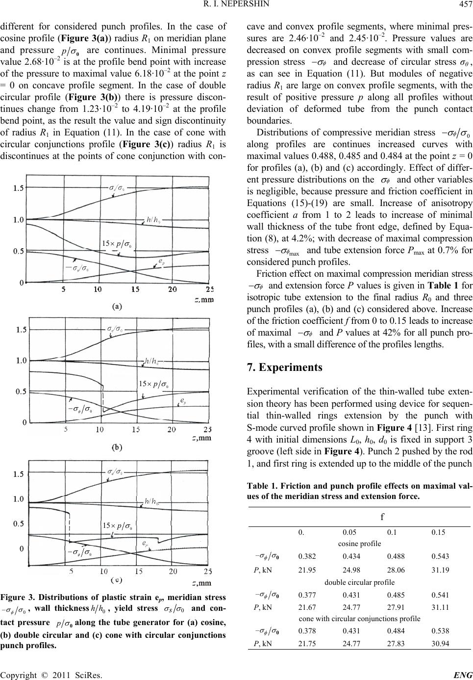 R. I. NEPERSHIN457 different for considered punch profiles. In the case of cosine profile (Figure 3(a)) radius R1 on meridian plane and pressure p 0 are continues. Minimal pressure value 2.68·10–2 is at the profile bend point with increase of the pressure to maximal value 6.18·10–2 at the point z = 0 on concave profile segment. In the case of double circular profile (Figure 3(b)) there is pressure discon- tinues change from 1.23·10–2 to 4.19·10–2 at the profile bend point, as the result the value and sign discontinuity of radius R1 in Equation (11). In the case of cone with circular conjunctions profile (Figure 3(c)) radius R1 is discontinues at the points of cone conjunction with con- 0 15 0 0 0 15 0 15 Figure 3. Distributions of plastic strain ep, meridian stress 0 – , wall thickness0 hh , yield stress 0s and con- tact pressure p 0along the tube generator for (a) cosine, (b) double circular and (c) cone with circular conjunctions punch profiles. cave and convex profile segments, where minimal pres- sures are 2.46·10–2 and 2.45·10–2. Pressure values are decreased on convex profile segments with small com- pression stress and decrease of circular stress σθ , as can see in Equation (11). But modules of negative radius R1 are large on convex profile segments, with the result of positive pressure p along all profiles without deviation of deformed tube from the punch contact boundaries. Distributions of compressive meridian stress 0 along profiles are continues increased curves with maximal values 0.488, 0.485 and 0.484 at the point z = 0 for profiles (a), (b) and (c) accordingly. Effect of differ- ent pressure distributions on the and other variables is negligible, because pressure and friction coefficient in Equations (15)-(19) are small. Increase of anisotropy coefficient a from 1 to 2 leads to increase of minimal wall thickness of the tube front edge, defined by Equa- tion (8), at 4.2%; with decrease of maximal compression stress max and tube extension force Pmax at 0.7% for considered punch profiles. Friction effect on maximal compression meridian stress and extension force P values is given in Table 1 for isotropic tube extension to the final radius R0 and three punch profiles (a), (b) and (c) considered above. Increase of the friction coefficient f from 0 to 0.15 leads to increase of maximal and P values at 42% for all punch pro- files, with a small difference of the profiles lengths. 7. Experiments Experimental verification of the thin-walled tube exten- sion theory has been performed using device for sequen- tial thin-walled rings extension by the punch with S-mode curved profile shown in Figure 4 [13]. First ring 4 with initial dimensions L0, h0, d0 is fixed in support 3 groove (left side in Figure 4). Punch 2 pushed by the rod 1, and first ring is extended up to the middle of the punch Table 1. Friction and punch profile effects on maximal val- ues of the meridian stress and extension force. f 0. 0.05 0.1 0.15 cosine profile – 0 0.382 0.434 0.488 0.543 P, kN 21.95 24.98 28.06 31.19 double circular profile – 0 0.377 0.431 0.485 0.541 P, kN 21.67 24.77 27.91 31.11 cone with circular conjunctions profile – 0 0.378 0.431 0.484 0.538 P, kN 21.75 24.77 27.83 30.94 Copyright © 2011 SciRes. ENG 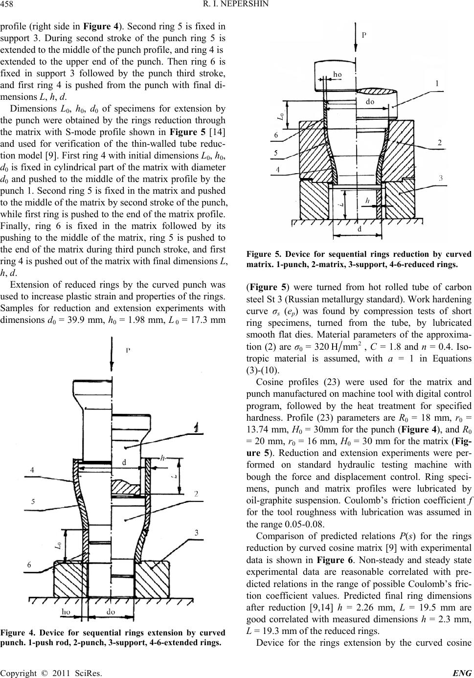 R. I. NEPERSHIN 458 profile (right side in Figure 4). Second ring 5 is fixed in support 3. During second stroke of the punch ring 5 is extended to the middle of the punch profile, and ring 4 is extended to the upper end of the punch. Then ring 6 is fixed in support 3 followed by the punch third stroke, and first ring 4 is pushed from the punch with final di- mensions L, h, d. Dimensions L0, h0, d0 of specimens for extension by the punch were obtained by the rings reduction through the matrix with S-mode profile shown in Figure 5 [14] and used for verification of the thin-walled tube reduc- tion model [9]. First ring 4 with initial dimensions L0, h0, d0 is fixed in cylindrical part of the matrix with diameter d0 and pushed to the middle of the matrix profile by the punch 1. Second ring 5 is fixed in the matrix and pushed to the middle of the matrix by second stroke of the punch, while first ring is pushed to the end of the matrix profile. Finally, ring 6 is fixed in the matrix followed by its pushing to the middle of the matrix, ring 5 is pushed to the end of the matrix during third punch stroke, and first ring 4 is pushed out of the matrix with final dimensions L, h, d. Extension of reduced rings by the curved punch was used to increase plastic strain and properties of the rings. Samples for reduction and extension experiments with dimensions d0 = 39.9 mm, h0 = 1.98 mm, L 0 = 17.3 mm 0 Figure 4. Device for sequential rings extension by curved punch. 1-push rod, 2-punch, 3-support, 4-6-extended rings. 0 Figure 5. Device for sequential rings reduction by curved matrix. 1-punch, 2-matrix, 3-support, 4-6-reduced rings. (Figure 5) were turned from hot rolled tube of carbon steel St 3 (Russian metallurgy standard). Work hardening curve σs (ep) was found by compression tests of short ring specimens, turned from the tube, by lubricated smooth flat dies. Material parameters of the approxima- tion (2) are σ0 = 3202 Hmm , C = 1.8 and n = 0.4. Iso- tropic material is assumed, with a = 1 in Equations (3)-(10). Cosine profiles (23) were used for the matrix and punch manufactured on machine tool with digital control program, followed by the heat treatment for specified hardness. Profile (23) parameters are R0 = 18 mm, r0 = 13.74 mm, H0 = 30mm for the punch (Figure 4), and R0 = 20 mm, r0 = 16 mm, H0 = 30 mm for the matrix (Fig- ure 5). Reduction and extension experiments were per- formed on standard hydraulic testing machine with bough the force and displacement control. Ring speci- mens, punch and matrix profiles were lubricated by oil-graphite suspension. Coulomb’s friction coefficient f for the tool roughness with lubrication was assumed in the range 0.05-0.08. Comparison of predicted relations P(s) for the rings reduction by curved cosine matrix [9] with experimental data is shown in Figure 6. Non-steady and steady state experimental data are reasonable correlated with pre- dicted relations in the range of possible Coulomb’s fric- tion coefficient values. Predicted final ring dimensions after reduction [9,14] h = 2.26 mm, L = 19.5 mm are good correlated with measured dimensions h = 2.3 mm, L = 19.3 mm of the reduced rings. Device for the rings extension by the curved cosine Copyright © 2011 SciRes. ENG 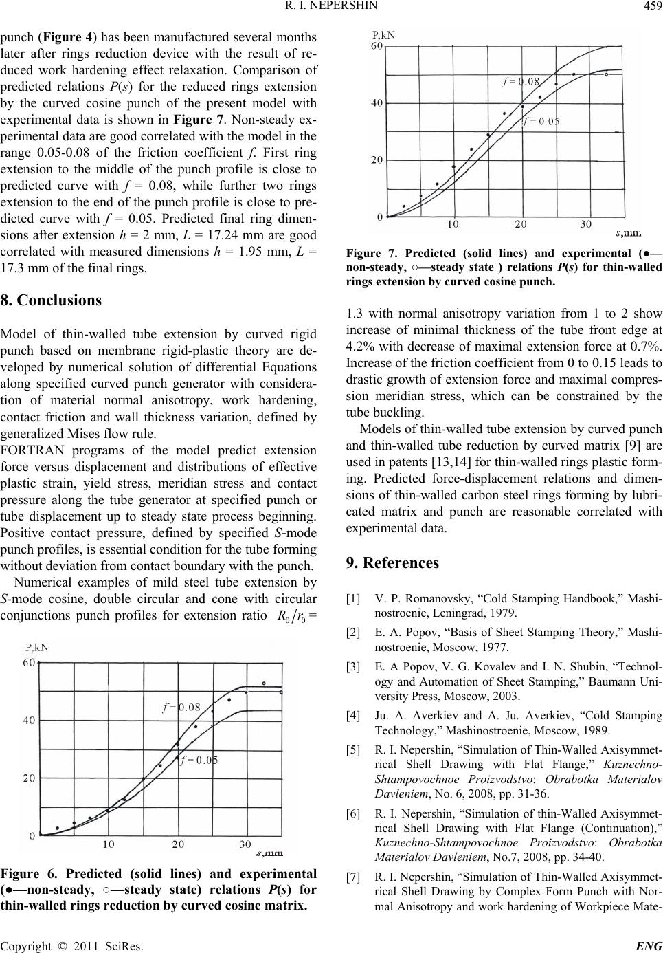 R. I. NEPERSHIN459 punch (Figure 4) has been manufactured several months later after rings reduction device with the result of re- duced work hardening effect relaxation. Comparison of predicted relations P(s) for the reduced rings extension by the curved cosine punch of the present model with experimental data is shown in Figure 7. Non-steady ex- perimental data are good correlated with the model in the range 0.05-0.08 of the friction coefficient f. First ring extension to the middle of the punch profile is close to predicted curve with f = 0.08, while further two rings extension to the end of the punch profile is close to pre- dicted curve with f = 0.05. Predicted final ring dimen- sions after extension h = 2 mm, L = 17.24 mm are good correlated with measured dimensions h = 1.95 mm, L = 17.3 mm of the final rings. 8. Conclusions Model of thin-walled tube extension by curved rigid punch based on membrane rigid-plastic theory are de- veloped by numerical solution of differential Equations along specified curved punch generator with considera- tion of material normal anisotropy, work hardening, contact friction and wall thickness variation, defined by generalized Mises flow rule. FORTRAN programs of the model predict extension force versus displacement and distributions of effective plastic strain, yield stress, meridian stress and contact pressure along the tube generator at specified punch or tube displacement up to steady state process beginning. Positive contact pressure, defined by specified S-mode punch profiles, is essential condition for the tube forming without deviation from contact boundary with the punch. Numerical examples of mild steel tube extension by S-mode cosine, double circular and cone with circular conjunctions punch profiles for extension ratio 00 Rr= Figure 6. Predicted (solid lines) and experimental (●—non-steady, ○—steady state) relations P(s) for thin-walled rings reduction by curved cosine matrix. Figure 7. Predicted (solid lines) and experimental (●— non-steady, ○—steady state ) relations P(s) for thin-walled rings extension by curved cosine punch. 1.3 with normal anisotropy variation from 1 to 2 show increase of minimal thickness of the tube front edge at 4.2% with decrease of maximal extension force at 0.7%. Increase of the friction coefficient from 0 to 0.15 leads to drastic growth of extension force and maximal compres- sion meridian stress, which can be constrained by the tube buckling. Models of thin-walled tube extension by curved punch and thin-walled tube reduction by curved matrix [9] are used in patents [13,14] for thin-walled rings plastic form- ing. Predicted force-displacement relations and dimen- sions of thin-walled carbon steel rings forming by lubri- cated matrix and punch are reasonable correlated with experimental data. 9. References [1] V. P. Romanovsky, “Cold Stamping Handbook,” Mashi- nostroenie, Leningrad, 1979. [2] E. A. Popov, “Basis of Sheet Stamping Theory,” Mashi- nostroenie, Moscow, 1977. [3] E. A Popov, V. G. Kovalev and I. N. Shubin, “Technol- ogy and Automation of Sheet Stamping,” Baumann Uni- versity Press, Moscow, 2003. [4] Ju. A. Averkiev and A. Ju. Averkiev, “Cold Stamping Technology,” Mashinostroenie, Moscow, 1989. [5] R. I. Nepershin, “Simulation of Thin-Walled Axisymmet- rical Shell Drawing with Flat Flange,” Kuznechno- Shtampovochnoe Proizvodstvo: Obrabotka Materialov Davleniem, No. 6, 2008, pp. 31-36. [6] R. I. Nepershin, “Simulation of thin-Walled Axisymmet- rical Shell Drawing with Flat Flange (Continuation),” Kuznechno-Shtampovochnoe Proizvodstvo: Obrabotka Materialov Davleniem, No.7, 2008, pp. 34-40. [7] R. I. Nepershin, “Simulation of Thin-Walled Axisymmet- rical Shell Drawing by Complex Form Punch with Nor- mal Anisotropy and work hardening of Workpiece Mate- Copyright © 2011 SciRes. ENG 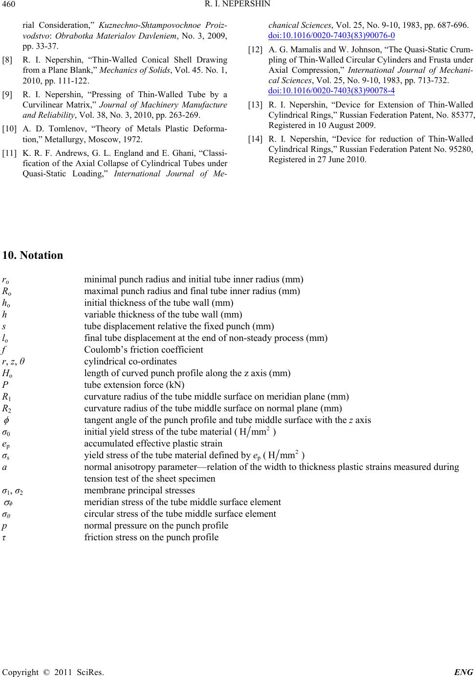 R. I. NEPERSHIN Copyright © 2011 SciRes. ENG 460 rial Consideration,” Kuznechno-Shtampovochnoe Proiz- vodstvo: Obrabotka Materialov Davleniem, No. 3, 2009, pp. 33-37. [8] R. I. Nepershin, “Thin-Walled Conical Shell Drawing from a Plane Blank,” Mechanics of Solids, Vol. 45. No. 1, 2010, pp. 111-122. [9] R. I. Nepershin, “Pressing of Thin-Walled Tube by a Curvilinear Matrix,” Journal of Machinery Manufacture and Reliability, Vol. 38, No. 3, 2010, pp. 263-269. [10] A. D. Tomlenov, “Theory of Metals Plastic Deforma- tion,” Metallurgy, Moscow, 1972. [11] K. R. F. Andrews, G. L. England and E. Ghani, “Classi- fication of the Axial Collapse of Cylindrical Tubes under Quasi-Static Loading,” International Journal of Me- chanical Sciences, Vol. 25, No. 9-10, 1983, pp. 687-696. doi:10.1016/0020-7403(83)90076-0 [12] A. G. Mamalis and W. Johnson, “The Quasi-Static Crum- pling of Thin-Walled Circular Cylinders and Frusta under Axial Compression,” International Journal of Mechani- cal Sciences, Vol. 25, No. 9-10, 1983, pp. 713-732. doi:10.1016/0020-7403(83)90078-4 [13] R. I. Nepershin, “Device for Extension of Thin-Walled Cylindrical Rings,” Russian Federation Patent, No. 85377, Registered in 10 August 2009. [14] R. I. Nepershin, “Device for reduction of Thin-Walled Cylindrical Rings,” Russian Federation Patent No. 95280, Registered in 27 June 2010. 10. Notation ro minimal punch radius and initial tube inner radius (mm) Ro maximal punch radius and final tube inner radius (mm) ho initial thickness of the tube wall (mm) h variable thickness of the tube wall (mm) s tube displacement relative the fixed punch (mm) lo final tube displacement at the end of non-steady process (mm) f Coulomb’s friction coefficient r, z, θ cylindrical co-ordinates Ho length of curved punch profile along the z axis (mm) P tube extension force (kN) R1 curvature radius of the tube middle surface on meridian plane (mm) R2 curvature radius of the tube middle surface on normal plane (mm) tangent angle of the punch profile and tube middle surface with the z axis σ0 initial yield stress of the tube material (2 Hmm ) ep accumulated effective plastic strain σs yield stress of the tube material defined by ep (2 Hmm ) a normal anisotropy parameter—relation of the width to thickness plastic strains measured during tension test of the sheet specimen σ1, σ2 membrane principal stresses meridian stress of the tube middle surface element σθ circular stress of the tube middle surface element p normal pressure on the punch profile τ friction stress on the punch profile
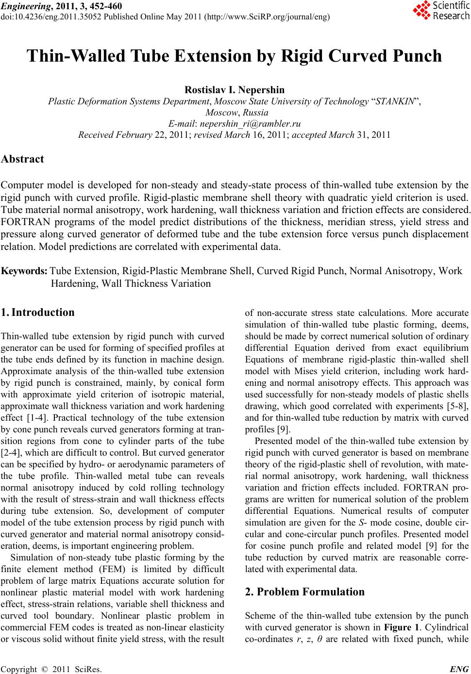
|