Engineering, 2011, 3, 445-451
doi:10.4236/eng.2011.35051 Published Online May 2011 (http://www.SciRP.org/journal/eng)
Copyright © 2011 SciRes. ENG
Improving Concrete Containment Structures Associated
with Fixed-Cone Valves
Bret Skyler Buck, Michael Clyde Johnson, Zachary Brad Sharp
Utah Water Research Laboratory (UWRL), Utah State University, Logan USA
E-mail: skyler.buck@aggiemail.usu.edu, michael.johnson@usu.edu, zac.sharp@aggiemail.usu.edu
Received March 3, 2011; revised March 29, 2011; accepted March 31, 2011
Abstract
Fixed-Cone valves are often used to dissipate energy and regulate flow at the low level outlet works of dams.
Fixed-Cone valves, also known as Howell-Bunger valves, create an expanding conical jet allowing the en-
ergy of the water to dissipate over a large area. However, in many applications constructing the large stilling
basin necessary for these valves is either not possible or not feasible. In order to reduce the relative size of
the stilling basin, hoods or concrete containment structures have been used in conjunction with Fixed-Cone
valves. This paper discusses the use of baffles in concrete containment structures in order to dissipate energy
in a considerably confined space. It was determined that using baffles, in place of a deflector ring and end sill
(Used in traditional containment structures), significantly improves the function of containment structures by
reducing downstream flow velocities and improving flow patterns and stability. This information will be
useful to engineers allowing them to minimize scour and erosion associated with concrete containment
structures.
Keywords: Valves, Containment Structure, Energy Dissipation, Concrete Erosion, Outlet Works
1. Introduction
The Howell-Bunger valve, also known as the Fixed-
Cone valve, is often used to reduce energy in the water
exiting the low level outlet works of a dam. This reduc-
tion of energy must happen in order to avoid erosion at
the toe of dam or in downstream channels. It is especially
important to reduce the velocity in the downstream
channel because velocity is the primary source of erosion
and scour.
Originally introduced by C. H. Howell and H. P.
Bunger in 1935, the valve consists of a conical Section
that is fixed in the end of the valve with a telescoping
sleeve that regulates flow. The valve causes the water
exiting to expand out radially creating a conical spray. It
is common for the water exiting the valve to exit at either
45 or 30 degrees measured from an axis that extends
perpendicular from the pipe. These valves are commonly
used to dissipate energy and regulate flow from the outlet
works of dams with medium (35 - 165 ft) to high (> 165
ft) heads. The Fixed-Cone valve is not only an excellent
energy dissipater, it is also is an excellent way to aerate
water discharged from impoundments. This is primarily
due to the fact that the water exiting a Fixed-Cone valve
expands out in every direction thus allowing a large flow
surface to be in contact with the atmosphere [1].
When used alone Fixed-Cone valves dissipate energy
effectively, however, due to the expanding conical jet,
relatively large stilling basins are required to capture the
excessive overspray. In many applications a large stilling
basin is either not possible or not feasible. In order to
reduce the size of the stilling basin, hoods and concrete
containment structures have been used in conjunction
with Fixed-Cone valves. In applications with medium
heads, hoods are often used in conjunction with Fixed-
Cone valves creating a concentrated hollow jet. When
the hood is attached to the valve it is referred to as a
Ring-Jet valve. However, Ring-Jet valves and Hooded
Fixed-Cone valves still require a considerable sized
stilling basin in order to avoid having a scouring effect
take place downstream. In order to dissipate more energy
the hoods can be lined with baffles. The combination of a
Fixed-Cone valve and a baffled hood are capable of dis-
sipating up to 95 percent of the power upstream from the
valve [2].
The United States Bureau of Reclamation (USBR) has
several designs using Howell-Bunger valves in conjunc-
tion with reinforced concrete containment structures. The
B. S. BUCK ET AL.
446
containment structures vary in size and cross- sectional
shape, but maintain the same general design and similar
structural elements. These containment structures usually
include an aeration hatch, a Fixed-Cone valve, and a de-
flector ring followed by an end sill or baffle piers. When
in operation this valve produces a conical jet that strikes
the walls of the containment structure at approximately
45 degree angles (only if a 90 degree cone is used). After
contact most of the flow continues along the surface until
the deflector ring redirects the flow to a common point
downstream [3].
The USBR has employed these concrete containment
structures at a number of dams including: LG-2 Devel-
opment (Quebec, Canada), Portage Mountain Dam (Brit-
ish Columbia, Canada), Ute Dam (New Mexico, USA),
New Waddell Dam (Arizona, USA), Stony Gorge Dam
(California, USA), and Jordanelle Dam (Utah, USA). It
has been noted that the structure at Jordanelle Dam has a
considerable amount of overspray even at low flows. The
concrete containment structure at the LG-2 development
consists of two Fixed-Cone Valves discharging into a
common chamber of oval cross-Section with a deflector
ring followed by a row of floor baffles [4]. The Portage
Mountain Dam structure has a circular cross-Section, but
in all other regards is the same as the LG-2 structure [5].
The Ute dam has a chamber cross-Section that is oc-
tagonal, followed by the deflector ring and an end sill
instead of the floor baffles [6]. The other dams listed
have containment structures with rectangular cross-Sec-
tions deflector rings and end sills [4].
2. Experiments
A study was conducted at Utah State University at the
Utah Water Research Laboratory (UWRL) to determine
if there was a more effective and economical contain-
ment structure that could be used with Fixed-Cone
valves. A fixed cone valve having 7.8-inch fixed cone
diameter and an exit angle of 45 degrees was used for
these tests. Six different models were constructed and
compared for this study. Figure 1 shows the two differ-
ent containment structure cross-sections (with their re-
spective dimensions) used for this research, with the di-
mensions standardized in terms of valve diameter (D).
Each cross-Section had three configurations that were
tested. The first configuration used a deflector ring and
an end sill. Figure 2 shows the profile and plan views of
the standard containment structure configuration de-
scribed previously with deflector ring and end sill. The
other two configurations used the baffles shown in Fig-
ure 3 instead of the deflector ring and end sill, the only
difference being that the last two rows of baffles shown
in Figure 4 were removed for the third configuration.
Once again, note that all dimensions were normalized in
terms of the valve diameter in order to easily apply them
to any desired prototype. Plywood painted with a latex
paint was the construction material used to simulate the
concrete containment structures, the deflector ring and
the end sill while Plexiglas was used to make the baffles.
The six models were run through four different model
reservoir heads with five different flow rates for each
reservoir head. The model reservoir heads for this ex-
periment were 15.4D, 23.1D, 30.8D, and 38.5D.
Figure 1. Cross-sections of containment structures.
Figure 2. Containment structure with deflector ring and
end sill in cross-Section 1.
Figure 3. Standard baffle A and corner baffle B.
Copyright © 2011 SciRes. ENG
B. S. BUCK ET AL.
Copyright © 2011 SciRes. ENG
447
Figure 4. Baffle containment structure with extra two rows of baffles in cross-section 2.
3. Evaluation Criteria *100
if
di
HH
EH



(1)
All previous research and model studies focused solely
on adequate energy dissipation and observations. These
are both valid and important criteria and are hence in-
cluded in this study. However, in order to more thor-
oughly evaluate the performance of the model contain-
ment structures downstream velocities and the down-
stream flow patterns were also taken into account. These
two criterions are of utmost importance. Undesirable
flow patterns, including non-uniform flow and unstable
hydraulic jumps, require additional design considerations
for the downstream channel. These considerations could
represent a considerable cost both in time and structures
to ameliorate the channel. High velocity flows are of
highest significance when considering scour and erosion
of material. In this study average velocities in the down-
stream channel were used for comparison. In order to
calculate these velocities the flows were divided by the
product of the average depth of flow and the width of the
downstream channel. The flow patterns were qualita-
tively recorded by noting any hydraulic jumps, flow pat-
terns or irregularities.
i
H
and
f
H
are calculated using Equation (2) where
the energy head or total head (H) is calculated employing
the following form of the Bernoulli Equation:
2
2
PV
HZ
g
 (2)
where H is the total head, P is the pipe pressure at the
inlet of the Howell-Bunger valve, γ is the specific weight
of water, Z is the elevation of the water above datum, g
is the acceleration due to gravity, and V is the average
velocity. The elevation datum for the water was taken as
the bottom of the containment structure. The initial head
was calculated from measurements made upstream of the
Howell-Bunger valve using a precision pressure gage to
measure the pipe pressure and a calibrated magnetic flow
meter to measure the flow rate. The final head was cal-
culated using the same flow rate found upstream of the
Howell-Bunger valve and a channel depth. The down-
stream water depth was taken as the average of three
depths (at 0.25, 0.5, and 0.75 the width of the channel)
which were measured using a point gauge downstream
from the containment structure. Measurements were also
taken for the geometry of the different containment
structures (cross-Section 1 or cross-Section 2), the per-
The amount of energy dissipated (d) is calculated
using Equation (1), and is given as a percentage of the
initial energy head (i
E
H
) minus the final energy head
(
f
H
) over the initial head.
B. S. BUCK ET AL.
448
cent valve opening, and the velocity of air entering
though the aeration hatch.
4. Results
It was originally planned to record a baseline dissipation
measurement using cross-Section 1 without any of the
energy dissipation structures installed. However, the wa-
ter exiting the structure was moving at a high rate of ve-
locity and was far too turbulent to get any valid readings.
This visually confirmed the fact that simply changing the
direction of the jet from a Fixed-Cone valve does little as
far as power (energy) dissipation is concerned [2].
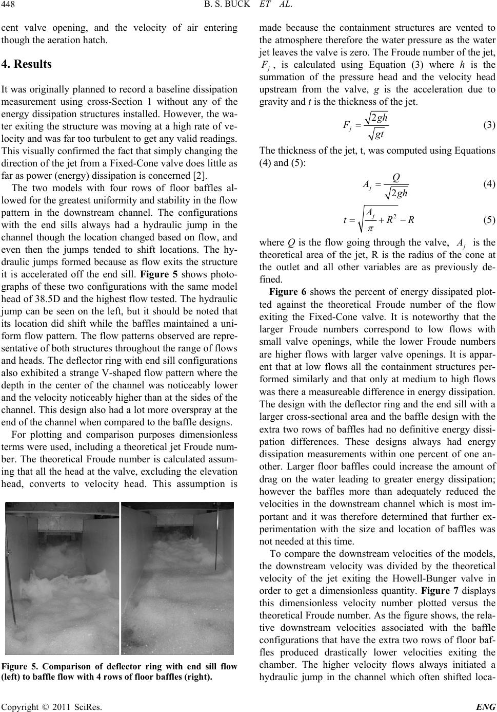
The two models with four rows of floor baffles al-
lowed for the greatest uniformity and stability in the flow
pattern in the downstream channel. The configurations
with the end sills always had a hydraulic jump in the
channel though the location changed based on flow, and
even then the jumps tended to shift locations. The hy-
draulic jumps formed because as flow exits the structure
it is accelerated off the end sill. Figure 5 shows photo-
graphs of these two configurations with the same model
head of 38.5D and the highest flow tested. The hydraulic
jump can be seen on the left, but it should be noted that
its location did shift while the baffles maintained a uni-
form flow pattern. The flow patterns observed are repre-
sentative of both structures throughout the range of flows
and heads. The deflector ring with end sill configurations
also exhibited a strange V-shaped flow pattern where the
depth in the center of the channel was noticeably lower
and the velocity noticeably higher than at the sides of the
channel. This design also had a lot more overspray at the
end of the channel when compared to the baffle designs.
For plotting and comparison purposes dimensionless
terms were used, including a theoretical jet Froude num-
ber. The theoretical Froude number is calculated assum-
ing that all the head at the valve, excluding the elevation
head, converts to velocity head. This assumption is
Figure 5. Comparison of deflector ring with end sill flow
(left) to baffle flow with 4 rows of floor baffles (right).
made because the containment structures are vented to
the atmosphere therefore the water pressure as the water
jet leaves the valve is zero. The Froude number of the jet,
F
, is calculated using Equation (3) where h is the
summation of the pressure head and the velocity head
upstream from the valve, g is the acceleration due to
gravity and t is the thickness of the jet.
2
j
g
h
F
g
t
(3)
The thickness of the jet, t, was computed using Equations
(4) and (5):
2
jQ
A
g
h
(4)
2
j
A
tR
R
 (5)
where Q is the flow going through the valve,
A
is the
theoretical area of the jet, R is the radius of the cone at
the outlet and all other variables are as previously de-
fined.
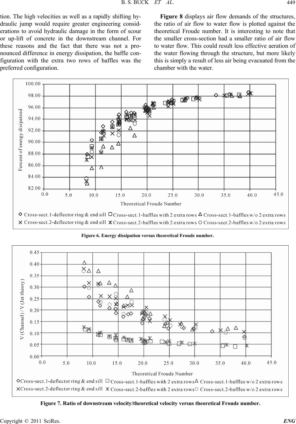
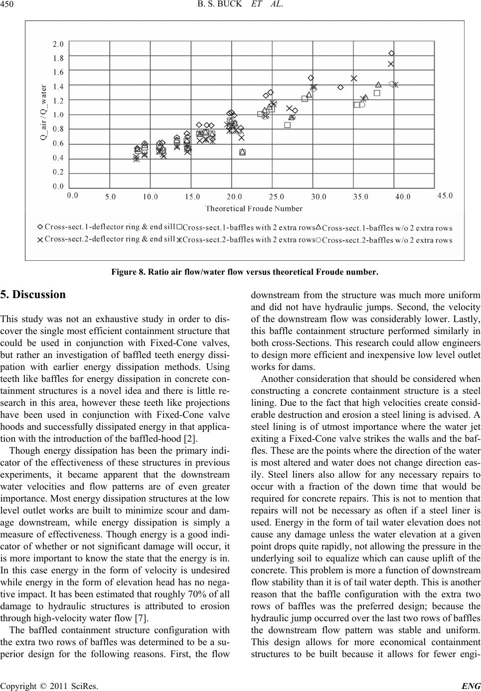
Figure 6 shows the percent of energy dissipated plot-
ted against the theoretical Froude number of the flow
exiting the Fixed-Cone valve. It is noteworthy that the
larger Froude numbers correspond to low flows with
small valve openings, while the lower Froude numbers
are higher flows with larger valve openings. It is appar-
ent that at low flows all the containment structures per-
formed similarly and that only at medium to high flows
was there a measureable difference in energy dissipation.
The design with the deflector ring and the end sill with a
larger cross-sectional area and the baffle design with the
extra two rows of baffles had no definitive energy dissi-
pation differences. These designs always had energy
dissipation measurements within one percent of one an-
other. Larger floor baffles could increase the amount of
drag on the water leading to greater energy dissipation;
however the baffles more than adequately reduced the
velocities in the downstream channel which is most im-
portant and it was therefore determined that further ex-
perimentation with the size and location of baffles was
not needed at this time.
To compare the downstream velocities of the models,
the downstream velocity was divided by the theoretical
velocity of the jet exiting the Howell-Bunger valve in
order to get a dimensionless quantity. Figure 7 displays
this dimensionless velocity number plotted versus the
theoretical Froude number. As the figure shows, the rela-
tive downstream velocities associated with the baffle
configurations that have the extra two rows of floor baf-
fles produced drastically lower velocities exiting the
chamber. The higher velocity flows always initiated a
hydraulic jump in the channel which often shifted loca-
Copyright © 2011 SciRes. ENG
B. S. BUCK ET AL.
Copyright © 2011 SciRes. ENG
449
Figure 8 displays air flow demands of the structures,
the ratio of air flow to water flow is plotted against the
theoretical Froude number. It is interesting to note that
the smaller cross-section had a smaller ratio of air flow
to water flow. This could result less effective aeration of
the water flowing through the structure, but more likely
this is simply a result of less air being evacuated from the
chamber with the water.
tion. The high velocities as well as a rapidly shifting hy-
draulic jump would require greater engineering consid-
erations to avoid hydraulic damage in the form of scour
or up-lift of concrete in the downstream channel. For
these reasons and the fact that there was not a pro-
nounced difference in energy dissipation, the baffle con-
figuration with the extra two rows of baffles was the
preferred configuration.
Figure 6. Energy dissipation versus theoretical Froude number.
Figure 7. Ratio of downstream velocity/theoretical velocity versus theoretical Froude number.
B. S. BUCK ET AL.
450
Figure 8. Ratio air flow/water flow versus theoretical Froude number.
5. Discussion
This study was not an exhaustive study in order to dis-
cover the single most efficient containment structure that
could be used in conjunction with Fixed-Cone valves,
but rather an investigation of baffled teeth energy dissi-
pation with earlier energy dissipation methods. Using
teeth like baffles for energy dissipation in concrete con-
tainment structures is a novel idea and there is little re-
search in this area, however these teeth like projections
have been used in conjunction with Fixed-Cone valve
hoods and successfully dissipated energy in that applica-
tion with the introduction of the baffled-hood [2].
Though energy dissipation has been the primary indi-
cator of the effectiveness of these structures in previous
experiments, it became apparent that the downstream
water velocities and flow patterns are of even greater
importance. Most energy dissipation structures at the low
level outlet works are built to minimize scour and dam-
age downstream, while energy dissipation is simply a
measure of effectiveness. Though energy is a good indi-
cator of whether or not significant damage will occur, it
is more important to know the state that the energy is in.
In this case energy in the form of velocity is undesired
while energy in the form of elevation head has no nega-
tive impact. It has been estimated that roughly 70% of all
damage to hydraulic structures is attributed to erosion
through high-velocity water flow [7].
The baffled containment structure configuration with
the extra two rows of baffles was determined to be a su-
perior design for the following reasons. First, the flow
downstream from the structure was much more uniform
and did not have hydraulic jumps. Second, the velocity
of the downstream flow was considerably lower. Lastly,
this baffle containment structure performed similarly in
both cross-Sections. This research could allow engineers
to design more efficient and inexpensive low level outlet
works for dams.
Another consideration that should be considered when
constructing a concrete containment structure is a steel
lining. Due to the fact that high velocities create consid-
erable destruction and erosion a steel lining is advised. A
steel lining is of utmost importance where the water jet
exiting a Fixed-Cone valve strikes the walls and the baf-
fles. These are the points where the direction of the water
is most altered and water does not change direction eas-
ily. Steel liners also allow for any necessary repairs to
occur with a fraction of the down time that would be
required for concrete repairs. This is not to mention that
repairs will not be necessary as often if a steel liner is
used. Energy in the form of tail water elevation does not
cause any damage unless the water elevation at a given
point drops quite rapidly, not allowing the pressure in the
underlying soil to equalize which can cause uplift of the
concrete. This problem is more a function of downstream
flow stability than it is of tail water depth. This is another
reason that the baffle configuration with the extra two
rows of baffles was the preferred design; because the
hydraulic jump occurred over the last two rows of baffles
the downstream flow pattern was stable and uniform.
This design allows for more economical containment
structures to be built because it allows for fewer engi-
Copyright © 2011 SciRes. ENG
B. S. BUCK ET AL.451
neering considerations and structures in the downstream
channel (including riprap), it allows for smaller
cross-Sections without dramatic changes in performance,
and less maintenance reconstruction due to scour. In cer-
tain applications these reductions in cost could be con-
siderable. With further interest and experimentation it
would be possible to provide a design guide to those in-
terested in designing more efficient Fixed-Cone valve
containment structures.
7. References
[1] G. L. Beichley, “Hydraulic Model Studies of Scoggins
Dam Fishtrap Aeration and Supply Structure,” USBR
REC-ERC-72-27, 1972.
[2] M. C. Johnson and R. Dham, “Innovative En-
ergy-Dissipating Hood,” Journal of Hydraulic Engineer-
ing, Vol. 138, No. 8, 2006, pp. 759-764.
doi:10.1061/(ASCE)0733-9429(2006)132:8(759)
[3] T. E. Helper and H. W. Peck, (1989). “Energy Dissipa-
tion Structure for Fixed-Cone Valves,” Proceedings of
the 1989 National Conference on Hydraulic Engineering,
New Orleans, 14-18 August 1989, pp. 956-961.
[4] D. Colgate, “Hydraulic Model Studies of the Low-Level
Outlet Works, LG-2 Development. Quebec, Canada,”
USBR REC-ERC-74-3, 1974.
[5] G. L. Beichley, “Hydraulic Model Studies of Portage
Mountain Low Level Outlet Works,” USBR Report No
Hyd-508, 1966.
[6] G. L. Beichley, “Hydraulic model studies of an Energy
Dissipator for a Fixed-Cone Valve at the Ute Dam Outlet
Works,” USBR REC-OCE-70-11, 1970.
[7] Y. Yin, D. Cui and X. Hu, “Study of Wear Performance
of Hydraulic Concrete under High Speed Clear Water
Jet,” Chinese Science Abstracts, Vol. 6, No. 9, 2000, pp.
1181-1182.
Copyright © 2011 SciRes. ENG