Circuits and Systems
Vol.07 No.10(2016), Article ID:70254,11 pages
10.4236/cs.2016.710289
A Resonant Dual Full-Bridge Class-E Bidirectional DC-DC Converter for Fuel Cell Electric Vehicle
Kuppan Senthil1*, Dr. Daniel Mary2
1Department of Electrical and Electronics Engineering, Adhiyamaan College of Engineering, Hosur, India
2Department of Electrical Engineering, Government College of Technology, Coimbatore, India

Copyright © 2016 by authors and Scientific Research Publishing Inc.
This work is licensed under the Creative Commons Attribution International License (CC BY).
http://creativecommons.org/licenses/by/4.0/


Received 7 April 2016; accepted 14 April 2016; published 31 August 2016
ABSTRACT
The interests on energy storage schemes, bidirectional dc-dc converter and uninterruptible power supplies have been increasing nowadays as there wide researches are undertaken in the area of electric vehicles. A modified bi directional class-E resonant dc-dc converter is introduced here in this proposed topology for the application in electric vehicles. The advantages of soft switching techniques have been utilized for making analysis simple. The main advantage here in this system is that it can operate in a wide range of frequencies with minimal switching loss in transistors. This paper elaborates a detailed analysis on converter design and the same has been simulated and verified in Matlab/Simulink.
Keywords:
Bidirectional DC-DC, Fuel Cell, Electric Vehicle, Resonant Converter

1. Introduction
During the last few decades, the impact on environment by the petroleum based transportation has driven towards electric motor based transportation. The electric vehicle [1] - [3] differs from the petroleum based vehicles in the sense that the electrical energy consumed by the electrical motor [4] can be generated by means of various and wide range of sources like nuclear energy, renewable energies and also from fossil fuels. The electrical energy then may be stored in any forms like super capacitors or batteries.
Hence due to the increased interest on the electric vehicles, the studies and researches are also growing in the area of energy storage systems [4] , bi directional dc-dc converter [2] and uninterruptible power supplies [5] [6] (Figure 1). Conventionally, the dual active bridge converter [7] was used for this application, but this converter cannot achieve zero voltage switching [8] in varies range of load variations when input and output voltage rises. Hence to eliminate this problem in control system the phase shift [9] [10] was introduced with the pulse width modulation.
Also a bidirectional dc-dc converter [11] - [13] is realized by a current fed inverter on the low voltage side of the transformer and voltage fed inverter on the high voltage side of the transformer [14] - [16] . But all the conventional converters are pertaining to the dissatisfactions in terms of switching loss and inability to achieve zero voltage switching during wide load variations. The drawbacks in the above said conventional types are eradicated in the proposed resonant based bidirectional dc-dc converter.
2. Proposed BDC Scheme and Operation Principle
The proposed system consists of two full bridge bidirectional current source class-E converter (Figure 2). A transformer with secondary to primary turns ratio KT transforms the energy between two converters. Since the low voltage side converter transistors are controlled, the converter operates as a class-E boost converter [17] and the high voltage side converter operates as a class-E rectifier with transistor body diode since it is not controlled. The combination made by inductance Lr, capacitance CL and capacitance CH, becomes a resonance circuit.
Likewise when the power flow takes place from VH to VL, the HV side converter operates as a class-E buck converter [18] . Since they are controlled and as the LV side converter transistors are not controlled, the converter acts as a class-E rectifier. Now the resonance circuit is formed by the capacitance CL and the inductance Lr. In order to realise the Zero Voltage Switching (ZVS) in a class-E resonant converter, it has to be controlled by a frequency change by keeping a constant break between the switching pulses of the transistor as in the case of quasi resonant converter. Both the LV side boost operation and HV side buck operation are characterized by an overlap or break of control pulse of the transistor pairs located diagonally in the bridge.
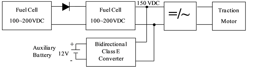
Figure 1. Block diagram of fuel-cell electric-bus’s energy managing structure.

Figure 2. Proposed bidirectional class-E converter.
3. Design of Converter and Performance Analysis
A maximum power is transferred during LV boost motoring mode at the optimal operation point whereas a minimum power is transferred during the HV side. The main criteria in designing this converter are the calculation of capacitors in LV and HV side of the bidirectional current DC boost converter.
3.1. HV-Buck Charging Mode
During the HV buck charging mode, the motor is subjected to a back EMF greater than the source and as a result a high generated energy is then buck by the converter to enable the battery to charge. The Zero Voltage Switching is achieved in the converter due to CL, low voltage side capacitance. The energy charged in the battery can be used by the dc to dc bidirectional converter when the motor is in the motoring mode.
The converter current IH available during the input motoring performance and the output current iH of the converter is sinusoidal and the marked portion but a part of ISC is flowing through the transistor and the unmarked portion describes that a part of iSC is flowing through the capacitor CH. Initially the capacitor CH is charging from zero voltage and when the current changes its direction the ISC gets discharged to zero voltage in the capacitor CH. Then the iSC can be described as
 (1)
(1)
The following equations are fulfilled the ZVS condition.
 (2)
(2)
where δ is the transistor control pulse width.
During the steady state operation, the desired value of the capacitance CH is calculated by assuming the mean value of the capacitor CH voltage is equal to the half value of the source voltage VH.
 (3)
(3)
 (4)
(4)
3.2. LV-Boost Motoring Mode
The low voltage is boosted by the bidirectional dc to dc converter by taking the advantage of high voltage side capacitor CH. the resulted boost energy is then used by the motor to achieve motoring performance. During the motoring performance the back EMF will be lower than the supply voltage.
Likewise as in the analysis of buck converter [18] , the value of capacitance CL is calculated for the boost converter. Thus the relation of the input IL to the output current ILM of the boost converter is given by
 (5)
(5)
4. Matlab/Simulink Simulation and Results
Simulation is carried through Matlab/Simulink software with an aid of Sim-Power System block sets. Modelled simulation is solved through ode 25 tb solver with 2 µs of discrete sample time in power Graphical User Interface (GUI) settings. A complete simulation model of a proposed system is shown in Figure 3. Dual full bridge was constructed by use of MOSFET from Sim-Power System block set with parallel capacitors to form the resonant tank circuits. Also a battery and PMDC motor are modelled form Sim-Power System block sets.
The proposed system is simulated by using the following specifications: Battery source VL = 12 V, HV side of PMDC motor on 150 V dc with 2.5 Hp. Control frequency range of 200 kHz. Shunt capacitors for LV side CL = 40 nF and the shunt capacitors for HV side is CH = 3.5 nF. The values of the capacitance are decided based on the Equations (4) and (5).

Figure 3. Matlab/Simulink simulation model.
Parasitic inductance causes oscillations in the transistor current waveforms. Simulation is modelled over 20 sec, in which first 10 sec for motoring mode by applying position torque. After 10sec load torque is changed into negative sign. Hence the machine is work as a generator and charge the battery by buck mode. The simulation result of load voltage shown in Figure 4, which shows that the energy transferring is taking place from the battery source to the load for a period of 10 sec because the VL is less than 150 V. Hence the power flow from left to right and the load current and torque are in positive sign during this period. During this period, battery works in discharging mode and the PMDC works in motoring mode.
The 2.5 Hp load consumes the current 2.5 amps and motor reaches the rated speed of 1500 rpm as shown in Figure 5 and Figure 6 respectively during the period of motoring mode (0sec to 10 sec). During this motoring mode the load torque is maintained at 2.5 N-m as shown in Figure 7.
Similarly the simulation results are represents the charging mode (buck operation when machine work as a generator) when the back emf is greater than 150 V dc (Figure 4), during above the rated speed (Figure 6) and the energy transferring is taking place from load to battery for a period of 10sec to 20sec. During this period battery gets charged, which can be identified by the direction of the current flowing from load to battery (negative sign) as shown in Figure 5 and also the torque goes negative as shown in Figure 7.
During the motoring mode, the battery delivers a constant voltage of 12V to the load through boost converter and current also maintained a rated value for 2.5 HP load for a period up to 10sec as shown in Figure 8 and Figure 9. Figure 10 show the State Of Charging (SOC) of a battery which discharge the power and hence the SOC is start to reducing from 0sec to 10sec of motoring mode. During the buck mode, battery gets charged by 14volt and battery current goes negative for a period of 10sec to 20sec as shown in Figure 8 and Figure 9. Figure 10 show the SOC is increased due to charging of battery during the buck mode for 10sec to 20sec. The performance of the battery is validated by simulation results.
The Zero Voltage Switching (ZVS) for the converter is achieved due to the capacitors CL and CH. Figure 11 illustrates switching performance during resonance conditions. The switch S2 is turned ON at 0.015sec as shown in Figure 11(a) voltage across the switch is maintained at zero as shown in Figure 11(b). At the starting time the current in the switch is zero (Figure 11(c)) and starts rising over the time. Power frequency is limited by the availability of isolated transistor drivers for bridge systems. This research work introduces and verifies the idea of application of class-E converters for bidirectional power flow.
5. Experimental Implementation and Results
The prototype hardware of the proposed method experimental setup implementation block diagram is shown in the Figure 12. LV-boost converter and HV-buck converter are implemented by using IRF630 transistor. A toroidal core transformer is used to link the LV and HV converter. The propylene capacitors for CH = 3.5 nF and CL = 40 nF is used to make resonant tank. A 12 V battery is used to store the energy available during charging and deliver the power to motor during motoring mode.

Figure 4. Load voltage during motoring and charging mode.

Figure 5. Load current during motoring and charging mode.

Figure 6. Motor speed during motoring and charging mode.

Figure 7. Motor torque during motoring and charging mode.

Figure 8. Battery voltage during motoring and charging mode.

Figure 9. Battery current during motoring and charging mode.

Figure 10. SOC of a battery during motoring and charging mode.
 (a)
(a) (b)
(b) (c)
(c)
Figure 11. Switching performance during resonance conditions. (a) Switching gate pulse; (b) Voltage across switch; (c) Current flow through the switch.

Figure 12. Block diagram of experimental implementation.
A 150 V, 2.5 Hp PMDC motor is connected in with HV side of converter. Required gate pulses of the transistors are generated from PIC16F877A microcontroller. The gate pulses are in the amplitude of 5V TTL, hence they are magnified through individual gate drivers and they are separated by isolators. A Digital Storage Oscilloscope (DSO) is used to observe the real time performance of the battery, motor and converters. Figure 13 show the photo snap of the experimental implementation setup.
Special arrangements are made for every measurement to observe DSO while hardware is running. Motor voltage and current are shown in Figure 14. Motor voltage and current are observed through attenuation probe and shown in channel-1 for 100 V/div and channel-2 for 10 A/div respectively. Time of the DSO shows 2 sec/div, hence upto first 10 sec performance shows motoring mode after 10 sec to 20 sec shows charging mode. Figure 15 shows experimental result of motor speed. The motor speed is measured through tacho generator and the speed equivalent voltage generation is observed through attenuation probe of DSO. Channel-1 of speed measurement shows 1250 rpm/div for both motoring and charging mode.
The battery performance of the experimental implementation is shown in Figure 16 for both battery voltageand current observed from attenuation probe of DSO. Channel-1 shows 10V/div of battery voltage and chan-

Figure 13. Snapshot of experimental implementation.

Figure 14. Experimental results for motor voltage and current.
nel-2 shows 125 A/div of battery current. From the observation after 10 sec, battery voltage is increased in to 14 V and the current is turned into negative to charge the battery.
Soft switching performance (ZVS) of the converter is analysed by observation of gate pulse of the switch and the corresponding voltage and current of the switch. Figure 17 show the gate pulse of the switch which is generated from PIC micro controller and hence it is in the amplitude range of 5 V TTL (5 V/div) and switching frequency of 200 kHz. Respective voltage across the switch is shown in Figure 18 which shows the voltage (90 V/div) across the switch is zero when the switch is triggered and turned off. Figure 19 shows the current flow (0.5 A/div) through the switch when it’s triggered and turned off. From the observation of the obtained experimental results, they are similar in every manner with the simulated results hence the hardware implementation is validated.

Figure 15. Experimental result for motor speed.

Figure 16. Experimental result for battery voltage and current.

Figure 17. Experimental result for gate plus.

Figure 18. Experimental result for voltage across the switch.

Figure 19. Experimental result for current flow through the switch.
6. Conclusion
The proposed BDC has many distinguished features like simple topology and reliable control strategy. Additionally with BDC the ZVS for all the switches and soft commutation for the rectifier diode over a wide load range can be easily achieved. As a result the power loss problem and the diode reverse recovery problem are resolved even for high power applications with greater efficiency. The experimental results demonstrate the validity of the simulated analysis.
Cite this paper
Kuppan Senthil,Dr. Daniel Mary, (2016) A Resonant Dual Full-Bridge Class-E Bidirectional DC-DC Converter for Fuel Cell Electric Vehicle. Circuits and Systems,07,3392-3402. doi: 10.4236/cs.2016.710289
References
- 1. Fukui, K. and Koizumi, H. (2012) Class E Rectifier with Controlled Shunt Capacitor. IEEE Transactions on Power Electronics, 27, 3704-3713.
http://dx.doi.org/10.1109/TPEL.2012.2184560 - 2. Jalbrzykowski, S., Bogdan, A. and Citko, T. (2011) A Dual Full-Bridge Resonant Class-E Bidirectional DC-DC Converter. IEEE Transactions on Industrial Electronics, 58, 3879-3883.
http://dx.doi.org/10.1109/TIE.2010.2100335 - 3. Williams, R. and Grabowski, W. (1998) Single Package 30-V Battery Disconnect Switch Facilities Battery Multiplexing in Notebook Computers. Proceedings of the IEEE APEC, 691-699.
- 4. Baalbergen, F., Bauer, P. and Ferreira, J. (2009) Energy Storage and Power Management for Typical 4Q-Load. IEEE Transactions on Industrial Electronics, 56, 1485-1498.
http://dx.doi.org/10.1109/TIE.2009.2012416 - 5. Hayati, M., Lotfi, A., Kazimierczuk, M.K. and Sekiya, H. (2014) Modeling and Analysis of Class-E Amplifier with a Shunt Inductor at Sub-Nominal Operation for Any Duty Ratio. IEEE Transactions on Circuits and Systems, 61, 987- 1000.
http://dx.doi.org/10.1109/tcsi.2013.2283692 - 6. Hayati, M., Lotfi, A., Kazimierczuk, M.K. and Sekiya, H. (2013) Performance Study of Class-E Power Amplifier with a Shunt Inductor at Subnominal Condition. IEEE Transactions on Power Electronics, 28, 3834-3844.
http://dx.doi.org/10.1109/TPEL.2012.2227814 - 7. Lee, S.H., Park, C.Y., Kwon, J.M. and Kwon, B.H. (2015) Hybrid-type Full-bridge DC/DC Converter with High Efficiency. IEEE Transactions on Power Electronics, 30, 4156-4164.
http://dx.doi.org/10.1109/TPEL.2014.2360404 - 8. Jose, P. and Mohan, N. (2003) A Novel ZVS Bidirectional Cuk Converter for Dual Voltage Systems in Automobiles. Proceedings of the 29th Annual IEEE IECON, 2-6 November 2003, 117-122.
http://dx.doi.org/10.1109/iecon.2003.1279965 - 9. Xu, D., Zhao, C. and Fan, H. (2004) A PWM plus Phase-Shift Control Bidirectional DC-DC Converter. IEEE Transactions on Power Electronics, 19, 666-675.
http://dx.doi.org/10.1109/TPEL.2004.826485 - 10. Xiao, H. and Xie, S. (2008) A ZVS Bidirectional DC-DC Converter with Phase Shift plus PWM Control Scheme. IEEE Transactions on Power Electronics, 23, 813-823.
http://dx.doi.org/10.1109/TPEL.2007.915188 - 11. Tao, H., Duarte, J.L. and Hendrix, A.M. (2008) Three-Port Triple-Half-Bridge Bidirectional Converter with Zero-Vol- tage Switching. IEEE Transactions on Power Electronics, 23, 782-792.
http://dx.doi.org/10.1109/TPEL.2007.915023 - 12. Ma, G., Qu, W., Yu, G., Liu, Y., Liang, N. and Li, W. (2009) A Zero-Voltage Switching Bidirectional DC-DC Converter with State Analysis and Soft Switching-Oriented Design Consideration. IEEE Transactions on Industrial Electronics, 56, 2174-2184.
http://dx.doi.org/10.1109/TIE.2009.2017566 - 13. Li, H. and Peng, F.Z. (2004) Modeling of a New ZVS Bi-Directional DC-DC Converter. IEEE Transactions on Aerospace and Electronic Systems, 40, 272-283.
http://dx.doi.org/10.1109/TAES.2004.1292159 - 14. Ja?brzykowski, S. and Citko, T. (2008) Current-Fed Resonant Full-Bridge Boost DC/AC/DC Converter. IEEE Transactions on Industrial Electronics, 55, 1198-1205.
http://dx.doi.org/10.1109/TIE.2007.909084� - 15. Ja?brzykowski, S. and Citko, T. (2003) Bridge Configuration of Class-E Converters. Archives of Electrical Engineering, 52, 221-237.�
- 16. Kazimierczuk, M.K. and Czarkowski, D. (1995) Resonant Power Converters. Wiley-Inter Science, New York.
- 17. Ray, B. (1992) Bidirectional DC-DC Power Conversion Using Quasi-Resonant Topology. Proc. IEEE Annual Power Electronics Specialists Conference, 617-624.
http://dx.doi.org/10.1109/pesc.1992.254825 - 18. Chan, H.L., Cheng, K.W.E. and Sutanto, D. (2003) ZCS-ZVS Bi-Directional Phase-Shifted DC-DC Converter with Extended Load Range. IEE Proceedings—Electric Power Applications, 150, 269-277.
http://dx.doi.org/10.1049/ip-epa:20030256
NOTES

*Corresponding author.