Journal of Electromagnetic Analysis and Applications
Vol. 5 No. 2 (2013) , Article ID: 28507 , 5 pages DOI:10.4236/jemaa.2013.52012
A Novel Compact Microstrip Elliptical Patch Resonator Filter with Tunable Bandwidth
![]()
Department of Electrical and Computer Engineering, University of Colorado, Colorado Springs, USA.
Email: *hsong@uccs.edu
Received December 9th, 2012; revised January 11th, 2013; accepted January 22nd, 2013
Keywords: Elliptical Patch; Bandpass Filter; Tunable Bandwidth; Microstrip Resonator; Flexible Filter
ABSTRACT
A novel elliptical patch resonator for a compact bandpass filter with tunable bandwidth is presented. This bandpass filter has the advantage of great flexibility in which the center frequency can be changed easily. The bandwidth of this filter can be modified by simply changing one variable, and this makes the proposed design unique. The order of the elliptical patch resonator can be increased, and three types of different orders of the same design are compared. The proposed filter can be used for future compact advanced wireless communication systems.
1. Introduction
Most of the microstrip bandpass filters are designed for fixed center frequency and bandwidth which makes these filters only useful for certain operating conditions. There are some different techniques used to build microstrip bandpass filters with fixed center frequency and bandwidth, and some of these techniques are very complex. Some microstrip filters use resonator due to its excellent response [1-3]. Few researchers were able to control the bandwidth of the bandpass filter at a fixed center frequency by using complementary split ring resonator (CSRR) [4]. However, little effort has been made to implement tunable frequency and bandwidth.
Communication systems require filters with tunable center frequency and bandwidth. In order to meet this requirement, filters need to go through complex dimension changes or need to be operated with different control devices for center frequency and bandwidth tuning. The control devices are such as varactor diodes, PIN diodes, and MEMS switches, and these devices control the electrical length of resonators, which changes the bandwidth and frequency. The devices are used with microstrip PCB in the same circuit. The disadvantages of that are the noise associated with lumped elements and can be burned if the input power is high. A variety of different techniques were used to build tunable filter with the control devices [5-9].
In this paper, we propose a novel microstrip filter that has a capability of tuning the center frequency and bandwidth without complex dimension changes nor using varactor diode. The proposed filter can be tuned by slightly modifying a few parameters in the design. One variable needs to be changed for bandwidth tuning and two variables need changing for center frequency tuning. In addition, the size of the proposed filter is compact, and it depends on the center frequency.
The design, fabrication, and characterization of the proposed filter are described. Analytical calculations and 3D electromagnetic simulations were carried out to determine the shape and the dimensions of the filter. Effects of different filter dimensions and configurations were investigated to determine the optimum filter response. The proposed filter was fabricated on a Rogers RO4003 material and the measurement results were compared with the designed results.
2. Filter Design and Simulation
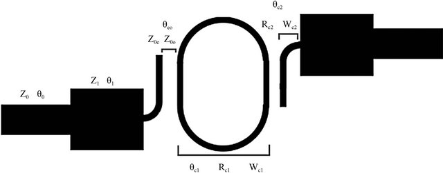
The geometry of the proposed microstrip bandpass filter is shown in Figure 1. In view of this geometry, two patch resonators represents low pass and high pass filters, and they are fed by pair of feed lines with two stepped impedances to create bandpass filter. The filter needs two patch resonators in order to achieve bandpass characteristics. Figure 1(a) contains a feed line of 50 Ohms, stepped impedance, a coupled line, and a curved bend. The feed line of 50 Ohms is connected at each side, and it is used to match input to output. The stepped impedance is linked between the feed lines and coupled lines. The curved bends are united between the coupled lines to create elliptical patch resonator. The purpose of using
 (a)
(a) (b)
(b)
Figure 1. Schematic and equivalent circuit of the bandpass filter. (a) Schematic layout; (b) Equivalent circuit.
coupled lines is to easily control dimensions for bandwidth tuning.
An equivalent circuit of the design is shown in Figure 1(b), and the matching networks are shown in the beginning and end of the circuit. Boxes in the middle of the equivalent circuit represent coupled lines of two orders. In Figure 1, Z0, Z1, θ0, and θ1 represent characteristics impedances and angles of the feed line and stepped impedance, and Z0o, Z0e, and θeo represent the characteristic impedances and angle of the coupled line for the odd and even mode. For the curved bend, θc1, θc2, Rc1, Rc2, Wc1, and Wc2 represent angles, radius, and width of the curved bend.
The values of the parameters in Figure 1(a) are shown in Table 1.
Mathematical expressions used in the design process are shown below:
 (1)
(1)
Equivalent capacitance circuits for odd and even modes for coupled lines are shown in Figure 2.
Capacitance (Ce) and characteristic impedance equations for even mode are shown in Equations (2) and (3) [10].
 (2)
(2)
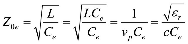 (3)
(3)
Table 1. Parameter values for this filter design.
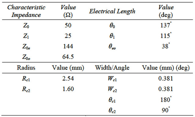
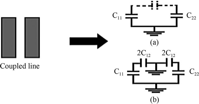
Figure 2. Coupled line and the resulting equivalent capacitance networks. (a) Even mode; (b) Odd mode.
where c is the speed of light, C11 and C22 are capacitors for the coupled line Equations for capacitance (Co) and characteristic impedance for odd mode are shown in Equations (4) and (5) [10].
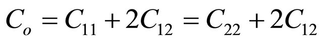 (4)
(4)
 (5)
(5)
Therefore, by using Equations (3) and (5), capacitances of even and odd modes are found to be 42.5 pF and 95 pF for the proposed filter.
A schematic of the proposed filter is created in Advanced Design Systems (ADS) [11] to generate a simulation. Insertion loss (S21) and return loss (S11) of the proposed filter are presented in Figure 3.
Figure 3 shows the simulation response for the filter showing the insertion loss close to 0 dB and the return loss of −10 dB. Center frequency of the proposed elliptical patch resonator filter was 9.24 GHz with a bandwidth of 22%.
The spacing of the coupled lines can be changed in order to control the bandwidth of the proposed filter. The spacing of the coupled lines is referred to “S” as shown in Figure 4.
When the spacing of coupled lines changes, the characteristic impedances for even and odd modes changes as well. As the spacing decreases, the characteristic impedance for the even mode increases and decreases for the odd mode. The bandwidth of the proposed filter becomes wider as the spacing decreases due to strong coupling coefficient. A relationship between the characteristic impedances for even and odd modes and coupling coefficient are shown in Equation (6) [10].

Figure 3. The simulated insertion loss (S21) and return loss (S11) of the proposed filter.

Figure 4. Variable parameters in controlling the bandwidth and center frequency of the proposed filter.
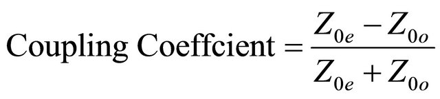 (6)
(6)
The bandwidth of this filter can be changed easily by increasing the spacing (S) of the two-coupled lines by the same amount. The filter insertion loss change as a function of frequency for different values of “S” is displayed in Figure 5.
When the spacing of the coupled lines increases, the bandwidth becomes narrower. Therefore, the bandwidth is considered to be a function of the spacing of the coupled lines. Table 2 shows the bandwidth change for different values of spacing of the coupled line.
Table 2 shows that the proposed filter can be tuned to exhibit different bandwidths by only changing one variable associated with the coupled lines.
If the elliptical patch resonator increases in size, the center frequency shifts to lower a frequency. In order to achieve this, the length of coupled lines (L) and radius of the curved bend (Rc) as shown in Figure 4 must increase. The effect of “L” and Rc change on filter insertion loss is shown in Figure 6.
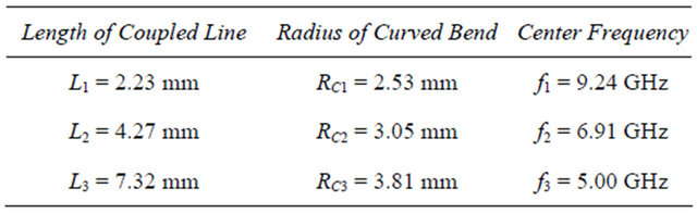
Figure 6 shows that the center frequency can be changed easily. In other words, center frequency is related to the size of the elliptical patch resonator. If the size of the resonator is increased, center frequency shifts to the left. This demonstrates that the design has a high flexibility. Values of the center frequency in Figure 6 are displayed in Table 3.
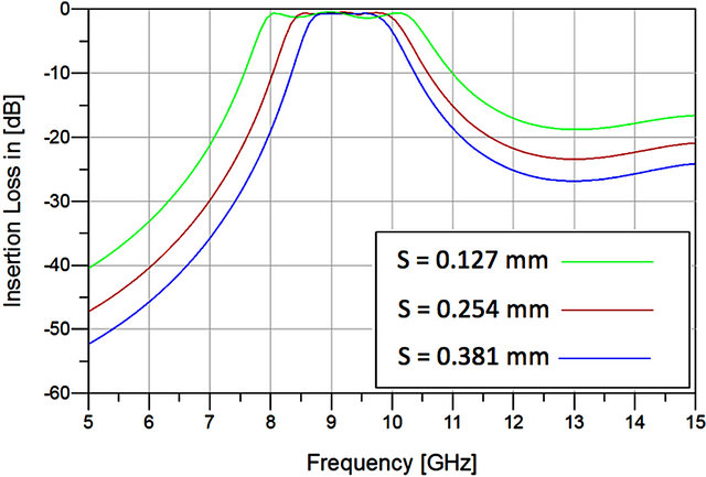
Figure 5. Filter response for different spacing of the coupled lines. Bandwidth of the filter increases as the spacing decreases.
Table 2. Bandwidth and the spacing of coupled lines.
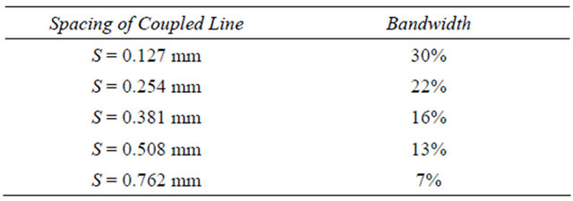
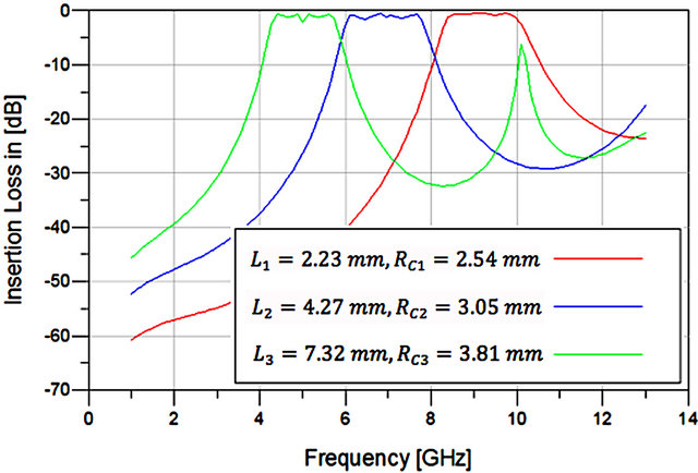
Figure 6. Center frequency shifts to the left as the size of the elliptical patch resonator increases.
Table 3. Center frequency is related to the size of the elliptical patch resonator.
Adding more sections of the elliptical patch resonator can increase the order of the filter. Comparisons between one, two, and three order filters are conducted. As the number of sections increase, the insertion loss of the bandpass filter shows steeper response as shown in Figure 7.
3. Measured Results and Discussion
Following the simulation, the filter configuration was exported from ADS to a Gerber file in order to fabricate using Protomat [12] in the laboratory. A photo of the fabricated filter is shown in Figure 8.
The size of this filter is 2.03λg × 0.734λg, which is very compact, and the λg is the guided wavelength in the transmission line. The guided wavelength depends on the center frequency of the design and the propagating velocity. A vector network analyzer is used to measure the Sparameters of the filter, and a comparison of measurement and simulation results is presented in Figure 9.
As can be seen, the insertion loss (S21) and return loss (S11) measurements provide fairly good agreement with the simulated results. The measured results are shifted by 350 MHz from the simulated results. The differences are believed to be contributed to the board loss at high center frequency, accuracy of the material parameters, and fabrication tools. When the center frequency of the microstrip filter is high, measurements are usually shifted from simulation results because the accuracy of the Protomat is low. The accuracy of the Protomat depends on the size
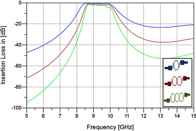
Figure 7. Comparison of different sections of elliptical patch resonators.
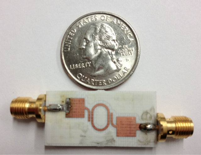
Figure 8. Fabricated elliptical patch resonator bandpass filter.
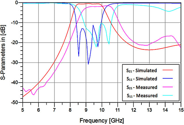
Figure 9. Comparison between measured and simulated results.
of the microstrip filter, which depends on the center frequency. The material parameters are usually slightly different compared with the simulation material parameters, which clearly will affect measurements. The fabrications tools were not small enough because the size of the proposed filter was very compact. In addition, soldering the SMA ports might affect the response of the measurement results. There were difficulties associated with fabricating the filter on a thin RO4003 material, which has a thickness of 0.813 mm.
4. Summary and Conclusion
In this paper, a novel compact bandpass filter was designed, fabricated, and characterized. The filter makes use of an elliptical patch resonator. The proposed filter has an advantage of providing high flexibility in design and tunability in center frequency and bandwidth. The bandwidth can be changed easily by changing only one variable, which is the spacing in the coupled line. The center frequency is tunable by changing the size of the elliptical patch resonator. The insertion loss and return loss of the measurements are in fairly good agreement with the simulation results. The proposed filter can be used for future advanced wireless communication systems.
REFERENCES
- J.-X. Xiao and Y. Li, “Novel Compact Microstrip Square Ring Bandpass Filters,” Journal of Electromagnetic Waves and Applications, Vol. 20, No. 13, 2006, pp. 1817-1826. doi:10.1163/156939306779292156
- G.-L. Wu, W. Mu, X.-W. Dai and Y.-C. Jiao, “Design of Novel Dual-Band Bandpass Filter with Microstrip Meander-Loop Resonator and CSRR DGS,” Progress in Electromagnetics Research, Vol. 78, 2008, pp. 17-24. doi:10.2528/PIER07090301
- M. Nedil, T. A. Denidni, A. Djaiz and H. Boutayeb, “Ultra-Wideband Bandpass Filters Using Multilayer Slot Coupled Transitions,” Journal of Electromagnetic Waves and Applications, Vol. 22, 2008, pp. 501-516. doi:10.1163/156939308784150353
- P. Mondal, M. K. Mandal, A. Chaktabarty and S. Sanyal, “Compact Bandpass Filters with Wide Controllable Fractional Bandwidth,” IEEE Transactions on Microwave Theory and Techniques, Vol. 16, No. 10, 2006, pp. 540- 542.
- Q.-Y. Xiang, Q.-Y. Feng and X.-G. Huang, “A Novel Microstrip Bandstop Filter and Its Application to Reconfigurable Filter,” Journal of Electromagnetic Waves and Applications, Vol. 26, No. 8-9, 2012, pp. 1039-1047. doi:10.1080/09205071.2012.710365
- S. R. Chandler, I. C. Hunter and J. G. Gardiner, “Active Varactor Tunable Bandpass Filter,” IEEE Microwave and Guided Wave Letters, Vol. 3, No. 3, 1993, pp. 70-71. doi:10.1109/75.205668
- M. Sánchez-Renedo, R. Gómez-García, J. I. Alonso and C. Briso-Rodríguez, “Tunable Combline Filter with Continuous Control of Center Frequency and Bandwidth,” IEEE Transactions on Microwave Theory and Techniques, Vol. 53, No. 1, 2005, pp. 191-199. doi:10.1109/TMTT.2004.839309
- B. Liu, F. Wei, H. Zhang, X. Shi and H. Lin, “A Tunable Bandpass Filter with Switchable Bandwidth,” Journal of Electromagnetic Waves and Applications, Vol. 25, No. 2- 3, 2011, pp. 223-232. doi:10.1163/156939311794362704
- S. Ur Rehman, A. F. A. Sheta and M. A. S. Alkanhal, “Compact Mems Based Reconfigurable Bandpass Microstrip Filter Using Defected Ground Structure (DGS),” Journal of Electromagnetic Waves and Applications, Vol. 26, No. 2-3, 2012, pp. 353-365. doi:10.1163/156939312800030785
- D. M. Pozar, “Microwave Engineering,” John Wiley & Sons, Hoboken, 2005.
- http://www.home.agilent.com/en/pc-1297113/advanced-design-system
- http://www.lpkf.com/protmat
NOTES
*Corresponding author.