Int'l J. of Communications, Network and System Sciences
Vol. 5 No. 11 (2012) , Article ID: 24671 , 10 pages DOI:10.4236/ijcns.2012.511078
Improving Inter-Domain Fast Handover Using MIH Services in Mobile WiMAX
Department of Computer Engineering, University of Basrah, Basrah, Iraq
Email: ghaida_alsuhail@yahoo.com, huda.swady@gmail.com
Received August 7, 2012; revised September 12, 2012; accepted September 28, 2012
Keywords: Handover; MIPv6; FMIPv6; Inter-Domain; MIIS; FQDN; Mobile WiMAX
ABSTRACT
Recently, the IP connectivity during the Mobile Node (MN) movement between Base Stations (BSs) belonging to different Internet Service Providers (ISPs) is still a key issue to be tackled. In this paper, therefore, we develop a new scheme to improve the performance of inter-domain fast handover over mobile WiMAX networks. The framework basically relies on the Fast Handover for Mobile IPv6 protocol (FMIPv6) when the Media Independent Information Services (MIIS) as defined in IEEE802.21 standard is applied to enable the Mobile Node in storing the information of the neighboring networks. A Fully Qualified Domain Name (FQDN) is also used to identify the IP address of the previous network operator and the MN during its movements. Since both MIIS and FQDN can support the node mobility between multiple domains, our proposed scheme can also be called P-FMIPv6. The numerical results show that the latency of IP connectivity of this proposed handover can be significantly reduced in addition to less service disruption time during handovers as compared to the existing FMIPv6 when IEEE802.16e network is considered.
1. Introduction
Providing seamless mobility support and maintaining the continuity of the service during the mobile node movement from one location to another is still an important issue for the mobile wireless communications. Mobile IPv6 (MIPv6) protocol [1] has proposed to support mobility in the internet between access networks, but the long handover latency in the MIPv6 degrades the perceived quality of service (QoS) essentially in real time services due to packet disruption and packet loss [2]. Therefore the Internet Engineer Task Force (IETF) has released other main protocol draft called Fast Handover for MobileIPv6 (FMIPv6) [3] which is designed to allow Mobile Node (MN) to anticipate its IP layer mobility by using Link layer triggers. Layer 2 triggers are required for anticipation and initiation handover [4]. They are delivered to the network layer modules as a notification event to report the changes in respect to the link and physical condition [4].
However, many researches have been presented for enhancing FMIPv6 and reducing the handover latency in it. In [5], an improvement to the handover delay is done by using an extension of the router discovery messages to initiate the handover. In [6], fast neighbor discovery and Duplicate Address Detection (DAD) scheme is presented by making each access point execute movement detection by unicast transmission of the stored router advertisement message and implemented a modified neighbor cache to handle configuration of the address under fast DAD. In [7], an enhancement for FMIPv6 handover based on link layer information is presented. One of the major things in FMIPv6 is not supporting global mobility, i.e. it doesn’t support the discovery of the new network IP address when the mobile node moves between multiple domains. Moreover, during the handover initiation time, the MN could lose its connectivity to the Previous Access Router (PAR) due to the sudden disruption of the link. That’s lead MN performs either a normal handover procedure in MIPv6 or the reactive FMIPv6 [8]. This may eventually cause long handover latencies which is not a desirable case. Therefore, in this paper a proposed fast handover scheme P-FMIPv6 is presented to support the MN movement between multiple domains.
The rest of the paper is organized as follows. Section 2 introduces a background about the existing FMIPv6 and Media Independent Handover (MIH) services. Section 3 describes the proposed P-FMIPv6 scheme. Section 4 introduces an analytical model to evaluate the latency performance of the proposed P-FMIPv6 scheme. The results evaluation is presented in Section 5, and finally the conclusions and some recommended future work are drawn in Section 6.
2. Background
In this section, some related works are briefly addressed to support our proposed inter-domain Fast Handover (P-FMIPv6) scheme in this paper.
2.1. The Existing FMIPv6
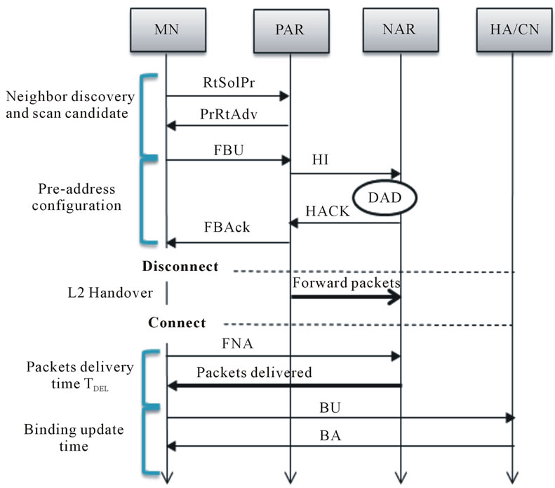
Fast Handover for MIPv6 (FMIPv6) is an extension to MIPv6 for eliminating the handover latency. It depends on the link layer triggers to predict or respond rapidly to the handover events. It introduces a concept of Previous Access Router (PAR) and New Access Router (NAR), this extension allows MN to connect to NAR while still communicating with PAR. In Figure 1(a), once the MN is connected to NAR, it requests PAR to tunnel packets to NAR so that packets are not lost [7,9]. The MN registers its temporary location to its Home Agent (HA) and Correspondent Node (CN) through the Binding Update (BU) procedures. Figure 1(b) illustrates the basic handover procedure of FMIPv6 for intra-domain predictive mode [10]. In this mode, the same internet service provider is considered without the need for MIH services or IP change.
When FMIPv6 is applied to the IEEE802.16e based mobile WiMAX network; the mobile terminal scans to find the available target base stations. The scan results inform the available base station lists and their physical layer information such as strength of signal. The terminal selects one candidate base station and exchanges the router solicitation for proxy (RtSolPr) [3] and proxy router advertisement (PrRtAdv) [3] with current access router. When the terminal receives PrRtAdv message, it may configure its new IP address, referred as care-of address (CoA).
A fast binding update (FBU) [3] will be transmitted when the terminal indicated a handover. Sending of FBU activates the handover initiation (HI) [3] process and waiting fast binding acknowledgement FBAck [3] process. When the target access router receives HI, it confirms the procedure with duplicate address detection (DAD) process [3] and sends HACK message. Packet tunneling then is established, fast neighbor advertisement (FNA) [3] will be sent to inform the target router of the terminal’s existence [3]. The definition of some terminologies used with the fast mobile IPv6 handover process is explained in Table 1.
2.2. Media Independent Handover (MIH)
IEEE 802.21 is a framework that enables seamless handover between networks, which is based on defined protocol stack involved in all the handover devices and provides the interaction among devices for optimizing handover decisions [11]. The MIH introduces a new logical entity called Media-Independent Handover Function (MIHF). The MIHF logically resides between the link layer and the network layer. It is worth mentioning that although the purpose of the working group is to
 (a)
(a) (b)
(b)
Figure 1. Inter-domain handover (a) Network model and (b) FMIPv6 (Predictive mode).
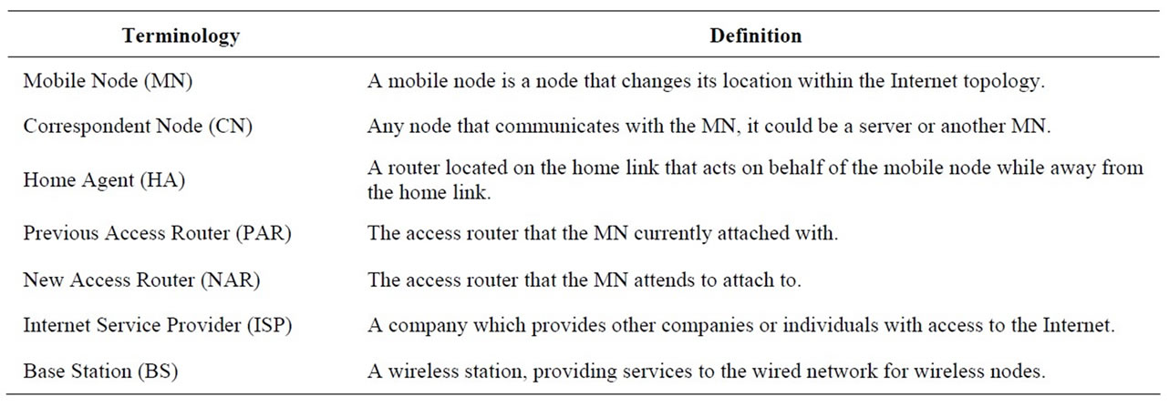
Table 1. The definition of some terminologies for FMIPv6.
support seamless handover between heterogeneous networks; the recommendations can be applied to handover in homogeneous networks [12]. It provides, among others, abstracted services to entities residing at the network layer and above, called MIH Users (MIHUs).
MIHUs are anticipated to make handover and link-selection decisions based on their internal policies, and the information received from the MIHF. So, the primary role of the MIHF is to assist in handovers and handover decision making by providing all necessary information to the network selector or mobility management entities. The latter are responsible for handover decisions regardless of the entity position in the network. Figure 2 represents the 802.21 reference model. Three SAPs are included in the MIH reference model [13]:
• MIH SAP: This interface allows communication between the MIHF layer and the higher layer MIHF users.
• MIH-LINK-SAP: This is the interface between the MIHF layer and the lower layers of the protocol stack.
• MIH-NET-SAP: This interface supports the exchange of information between remote MIHF entities.
In IEEE 802.21, Service access point SAPs with associated primitives between the MIHF and MIHUs (MIH_ SAP) give MIHUs access to the following services that the MIHF provides [11-13]:
1) The Media-Independent Event Service (MIES) provides event reporting about, dynamic changes in link conditions, link status, and link quality. Events can be both local and remote. Remote events are obtained from a peer MIHF entity.
2) The Media-Independent Command Service (MICS) enables MIHUs to manage and control the parameters related to link behaviour and handovers. MICS provides a set of commands for accomplishing that. Commands can be both local and remote. The information obtained with MICS is dynamic.
3) The Media-Independent Information Service (MIIS) allows MIHUs to receive static information about the characteristics and services of the serving network and other available networks in range. This information can be used to assist in making a decision about which handover target to choose and to make preliminary preparations for a handover.
3. The Proposed P-FMIPv6 Handover
The FMIPv6 ensures a low-latency of the handover by anticipating the handover process before the MN loses connection with the current network. As explained in Figure 1, this goal is achieved by utilizing Layer 2 triggers. However, to reduce the overall handover latency in this scheme, we improve FMIPv6 predictive mode handover by developing new inter-domain handover scheme called P-FMIPv6 to reduce the L3 handover latency. In this scheme, MIIS is used to replace router discovery and to retrieve the information required about the current and surrounding networks for making the handover decision process.
3.1. Network Model
We assume the MN is connected with the Serving Base Station (SBS) that belongs to the first domain, where each base station is integrated with exactly one Access Router AR. In this case every change of BS means a change of AR, as shown in Figure 3. The network model and each domain is served by an Information Server (IS) [2]. The IS could be co-located in the AR, and AR has access to the information to assist the handovers.
3.2. The MIH Services Required in P-FMIPv6
The FMIPv6 protocol in the MN is registered for Media Independent Event Service (MIES) notifications (i.e. L2 triggers) within its local stack. This will be done via MIH Event Registration service primitives that work in a request/response mode [6]. The events and commands services that will be registered by the FMIPv6 protocol are present in Tables 2 and 3, respectively. The MIH protocol defines the frame structure for exchanging messages
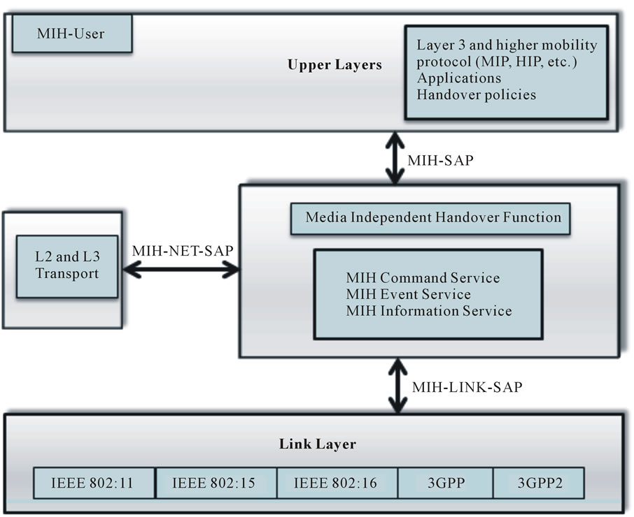
Figure 2. IEEE 802.21 reference model.
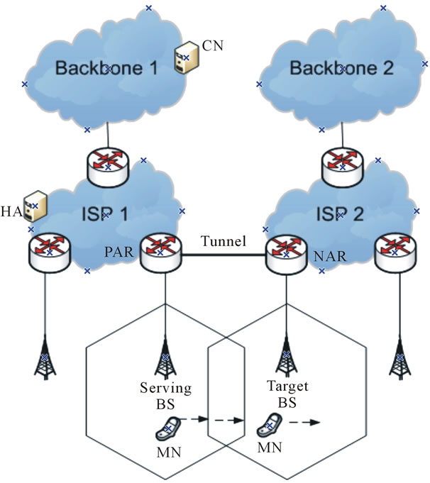
Figure 3. Network model supporting P-FMIPv6 scheme for inter-domain handover.
between MIH function entities. These exchanged information via MIIS are structured in Information Elements (IEs) format coded using specific Type Length Values TLVs [6]. In the proposal subset of IEEE802.21, MIH services are utilized to enhance the handover process in FMIPv6. Tables 2 and 3 list the chosen MIH services and their corresponding primitives and parameters.
3.3. The P-FMIPv6 Procedure
To illustrate the proposed scheme, Figure 4 explains the details of timing signal flow during the handover process between PAR and NAR. In this scenario, the MN moves from the Serving Base Station (SBS) to the Target Base Station (TBS) that belongs to a different IP sub network in different domain. The MN must re-configure a new IP address and re-establish its IP connection. Hence, MN needs to perform the network layer handover besides the L2 handover. More specifically, the P-FMIPv6 solves the addressing problem during the MN movement between multiple domains by providing a mechanism for knowing if the NAR that the MN attends to attach to belongs to the same IP domain or to a different one.
We assume the existing of the information server in each domain in order to provide the router with the information of the domain. The IS could be thought of as the network knowledge reservoir which can be used to provide essential network related information, e.g., list of network providers, PoA MAC address, channel information, higher layer services etc., which may allow for enhanced network selection. In our network model the IS is a network entity which serves as a MIH Point of Service (PoS) but is located deeper in the access network.
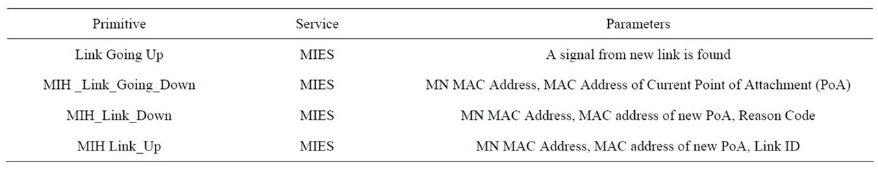
Table 2. The MIH service primitives.
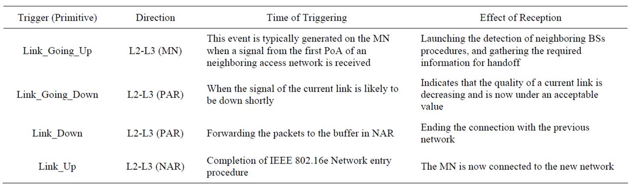
Table 3. The description of MIH services for P-FMIPv6.
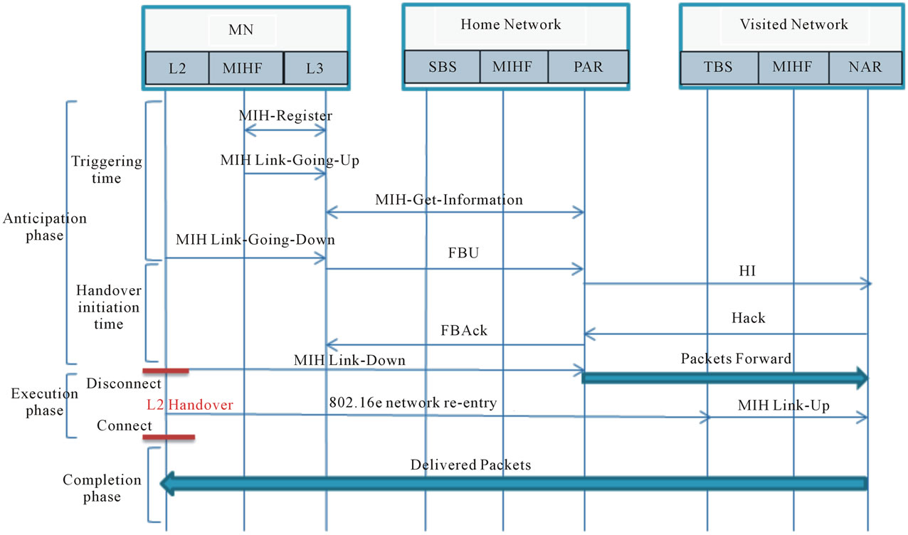
Figure 4. The proposed P-FMIPv6 signaling flow.
These servers need to be discovered, [14] describes the mechanism to discover the location of the IS via layer 3. In addition we will propose existing additional IE is the new network prefix IE transporting through the MIH messages to help in pre-configuration of the new IP address as explained in Figure 4.
To achieve a more clarity in describing the details of this proposed P-FMIPv6, the handover process is divided into three phases as follows. The first phase is called the anticipation phase; in which the MN anticipates its next (upcoming) connection before the disconnection with its current link. The second phase is the execution phase which through the MN performs L2 handover and finally the third phase is the completion phase, in which the MN completes its the handover process by delivering the buffered packets from the NAR to the MN.
The description of each phase is illustrated as follows:
1) Anticipation Phase: This phase is divided also into two interval processes: the triggering time (TT) part and the handover initiation time (HIT) part described as follows.
At the beginning of the triggering time (TT) process the MN registers for Media Independent Event Services MIES notifications (L2 triggers). And when the MN senses an increase in the signal strength of one of the neighboring network’s BS, it will trigger MIH Link_ Going_Up event to the IP layer. Once the MN receives this trigger it will start its operation of scanning, detecting the candidates BS’s of the neighboring network and gathering the important information that helps in the handover process. The required and necessary information is transporting through MIH messages (MIH Get_ Information_Request/MIH Get_Information Response) messages. The MN will retain this information stored in its neighboring binding cache, and the information is such as (lower layer information, L3 information of the neighboring access network).
Here, if the new network prefix IE between these Information Elements (IEs) is stored in the cache memory of the MN, the MN can pre-configure a new IP address automatically using the new network prefix and MN link Interface Identifier ID. The MN in this case will be provided with a pre-MN prefix to configure its address which will be a new IP address. By using this addressing, there will be no need to apply DAD procedure. Hence, the handover latency will be reduced and the chance of handover procedure to run in the Predictive Mode is largely increased since little or no time spent processing DAD. As a result, this procedure can support a much higher mobility speed [15].
After completing the triggering time (TT) process, the MIH Link_Going_Down (LGD) will be triggered to the IP layer as an indication for sending the FBU message and starting the handover initiation time (HIT). The LGD trigger is issued from MIH to IP layer in PAR and we specify this event as the start of handoff initiation phase. The FBU message with the new configured IP address is sent to the PAR. The previous IP address can be obtained by using the FQDN. This address configuration will be done early during the anticipation phase before occurring L2 handover and that will reduce the usual taken time for address configuration during the L3 handover procedure of FMIPv6. A Tunnel between the two ARs is established by exchanging HI/HAck messages between them and sending the FBAck message to the MN to validate the use of the new address as the new network IP address.
2) Execution Phase: When the MN receives the FBAck message from the PAR, its MAC layer triggers the MIH Link_Down event to the IP layer referring to the start of the Execution phase. The disruption with the previous link occurs in this phase. The packet forwarding to NAR starts right after the MIH Link_Down event. These packets are buffered in the NAR until the MN reaches in the new network. MIH Link_Down event is an indication to the disconnection with the old network and executing L2 handover, the L2 handover and the IEEE 802.16e network re-entry procedure is performed. Immediately after completing the network re-entry between MN and TBS, the TBS MAC layer triggers MIH Link_ Up event to the IP layer. This Link-Up event will replace the need for FNA message.
3) Completion Phase: In this phase the handover processes are completed by releasing the buffered packets from the NAR and delivers them to the MN without loss. Subsequently, the MN performs the registration with HA by sending and receiving a BU and a BA messages. The MN confirms the registration and removes the FMIPv6 tunnel.
As a result, Figure 5 can illustrate the flow chart of the P-FMIPv6 scheme; it describes the entire proposed handover scheme as follows:
a) The actual handoff procedure starts as soon as MIH Link_Going_Up event is arisen, so the MN will wait the arising of this event to start and perform the other procedures of the handover.
b) The MN exchanges MIH information messages to obtain the necessary information required for the handover process.
c) When the signal strength of the ongoing link is degraded, The MIH Link_Going_Down is triggered in response to this degradation of the current BS’s signal strength.
d) The FBU will be provided with the pre-MN prefix, comparing the new network prefix with the previous one which can be obtained by using the FQDN of the previous network, if the new network prefix was different that means the NAR occurs in a different domain (different ISP) and that leads to the necessity of configuring a new IP address by combining the new prefix and the link interface identifier, and this case represents the scenario of the proposed P-FMIPv6 scheme, on the other hand if the two prefixes were the same that means the two AR’s occur in the same domain and the comparison will depend on the subnet prefix, if it was different the MN will need to configure anew care of address instead of a new IP address to support its movement.
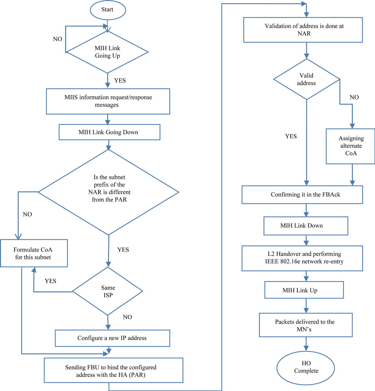
Figure 5. Flow chart of the P-FMIPv6 scheme.
e) Sending the FBU message to bind the configured address with its home agent (PAR). To establish the tunnel between the two AR’s, PAR sends HI message to NAR in order to validate the new configured address and activate the tunnel between the two AR’s, in response to this message NAR sends back HAck message to PAR to confirm this address validation, in case of the address was invalid a new alternate address will be assigned with the HAck message. Then PAR sends FBAck for address confirmation.
f) As soon as the FBAck message is received by the MN, tunneling the packets is being activated and forwarding the packets is starting from the current care of address to the new configured IP address of the new domain. Triggering MIH Link Down event is important for executing the handover properly.
g) The MN connection will be disrupted during L2 handover, and the IEEE802.16e network re-entry is performed. Later the Link_Up event is triggered from the MAC layer of NAR to the IP layer to advertise the connection with the new network, thus this event will replace FNA message. So there is no need to use this message any more.
h) Finally, the buffered packets are delivered to the MN indicating to the end and completing of the handover process.
4. Analytical Model
In this section, the analysis based on message triggers is done for examining the performance of the inter-domain P-FMIPv6 scheme to assess the total handover latency. Generally, the handover latency is defined as the time interval between last reception of data on the current Care of Address (CoA) and the moment when MN starts receiving packets at the new point of attachment [8,16]. Thus the handover latency can be evaluated by the sum of all particular delay intervals of L2 and L3 in the protocol stack where the mobile node experiences during the FMIPv6 and P-FMIPv6 handovers. In P-FMIPv6, it is found that the handover process of the wireless link layer (L2) has no a significant impact on the L3 handover process. Therefore, the delay caused by L2 mechanism can be discarded in this case because it does not have any impact on L3 handover mechanism. For this reason, L2 handover time interval will not be further examined and will be considered as a constant for P-FMIPv6 scheme.
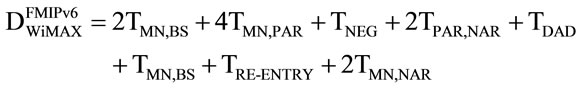
To evaluate the total handover time of our P-FMIPv6 scheme, the typical network parameters defined in Table 4 are required. It is clearly noticed that there exist various types of delays introduced due to the handover process in L2 and L3. In FMIPv6 scheme, the total handover time consists of the combination of the of transmission time between the MN and BS (TMN,BS) during the scanning phase, the transmission time between the MN and AR during the transmission of Router Solicitation and Advertisement messages RtSolPr & PrRtAdv respectively and also the Binding messages (4TMN,PAR). TNEG indicates the negotiation time between the MN and BS. TPAR,NAR is the time required for establishing a tunnel between PAR and NAR, TREENTRY represent the time required for the re-entry phase of layer 2 handover and the time between MN and NAR for Fast Neighbor Advertisement (FNA) and forwarding packets messages (2TMN,NAR).
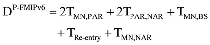
In P-FMIPv6 handover, we can simply derive a delay formula which consists of different delay intervals caused by the binding messages between the MN and PAR (2TMN,PAR), the delay occurred due to establishing the tunnel between the PAR and NAR (TPAR,NAR), plus the re-entry time (TRe-entry), and finally the time required to perform forwarding the packets from the NAR to MN(TMN,NAR). As a result, the total handover time for both handover schemes of RFC-5270 and the proposed scheme P-FMIPv6 are expressed as

Table 4. The numerical parameters.
 (1)
(1)
 (2)
(2)
In addition, the service disruption time (SDT) of FMIPv6 and P-FMIPv6 can also be defined by Equations (3) and (4) respectively
 (3)
(3)
 (4)
(4)
The service disruption time is known as the period of time when the MN cannot maintain active connection with the current BS to send and receive any data packets. In our proposed P-FMIPv6 the FNA is omitted by making use of MIES and thereby reducing the SDT which is an important parameter for assuring good QoS for realtime applications.
5. Performance Evaluation
To evaluate the P-FMIP protocol, the typical values of network parameters are defined in Table 4. Many research studies like [10,16-19] have basically used them under different handover procedures. By applying such numerical values in Equations (1)-(4), the following results are obtained as follows:
Figure 6 shows the handover latency of the P-FMIPv6 and the predictive RFC-5270 schemes. In P-FMIPv6, it is clearly shown that the proposed mechanism can remove the delay occurred by router discovery messages (RtSolPr and PrRtAdv) and FNA message, from the handover latency. We can also observe that due to the proposed P-FMIPv6 the handover latency will be reduced significantly by comparing it with the existing FMIPv6 scheme over 802.16e network [13]. The improvement in the handover latency roughly achieves 70% which is a very noticeable percentage value.
On the other hand, Figure 7 compares the service disruption time between the predictive FMIPv6 and the proposed P-FMIPv6 scheme. We assume the time for L2 handover (TL2) is 50 ms and the time delay of FNA message TFNA is 20 ms, and the delivery time delay (TDEL) is about 40 ms. In the case of the proposed P-FMIPv6, it is found that we can obtain better performance than the original scheme.
In summary, the results show clearly that our proposed scheme features much shorter than the total handover delay and SDT as well compared to the original FMIPv6. Therefore, we can conclude that P-FMIPv6 can significantly improve the delay performance of Fast handover of MIPv6 for real time applications during the handover process.
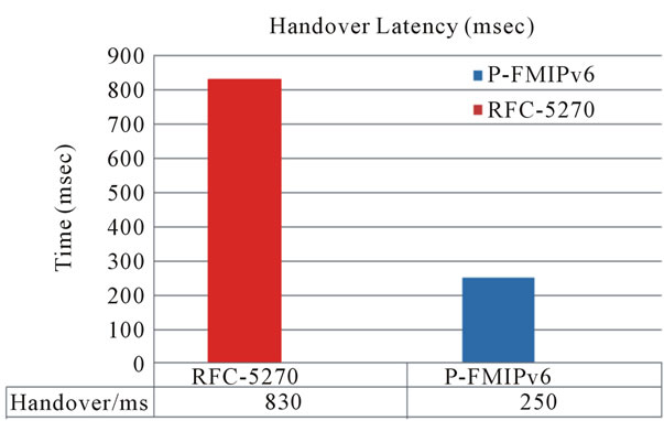
Figure 6. Handover latency of P-FMIPv6 vs RFC-5270.
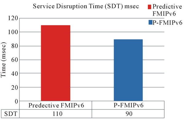
Figure 7. Service disruption time of P-FMIPv6 vs predictive FMIP.
6. Conclusion
In this paper, an inter-domain Proposed Fast Handover Scheme P-FMIPv6 is presented. The proposed scheme is based on MIIS information function and MIES, and the MN can perform the handover operation without the need for router discovery messages and FNA message. The analytical model of this P-FMIPv6 can introduce a significant reduction in the handover latency and a reasonable handover disruption time. The future work will be on examining the proposed P-FMIPv6 on intra-domain handover analysis and taking the cost evaluation in the consideration besides the delay of the handover process.
REFERENCES
- D. Johnson, et al., “Mobility Support in IPv6,” RFC 3775, IETF, 2004.
- Y. Y. An, B. H. Yae, K. W. Lee, Y. Z. Cho and W. Y. Jung, “Reduction of Handover Latency Using MIH Services in MIPv6,” Proceeding of AINA, Vienna, 18-20 April 2006.
- R. Koodli, et al., “Fast Handovers for Mobile IPv6,” RFC 4608, IETF, 2006.
- N. Montavont and T. Noel, “Handover Management for Mobile Nodes in IPv6 Networks,” IEEE Communications Magazine, Vol. 40, No. 8, 2002, pp. 38-43. doi:10.1109/MCOM.2002.1024413
- M. Alnas, I. Awan and R. D. W. Holton, “Performance Evaluation of Fast Handover in Mobile IPv6 Based on Link-Layer Information,” Journal of Systems and Software, Vol. 83, No. 10, 2010, pp. 1644-1650. doi:10.1016/j.jss.2010.03.080
- C. Wu and P. Wang, “Improved Fast Handover Scheme for Hierarchical Mobile IPv6,” 4th International Conference on Computer Science and Education, Wuhan, 25-28 July 2009.
- B. Park, S. Lee and H. Latchman, “Performance Analysis of Enhanced-Mobile IPv6 with Fast Handover over Endto-End TCP,” IEEE Communications Society Subject Matter Experts for Publication in the WCNC 2006 Proceedings, Las Vegas, 3-6 April 2006.
- H. J. Jang, J. Jee, Y. H. Han, S. D. Park and J. Cha, “Mobile IPv6 Fast Handovers over IEEE 802.16e Networks,” RFC 5270, IETF, 2008.
- C.-H. Shih and Y.-C. Chen, “A FMIPv6 Based Handover Scheme for Real-Time Applications in Mobile WiMAX,” Journal of Networks, Vol. 5, No. 8, 2010, pp. 929-936. doi:10.4304/jnw.5.8.929-936
- L.-L. Mo, “Research on Mobile IPv6 Technology and Handover Performance Optimization,” American Journal of Engineering and Technology Research, Vol. 11, No. 9, 2011, pp. 941-946.
- J.-H. Seol and J.-M. Chung, “IEEE 802.21 MIH Based Handover for Next Generation Mobile Communication System,” 4th IEEE International Conference on Innovations in Information Technology, Dubai, 18-20 November 2007, pp. 431-435.
- V. Gupta, “IEEE802.21 Standard and Metropolitan Area Networks: Media Independent Handover Services,” Draft P802.21/D00.05., 2006.
- M. Ali, P. Pillai, Y. F. Hu and K. Xu, “Load-Aware Radio Access Selection Heterogeneous Terrestrial Wireless Networks,” International Journal of Computer Networks & Communications, Vol. 3, No. 6, 2011, p. 95. doi:10.5121/ijcnc.2011.3606
- T. Melia, G. Bajko, S. Das, N. Golmie and J. C. Zuniga, “IEEE 802.21 Mobility Services Framework Deign (MSFD),” IETF Draft, RFC 5677, 2009.
- P.-Q. Huynh, P. Jangyodusk and M. Moh, “Supporting Video Streaming over WiMAX Networks by Enhanced FMIPv6-Based Handover,” Proceedings of the 4th International Conference on Information Systems, Technology and Management, Bangkok, 10-12 March 2010.
- Q. B. Mussabbir, W. Yao, Z. Niu and X. Fu, “Optimized FMIPv6 Using IEEE802.21 MIH Services in Vehicular Networks,” IEEE Transactions on Vehicular Technology, Vol. 56, No. 6, 2007, pp. 3397-3407. doi:10.1109/TVT.2007.906987
- M. Skořepa and R. Klügl, “Analytical Method for L3 Handover Latency Evaluation,” Advances in Communications, Computers, Systems, Circuits and Devices, World Scientific and Engineering Academy and Society Stevens Point, Wisconsin, 2010, pp. 342-347.
- C. Makaya and S. Pierre, “An Analytical Framework for Performance Evaluation of IPv6-Based Mobility Management Protocols,” IEEE Transactions on Wireless Communications, Vol. 7, No. 3, 2008, pp. 972-983. doi:10.1109/TWC.2008.060725
- M. Skorepal and R. Klugl, “Analytical Comparison of Mobile IPv6 Handover Schemes,” Elektrorevue, Vol. 2, No. 2, 2011, pp. 22-26.