Int'l J. of Communications, Network and System Sciences
Vol.2 No.4(2009), Article ID:540,10 pages DOI:10.4236/ijcns.2009.24031
Optimal Positions of Relay Stations for Cluster-BasedTwo-Hop Cellular Network
1Performance Engineering Laboratory (PEL), School of Electronic Engineering, Dublin City University, Ireland
2Next Generation Wireless Systems, Dhirubhai Ambani Institute of Information and Communication Technology (DAIICT), Gandhinagar, India
Email: hrishikesh@ieee.org
Received December 22, 2008; revised February 27, 2009; accepted April 1, 2009
Keywords: Cluster-Based Design, Power Control, Relay Stations, Two-Hop Cellular
ABSTRACT
Multihop cellular networks is an exciting and a fledgling area of wireless communication which offers huge potential in terms of coverage enhancement, data-rates, power reduction, and various other quality of service improvements. However, resource allocation in MCN is an NP-hard problem. Hence, significant research needs to be done in this field in order to efficiently design the radio network. In this paper, optimal position of relay stations in a hierarchical cluster-based two-hop cellular network is investigated. Vector algebra has been used to derive general equation for carrier-to-interference ratio (C/I) of a mobile station. It has been observed that when the transmit power of base station (BS) and the gateway (GTW)/relay station (RS) are same, the RSs should be located close to mid-point of BS and the edge of the cell. However, significantly, when the transmit power of the BS is greater than that of the GTW, then the RSs should be placed closer to the edge of the cell, in order to maximize the minimum C/I at any point in the cell. This in turn results in higher modulation technique at the physical layer, and hence, a higher data-rate to all the users in the system.
1. Introduction
The next generation cellular networks need to provide very high data-rates to the end users in order to support the ever growing demand of high quality multimedia services while on the move. An increase in the data-rate is possible either by increasing the bandwidth or reducing the interference. The data-rate can also be increased by increasing the transmit power or by reducing the distance between the source and destination node. Since mobile stations (MSs) are energy constrained devices, the transmit power of the MSs cannot be increased indiscriminately, and hence, traditional single-hop cellular networks cannot provide high data-rate communication. Importantly, a high quality of service (QoS) cannot be provided to the wireless devices due to the large transmission distance between the base station (BS) and MSs. Reducing the cell coverage area by increasing the number of BSs is not a feasible solution due to the enormous cost of installing a BS. An efficient alternate solution to increase the data-rate is to employ relay stations (RSs), alternatively known as gateways (GTWs), whereby, the BSs would communicate with the far off and otherwise unreachable MSs in multiple hops through GTWs [1]. Figure 1 shows a single cell scenario for next generation multihop cellular networks (MCN). Combining cellular and multihop communication models in a wireless network results in better relaying and avoids traffic congestion [2]. It is shown in [3] that connectivity of the network is increased drastically in an infrastructure-based multihop network as compared to a traditional single-hop cellular or a distributed ad hoc network. Usage of relays can clearly help in improving the performance of the users especially at the edge of the cells, and thereby solves the coverage problems for high data-rates in macrocells [4].
A relay based multihop hybrid cellular network was proposed in [5] in order to balance the traffic load among highly loaded cells and lightly loaded cells. Several architectures and mechanisms have been proposed in the recent past [6,7] in order to efficiently design a MCN. In addition, a time division duplexing (TDD)-based MCN offers the potential to integrate various overlapping wireless technologies such as UMTS or CDMA 2000 (3G networks), WiMAX and WiFi [8]. Hence, by having simultaneous transmission by both BSs and relays, capacity gains can also be achieved in the cellular network. At the same time, integrating multihop component into cellular networks requires additional radio resources and increased overhead signals to transmit data in different hops and that too over a heterogeneous network [9]. In addition, interference is created due to a larger number of simultaneous transmissions in the network. Hence, the actual benefit of multihop relaying becomes unclear [10]. In fact, it is shown in [9,11] that if the MSs are close to the BS, then relaying and multihop need not be always beneficial. Hence, an efficient and an adaptive resource allocation scheme is needed in order to maximize the system capacity. However, resource allocation is a very challenging issue and is proved to be an NP-hard problem [12]. Hence, researchers across the world have mainly focused on two-hop cellular networks. Several algorithms have been recently proposed for two-hop cellular networks [13–15]. Though effective, these algorithms only provide a marginal benefit. Recently, a novel hierarchical cluster-based architecture for two-hop cellular network has been proposed in [16,17]. The cluster-based design is found to be superior in terms of the attainable system capacity than the benchmark algorithms available in the literature [17]. In this architecture,
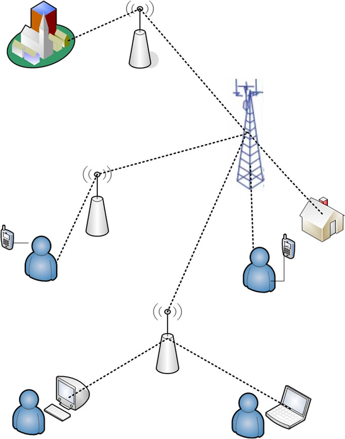
Figure 1. Example of a multihop cellular network.
the cells are divided into two regions, the inner and outer region. The MSs in the inner region communicate with the BS directly, like in a traditional single-hop cellular network. Significantly, the MSs in the outer region are grouped into several clusters, and these MSs communicate with the BS in two hops through the cluster-head nodes, which act as RSs/GTWs.
In this paper, the optimum position of the GTWs in the cluster-based architecture is investigated for different transmit power ratios between the BS and GTW. An uncoded system is considered in the baseband design, and a minimum uncoded bit error rate (BER) of 10−2 is taken as the prerequisite for any link to communicate (an equivalent BER of approximately 10−6 in a coded system). A carrier to interference ratio (C/I) threshold is defined according to the BER so that the C/I at any position in the cell does not fall below the threshold. Vector algebra is used to compute the optimum GTW position in the cell that would minimize the transmit power required at both the BS and the GTW.
The organization of the paper is as follows: Section 2 describes the hierarchical cluster-based two-hop cellular architecture. Section 3 provides a mathematical analysis for calculating the C/I at any position in the outer region of the cell, and also derives the relation between the GTW position, and the transmit power ratio between the BS and the GTW node. Section 4 explains the numerical results and its implication, and finally, conclusions are provided in Section 5.
2. System Model
A multi-cellular network is considered with a center cell surrounded by six cells in the 1st tier. Each cell has a BS at the center, and has an edge of length, r. Each cell is divided into two regions: an inner region and an outer region. The inner region is a circle and has a radius, τr, where 0 ≤ τ ≤ 1. The MSs in the inner region communicate with the BS directly. The outer region is divided into several elliptical sectors, also called as clusters. It has been shown mathematically in [18] that a maximum system capacity is achieved when the number of clusters in a cell is six. Hence, in the cluster-based design, the MSs in the outer region are clubbed into six clusters per cell, as shown in Figure 2. Each MS in any of the clusters communicates with the BS in two hops, through the GTWs, that act as cluster-heads. A time division multiple access (TDMA) scheme is considered so that the relays can receive and transmit the signal at the same frequency. Being a two-hop network, the MSs in the outer region require two different radio resources (two time instants in a TDMA system) to communicate to the BS. Hence, every pair of the two-hop network would communicate over only half the TS period, as compared to an equiva

Figure 2. Multi-cellular architecture with all GTWs in cell located at equidistant distance from the BS.
lent single-hop network. Since the transmission distance of every communicating pair is reduced in the cluster-based two-hop design, as compared to a single-hop network, the same radio resource could be potentially reused twice in every cell, and also in every adjacent cell in the seven-cell scenario. Thereby, a frequency reuse ratio of one is achieved. However, this also results in an increase in the interference across every communicating receiver. A Protocol Model is considered in the system design in order to reduce the interference [19]. As per this model, if dc is the transmission distance between a transmitter and receiver, then a circular region of radius (1 + ∆)dc is defined around every communicating receiver so that, within this region, there is no other transmitter apart from the desired transmitter. The term, ∆, is known as the spatial protection margin, or as the exclusion range ratio. It should be noted that increasing ∆ decreases the interference that the receiver might experience, but at the same time, it also decreases the number of pairs in the network that can communicate using the same radio resource [20].
It has been shown in [21] that in order to optimally trade-off between the amount of interference experienced by each user and the number of simultaneously communicating users, the value of ∆ should be close to unity. Hence, a ∆ of 1.0 is considered in the hierarchical cluster-based two-hop cellular design. In Figure 2, the BS →GTW1 pair communicates simultaneously with the GTW2 → MS pair that is located diametrically opposite with respect to the BS. A perfect synchronization is thereby maintained in the cluster-based design with regard to the selection of concurrent communicating pairs within the cell. Two sets of concurrently communicating pairs are shown in Figure 2(d) and Figure 2(e). In case of downlink transmission, for example, the transmission distance of BS → GTW communicating pair is r/2, and the interfering transmitter GTW is located at a distance of r from the intended receiver. Similarly, the transmission distance of GTW → MS in the outer layer is less than or equal to r/2. Irrespective of the transmission distance of GTW → MS pair, the desired receiver in this case (MSs located in the outer layer) is at least twice the distance from the interfering transmitter (BS in this case). Hence, it can be observed that the intended receiver is separated from all the interfering transmitters by a minimum distance of twice the transmission distance, i.e., ∆ = 1.0. In the next section, a general equation for C/I of the MS at any position in the outer layer of center cell is derived. During the complete analysis carried out in this paper, the center cell in the seven-cell scenario is the cell of interest (CoI).
3. Mathematical Analysis
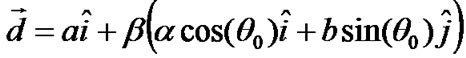
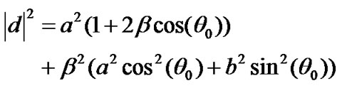
The CoI is surrounded by six cells in the 1st tier. In each of the six cells, there is a BS at the center, given by BS1, BS2, ..., BS6. A constant traffic pattern between uplink and downlink is considered in both the CoI and also in all the adjacent cells (it could be symmetric or an asymmetric traffic). For the mathematical analysis, a downlink communication is being considered. Hence, as per the cluster-based design, the BS in each adjacent cell would communicate with a GTW node, and at the same time, another GTW node located diametrically opposite to the receiver GTW node would communicate with the MS in its cluster. Let the transmitting GTWs in the adjacent cells be GTWTX1, GTWTX2,..., GTWTX6. In the clusterbased design, each cluster is represented by an ellipse, as shown in Figure 2(a). Also, as can be seen from Figure 2(a), there is a small area between two elliptical clusters. The MSs in these areas are assigned to one of the clusters, and hence, these MSs would communicate with the BS through the corresponding cluster-head GTWs. However, in order to simplify the mathematical analysis, the cluster is still approximated by an ellipse. As can be seen from Figure 3, every point in the cluster region is given by the vector: β(a cos(θ0) î + b sin(θ0)ĵ), where 0 ≤ θ0 ≤ 2π is the angle measured from the center of the ellipse to the position of the MS. By varying the value of β from 0 to 1, the whole area of the ellipse is spanned, with b and a being the semi-major axis and semi-minor axis of the ellipse, respectively.
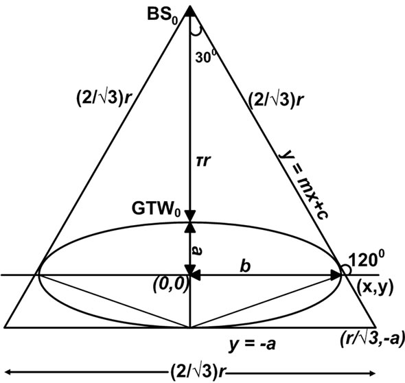
Figure 3. One sector of a hexagonal cell.
3.1. Calculation of a & b
Consider a sector of the cell as shown in Figure 3. For the ease of mathematical analysis, the two edges of the sector are expanded to form an equilateral triangle. Hence, the edge length of the equilateral triangle is 2r/√3. The height of the triangle is of length, r. The radius of the inner layer circle is τr. As the value of τ changes, the value of ‘a’ and ‘b’ also changes. The center of the ellipse (in the desired cluster in CoI) is taken as the origin. Figure 3 shows the elliptical cluster and the distance of the BS from the reference point. The radius of the inner region and the edge of the cell are related by the semiminor axis of the ellipse by the expression: τr +2a = r. Therefore, a = r/2 (1 − τ). From Figure 3, it can be figured out that the slope of the tangent to the ellipse is −√3. Hence, by equating the tangent slope of the ellipse to −√3, we get:
 (1)
(1)
Substituting for x in the above equation, we get:
 (2)
(2)
and
 (3)
(3)
Substituting x, y and m in the tangent equation, y = mx + c, the value for c is obtained as:
c2 = a2 + 3b2. Also, (r/√3, −a) passes through the tangent equation. Therefore, substituting it, one gets:
 (4)
(4)
3.2. Calculation of GTW Power with Respect to BS Power
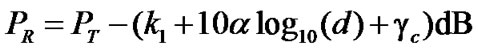
For a transceiver pair separated by a distance, d and transmit power, PT the receiver power is given by [22]:
 (5)
(5)
where k1 is the propagation constant, α is the pathloss exponent and γc is the shadowing factor. In case of a cluster-based two-hop cellular network, the transmission distance is small, and hence, shadowing is much less than compared to an equivalent single-hop network. Hence, the shadowing factor is taken as γc = 0, in the mathematical analysis in this paper. However, the effect of shadowing is considered in the simulations, as can be observed in Section 4.
The minimum receiver sensitivity (minimum carrier power) for any MS in the cell in order to correctly decode the data is taken as X dB (i.e., x Watts). Hence, the farthest point both in the inner region and in the outer region should have this sensitivity level. In the inner region, the farthest point is at a distance τr from BS. Therefore,
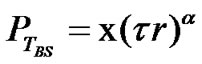 (6)
(6)
In the outer region, the farthest point from the cluster-head GTW is at θo = π/3. Therefore, the distance of farthest point in the outer region from GW, dmax is given by
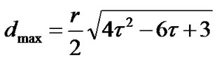 (7)
(7)
Therefore,
 (8)
(8)
and the transmit power ratio between BS and GTW is given by:
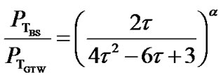 (9)
(9)
3.3. Calculation of Position Vector for All Transmitters
The position vector of an MS from its cluster-head GTW1 is given by:
 (10)
(10)
On similar lines, the position vector of the MS from its own BS is given by,
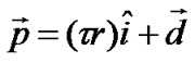 (11)
(11)
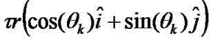
The position vector of the BSs in the adjacent cells, with respect to the BS in the central cell, is given by:
 (12)
(12)
where

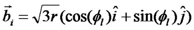
and l is an integer which varies from 1 to 6. Similarly, if θ1, ..., θ6 are the angles measured between the BS1, BS2, ..., BS6 and the transmitting GTWs of the adjacent cells, GTWTX1, GTWTX2, ..., GTWTX6, then the position vectors of these gateways from their corresponding BSs would be given by:
 =
= (13)
(13)
where 0 ≤ θk ≤ 2π and k is an integer which varies from 1 to 6.
3.4. Calculation of C/I
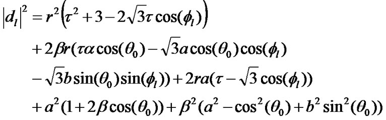
The MS in the center cell (CoI) would experience intracell interference from its own BS, BS0. In addition, it would experience significant interference from all simultaneous transmitters from the 1st tier of cells. As shown in Figure 4, the MS would experience inter-cell interference from BS1, ..., BS6 and GTW1, ..., GTW6. Let the interference powers of these twelve inter-cell interferers be denoted by PI1, ..., PI12. Similarly, let d0 be the distance of the intended receiver from the intra-cell interferer and d1, d2, ..., d12 be the distances between the MS and BS1, ..., BS6, GTW1, ..., GTW6. Hence, the distance of the intra-cell interferer (BS0) and the twelve inter-cell interferers would be given by:
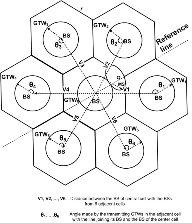
Figure 4. 7-cell scenario for location of transmitting BSs and GTWs.

where l and k are integers which vary from 1 to 6. The distance of the interfering transmitters from the desired receiver, d0, dl and dk+6 are given as:
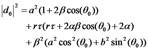 (14)
(14)
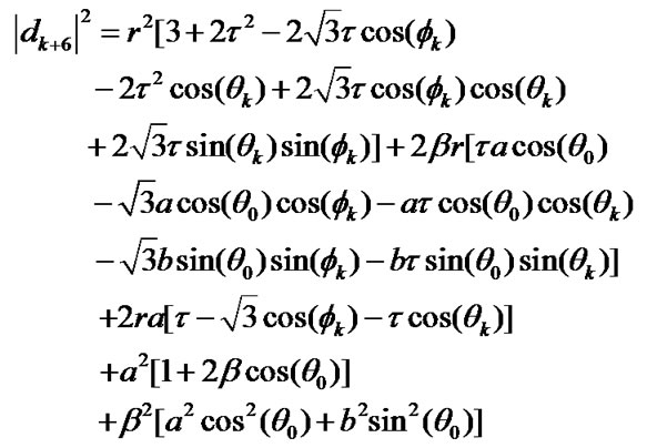 (16)
(16)
Therefore, using the above distance magnitudes, the interference power received at the MS is given by the following equations:
The power from the intra-cell interferer is:
 (17)
(17)
The power received from the interfering BS transmitters, PI1, ..., PI6 are given by:
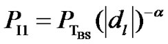 (18)
(18)
Similarly, the received power, PI7, ..., PI12 from the interfering GTWs of the adjacent cells are given by:
 (19)
(19)
If C is the carrier power of the desired transmitter, then:

where
 (20)
(20)
The C/I experienced at the MS in the outer layer is therefore given by:
 (21)
(21)
4. Performance Evaluation
A seven-cell scenario with a center cell and six cells in the 1st tier is considered in the system design. The edge length of each of the hexagonal cells is taken as 1 km. The BS is located at the center of the cell. All the GTWs are equidistant from the BS and also equidistant from each other. However, the exact location of the GTWs with respect to the BS would vary with τ. A downlink transmission scenario is considered in the analysis. Hence, in the cluster-based design, the BS and the GTWs in the adjacent cells would be the interfering transmitters for the receivers in the CoI. The MSs in the center cell are distributed uniformly. However, the position of the MS in the outer layer of CoI does not play any significant role in our analysis. This is because; the main focus of the analysis is in determining the exact location in the CoI where the C/I would be minimum and how this minimum C/I could be maximized by varying the GTW position and the transmitter power. The equations derived in Section 3 in the mathematical analysis are used to calculate C/I for all possible positions of GTW nodes in all the six adjacent cells. The position of the transmitting GTW in each adjacent cell is varied across 360 degrees with every 1 degree variation. This results in huge number of possible combinations (3606 = 2.1768e15). Hence, the computations were done using Matlab. It should however be noted that these are not simulation results but theoretical results obtained from the different position of GTWs in the adjacent cells in the cluster-based two-hop design. In order to assess the performance of varying the location of τ, the value of τ is varied from 0.1 to 1 in steps of 0.01. The performance is evaluated for different values of path-loss exponent, α.
For high data-rate transmissions in B3G (beyond 3G) and 4G networks, a coded BER of 10−6 to 10−7 is required. In a corresponding uncoded network design, as in our system, a BER of 10−2 would however be sufficient [22]. When a combination of convolutional coding and Reed Solomon coding techniques is considered, a BER of 10-2 would translate into a BER of 10−6 or beyond, in a coded system. Table 1 shows the minimum required C/I for different modulation schemes for an uncoded system at a BER of 10−2. The higher the modulation technique, the higher is the achievable link data-rate. Hence, in this paper, the optimum GTW positions are analyzed for different C/I values. A minimum C/I of 4.6 dB is required at the receiver of a communicating pair in order to transmit
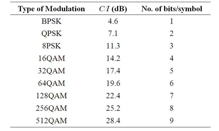
Table 1. Minimum required C/I for different modulation schemes for an uncoded system with a BER of 10-2.
signal using BPSK modulation technique. Similarly, a minimum C/I of 7.1 dB is required for data transmission using QPSK modulation technique. Hence, if the received C/I is between 4.6 dB and 7.1 dB, only BPSK scheme could be used. Table 2 shows the minimum transmit power required at the GTW and at the BS for different power ratios, for three different C/I values: 4.6 dB, 6 dB and 7.1 dB. It can be observed that in order to achieve a minimum C/I of 4.6 dB at any point in the cell, if the BS and the GTW transmit powers are same, then both BS and GTW should transmit with a minimum power of 0.47 W. Also, for this point, all the GTWs in the cell should be located at a distance of 0.48r from the BS. The transmit power of the GTW can be reduced by increasing the BS to GTW transmit power ratio. When the transmit power ratio between the BS and GTW is 2:1, the minimum transmit power of the GTW reduces to 0.441 W. Similarly, if the transmit power ratio is further increased to 4:1, then the minimum transmit power at the GTW reduces to 0.334 W, in order to achieve the same minimum C/I of 4.6 dB at any point in the cell. It should be noted that for this particular transmit power ratio, the GTWs should be placed at a distance of 0.54r from the BS.
In order to transmit data with higher rate, a higher modulation technique should be used. As shown in Table 1, this requires a higher C/I at the receiver of a communicating pair. Table 3 shows the transmit power requirement at the BS and at the GTW for different power ratios for higher C/I values (9 dB and higher). It can be observed from Figure 5 that as the C/I threshold increases, the GTWs should be placed away from the BS in order to meet the C/I threshold. Also, it can be observed that this is true for all different transmit power ratios. This is a very significant result. It implies that for high data-rate communication in the cellular network, the GTW should be placed to wards the edge of the cell rather than close to the BS. Similarly, it can be observed from Figure 6 that as the minimum C/I threshold increases, the GTW transmit
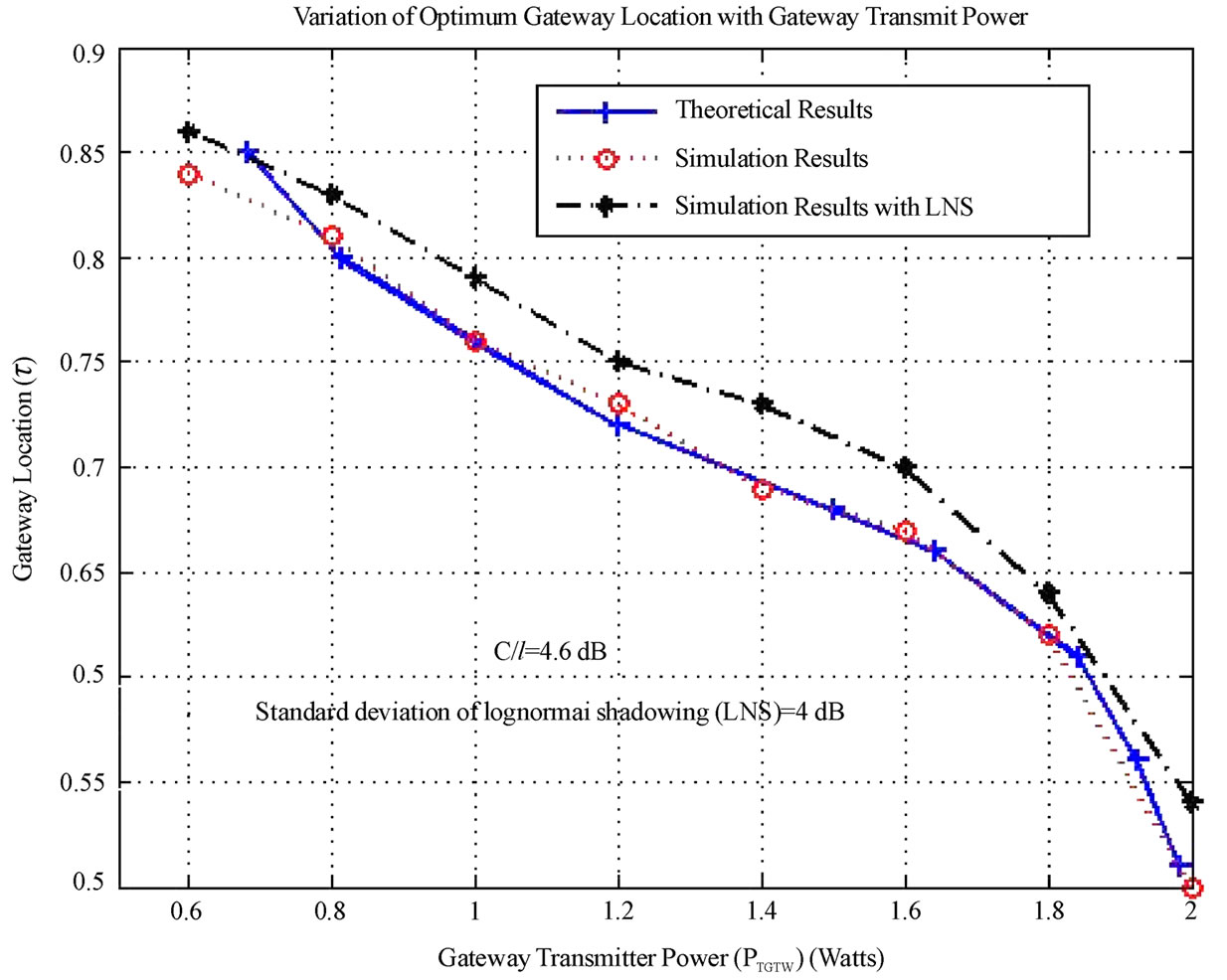
Figure 5. Variation of GTW location (τ) with gateway transmit power for α = 4.
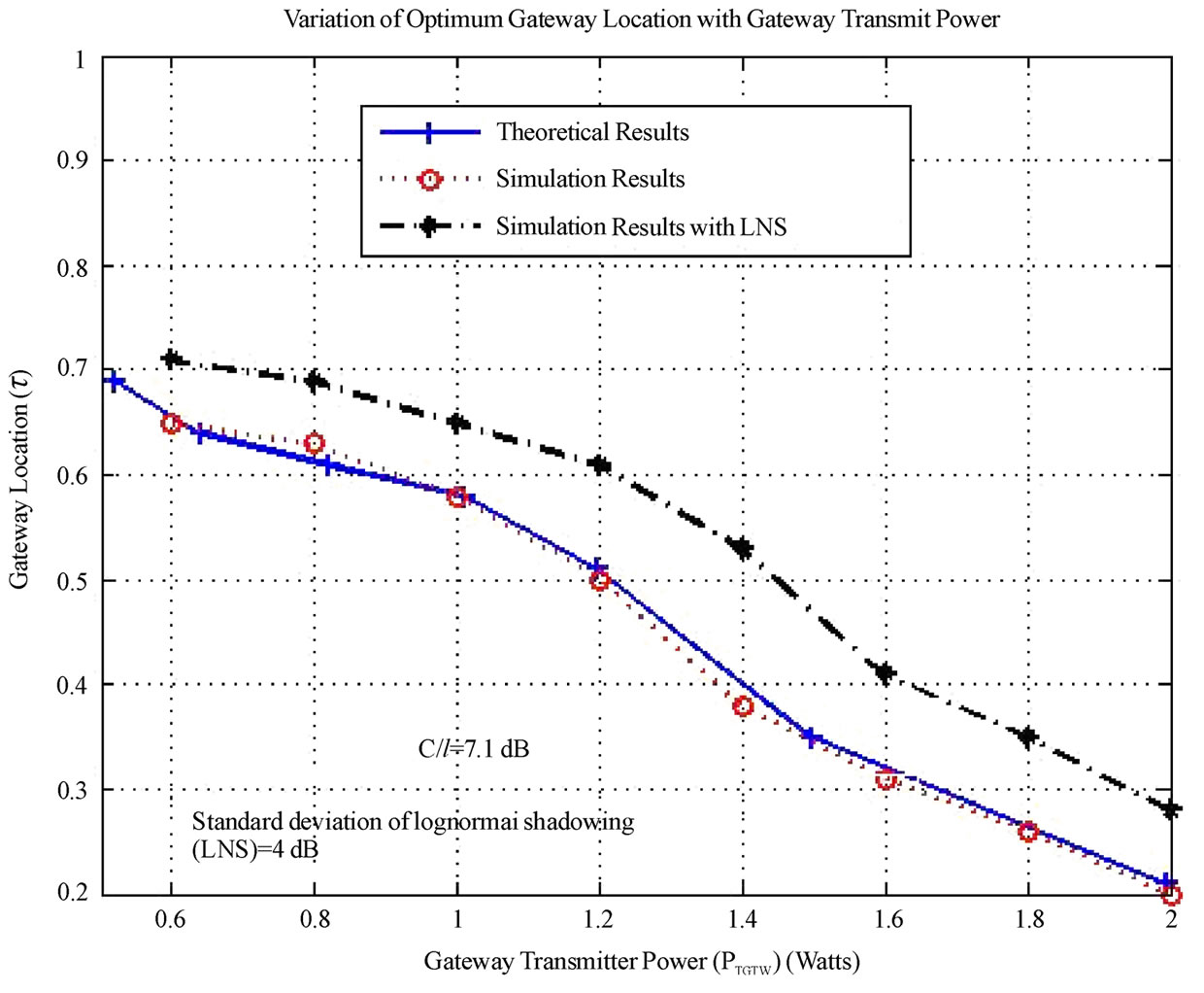
Figure 6. Variation of GTW location (τ) with gateway transmit power for α = 4.

Table 2. Minimum transmission power at GTW for a C/I of 9 dB, 11.3 dB and 14.2 dB at the receiver and the corresponding optimum location for GTW when base station transmit power is 2W.

Table 3. Minimum transmission power at GTW for a C/I of 9 dB, 11.3 dB and 14.2 dB at the receiver and the corresponding optimum location for GTW when base station transmit power is 2W.
power should also increase for high data-rate communication, even though the GTW would be close to the edge of the cell. The bold entries in Table 2 and Table 3 indicate the PGTW and τ values (optimum GTW position) when the PGTW is near 1W and 0.5 W. It can be observed from both the tables that with a decrease in the GTW transmit power (with respect to the BS transmit power), the optimum location of the GTW that would maximize the minimum C/I moves to wards the cell edge. Significantly, this is true irrespective of the C/I values.
Figure 5 and Figure 6 also show the results in the presence of lognormal shadowing. A standard deviation of 4 dB is selected, based on the realistic values for a suburban or a semi-outdoor environment [23]. It can be observed from both the figures that the behavior of the graph remains the same as compared to the case where there is no shadowing. However, for the particular gateway location, the absolute value of the required gateway transmit power increases marginally in the presence of shadowing. This shows that lognormal shadowing does affect the system performance. But, the results of the analysis on the GTW location remains still valid.
5. Conclusions
The cluster-based two-hop cellular network has been analyzed in this work for different BS and GTW transmit powers and for different possible data-rates in the system. The mathematical and numerical results indicate that for minimum data-rate transmission at the physical layer, with equal transmit power at both BS and GTW, the GTW should be located close to the center of the line joining the BS and the edge of the cell. However, for high data-rate communication, not only the minimum transmit power of both BS and GTW should be increased, but also the GTW should be moved to wards the edges of the cell. This is a significant result and indicates that the GTW location and its transmit power plays a crucial role in determining the data-rate of the two-hop cellular network. The next generation cellular networks would not only be required to support both voice and data but also multimedia transmission, which requires high and flexible data-rate between different communicating links. Hence, a further research in this direction is to modify the cluster-based design for three-hop cellular networks and to investigate the relation between minimum transmit power of BSs and GTWs and the GTW location in the cell in order to further increase the data-rate of the communication links in the cellular network.
6. Acknowledgement
The authors would like to thank Dr. Sinan Sinanovi´c and Prof. Harald Haas from the University of Edinburgh, Scotland, UK and Dr. Gabriel-Miro Muntean from Dublin City University, Ireland for their useful comments and suggestions during the initial stage of this research work.
7. References
[1] R. Ananthapadmanabha, B. Manoj, and C. Murthy, “Multihop cellular networks: The architecture and routing protocol,” in Proceedings of IEEE International Symposium on Personal Indoor Mobile Radio Communications (PIMRC’01), San Diego, USA, Vol. 2, pp. 78-82, September 30- October 3, 2001.
[2] A. Agarwal and P. Kumar, “Capacity bounds for ad hoc and hybrid wireless networks,” ACM Special Interest Group on Data Communications (SIGCOMM), Vol. 34, No. 3, pp. 71-81, July 2004.
[3] O. Dousse, P. Thiran, and M. Hasler, “Connectivity in ad hoc and hybrid networks,” in Proceedings of IEEE International Conference on Computer Communications (INFOCOM), Vol. 2, pp. 1079-1088, June 23-27, 2002.
[4] H. Vishwanathan and S. Mukherjee, “Performance of cellular networks with relays and centralized scheduling,” in Proceedings of IEEE Vehicular Technology Conference (VTC Fall’03), Orlando, Florida, USA, Vol. 3, pp. 1923-1928, October 6-9, 2003.
[5] H. Wu, C. Qao, S. De, and O. Tonguz, “Integrated cellular and ad hoc relaying systems,” IEEE Journal on Selected Areas in Communication, Vol. 19, No. 10, pp. 2105-2115, October 2001.
[6] A. Zahran and B. Liang, “A generic framework for mobility modeling and performance analysis in next generation heterogeneous wireless networks,” IEEE Communication Magazine, Vol. 45, No. 9, pp. 92-100, September 2007.
[7] K. G. J. He, K. Yang, and H. Chen, “Application of IEEE 802.16 mesh networks as the backhaul of multihop cellular networks,” IEEE Communication Magazine, Vol. 45, No. 9, pp. 82-91, September 2007.
[8] H. Haas and S. McLaughlin, “Next generation mobile access technologies: Implementing TDD,” Cambridge University Press, ISBN: 13: 9780521826228, pp. 420, January 2008.
[9] T. Rouse, S. McLaughlin, and I. Band, “Congestion-based routing strategies in multihop TDD-CDMA networks,” IEEE Journal on Selected Areas in Communication, Vol. 23, No. 3, pp. 668-681, March 2005.
[10] L. Le and E. Hossain, “Multihop cellular networks: Potential gains, research challenges, and a resource allocation framework,” IEEE Communications Magazine, Vol. 45, No. 9, pp. 66-73, September 2007.
[11] J. Cho and Z. Haas, “On the throughput enhancement of the downstream channel in cellular radio networks through multihop relaying,” IEEE Journal on Selected Areas in Communications, Vol. 2, No. 7, pp. 1206-1219, September 2004.
[12] Y. Liu, R. Hoshyar, X. Yang, and R. Tafazolli, “Integrated radio resource allocation for multihop cellular networks with fixed relay stations,” IEEE Journal on Selected Areas in Communications, Vol. 24, No. 11, pp. 2137-2146, November 2006.
[13] H. Vishwanathan and S. Mukherjee, “Performance of cellular networks with relays and centralized scheduling,” IEEE Transactions on Wireless Communications, Vol. 4, pp. 2318-2328, September 2005.
[14] M. Grossglauser and D. Tse, “Mobility increases the capacity of ad hoc wireless networks,” IEEE/ACM Transactions on Networking, Vol. 10, No. 4, pp. 477-486, August 2002.
[15] Z. Dawy, S. Davidovic and I. Oikonomidis, “Coverage and capacity enhancement of cdma cellular systems via multihop transmission,” in Proceedings of IEEE Global Communication Conference (GLOBECOM), San Francisco, USA, pp. 1147-1151, December 1-5, 2003.
[16] K. S. Hassan, H. Haas, S. Yun, Y. Lee, and S. McLaughlin, “Hybrid wireless communication system and communication method using the same,” Patent No: 200701121531. http://www.freepatentsonline.com/2007 0121531.html.
[17] H. Venkataraman, S. Sinanovic, and H. Haas, “Clusterbased design for two-hop cellular networks,” International Journal for Communications, Networks and Systems (IJCNS), Vol. 1, No. 4, pp. 369-384, December 2008.
[18] H. Venkataraman, S. Nainwal, and P. Shrivastava, “Optimum number of gateways in cluster-based two-hop cellular networks,” AEU Journal of Electronics and Communications, Elsevier, Accepted for Publication, 2008. http: //nextgenwireless.daiict.ac.in/Sub Papers/AEU May 2008 Hrishikesh Venkataraman.pdf.
[19] P. Gupta and P. Kumar, “The capacity of wireless networks,” IEEE Transactions on Information Theory, Vol. 46, No. 2, pp. 388-404, February 2000.
[20] H. Venkataraman, H. Haas, S. Yun, Y. Lee, and S. McLaughlin, “Performance analysis of hybrid wireless networks,” in Proceedings of IEEE International Symposium on Personal Indoor and Mobile Radio Communications (PIMRC’05), Berlin, Germany, Vol. 3, pp. 1742- 1746, September 11-14, 2005.
[21] H. Venkataraman, A. Mudesir, S. Sinanovic, and H. Haas, “Time slot partitioning and random data hopping for multihop wireless networks,” in Proceedings of IEEE Vehicular Technology Conference (VTC Spring’07), Dublin, Ireland, April 22-24, 2007.
[22] S. Sampei and H. Harada, “System design issues and performance evaluations for adaptive modulation in new wireless access systems,” Proceedings of IEEE, Vol. 95, No. 12, pp. 2456-2467, December 2007.
[23] 3rd Generation Partnership Project (3GPP), Technical Specification Group Radio Access Network, “Selection procedures for the choice of radio transmission technologies of UMTS,” 3GPP TR 30.03U, May 1998. Retrieved November 30, 2008, from http://www.3gpp.org/ftp/ Specs/html-info/3003U.htm.