Journal of Software Engineering and Applications
Vol. 6 No. 7 (2013) , Article ID: 34132 , 18 pages DOI:10.4236/jsea.2013.67045
Modeling Rules Fission and Modality Selection Using Ontology
![]()
1MMS Laboratory, Université du Québec, École de Technologie Supérieure, Montreal, Canada; 2LISV Laboratory, Université de Versailles-Saint-Quentin-en-Yvelines, Paris, France.
Email: atef.zaguia.1@ens.etsmtl.ca,moeiz.miraoui.1@ens.etsmtl.ca, ctadj@ele.etsmtl.ca, rca@prism.uvsq.fr
Copyright © 2013 Atef Zaguia et al. This is an open access article distributed under the Creative Commons Attribution License, which permits unrestricted use, distribution, and reproduction in any medium, provided the original work is properly cited.
Received May 6th, 2013; revised June 7th, 2013; accepted June 15th, 2013
Keywords: Multimodal system; Multimodal fission; Modality; Ontology; Interaction context; Pattern
ABSTRACT
Researchers in computer science and computer engineering devote a significant part of their efforts on communication and interaction between man and machine. Indeed, with the advent of multimedia and multimodal processing in real time, the computer is no longer considered only as a computational tool, but as a machine for processing, communication, collection and control. Many machines assist and support many activities in daily life. The main objective of this paper is to propose a new methodological solution by modeling an architecture that facilitates the work of multimodal system especially for a fission module. To realize such systems, we rely on ontology to integrate data semantically. Ontologies provide a structured vocabulary usedas support for data representation. This paper provides a better understanding of the fission system and multimodal interaction. We present our architecture and the description of the detection of optimal modalities. This is done by using an ontological model that contains different applicable scenarios and describes the environment where a multimodal system exists.
1. Introduction
The communication plays animportant role in our daily life as it allows people to interact with each other as individuals or groups. In fact, humans have a sophisticated ability to communicate and exchange information that is due to the division of the language, as well to the common comprehension of the operation of the things and an implicit understanding of the daily situations.
Since many years, the researchers want to find solutions to share common understanding of the structure of information among people or the machines and to re-use this knowledge in order to allow the creation of intelligent machines or systems being understood by the users, perceiving his environment and reacting in ways to maximize the success rate of understanding and responding. Among these systems the multimodal systems that permit to combine in input and/or in output several modalities [1] dynamically (Figure 1).
These systems receive their input from sensors and gadgets (camera, microphone, etc.) and they interpret and understand these inputs [2-4]. This is known as fusion process.The resulting command is then executed in the output gadgets (fission process) (screen, speakers, projector etc.). This is known as fission process. Combining these modalities in the input/output is called multimodality [5,6].
A known example of these systems is the Bolt system “Put That There” [7], where the author used the gesture and speech to move objects.
These systems improve the recognition and the understanding of the environment command (user, robot, machine etc.) by the machine.
But understanding is only possible if these systems or these machines are equipped with a knowledge base.
Knowledge includes all necessary components to achi-
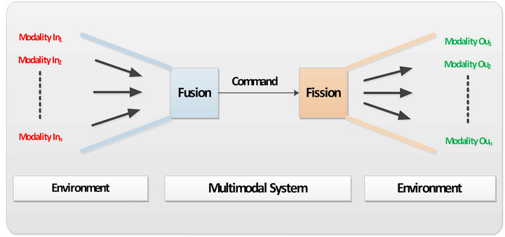
Figure 1. Multimodal system.
eve the annotation of the data, such as it can be performed by experts in a particular field.
Several studies have focused on the improvement of intelligent systems and especially the creation of systems that enable semantic interoperability, which means the systems will not only exchange data with each other in a given format (e.g. the string “Canada”) but also must have the same meaning for both parties (a Country).
So the main goal is to find a way to present data so that the machines, the users, the applications can understand. The most adequate solution is ontology [8].
The ontology will have a good impact in multimodal systems and specially for fission module [9].
The fission module is a fundamental component of multimodal interactive system. It is mainly used at the output. Its role is to subdivide the requests/commands made by the user to elementary subtasks, then associate them to the appropriate modalities and to present them in the available output media [10]. The meaning of the command may vary according to the context, the task and the services. This paper is focused on the fission process. We propose a new methodological solution by modeling an architecture that facilitates the work of a fission module, by defining an ontology that contains different applicable scenarios and describes the environment where a multimodal system exists. The proposed architecture has three main characteristics:
• Openness: handling a large number of modalities that prevents the restriction in its application to specific domains.
• Flexibility: the use of ontology makes the description of an environment and its scenarios easier.
• Consistency: the description of the most potential objects and scenarios of the environment.
This paper discusses these characteristics by explaining the architectural design of the proposed solution.
The rest of this paper is structured as follows. Section 2 presents the problems related to the fission processand highlights the novelty of our work. Section 3 presents related researches. Sections 4 to 6 present the design of the architecture, the interaction context and the ontology which we will use to solve the problem “How to present fission rules and modality selection for multimodal systems?”. Sections 7 and 8 describe our proposed fission algorithm and a scenario respectively. Conclusion is presented in Section 9.
2. Problematic and a Proposed Solution
A system can be called multimodal, if it provides input or output combiningmultiple modalities, so that the resulting communicative system is more efficient.
In our work, we focus specifically on 1) the services connected to the output: multimodal fission and 2) the creation of multimodal interaction system.
The first challenge is: what are the required modules to build the architecture of a fission system? Here, we will specify, define and develop all necessary components of the system. We will also show how they communicate.
The second challenge is how to select the output modalities considering that the state of the environment is dynamic? Here we will use the interaction context [11] to resolve this problem.
The third challenge is how to subdivide a command to elementary subtasks? Here we will use a predefined pattern for all possible scenarios.
The forth challenge is how to select the appropriate and available modality (ies) for a given sub-task using predefined patterns that describe a modality (ies) selection.
The fifthchallenge data modeling and how do we make it dynamic, flexible, easy to update and describe it easily? We will use ontology as a knowledge base.
The sixthchallenge concerns validationof our proposed architecture (formalism)? We focus more closely on the design, specification, construction and evaluation of our fission architecture. We use the CPN-Tools (Colored Petri Net-Tools) to modulate and simulate our architecture.
To summarize, our goal is to develop a fission component for multimodal interaction. We also elaborate an efficient fission algorithm. To achieve our goal, we create a context sensitive architecture, able to manage multiple modules and modalities and automatically adapts to dynamic changes of the interaction context.
3. Related Work
The multimodal interaction is a regular characteristic for each activity and human communication, in which we speak, listen, watch, etc., alternately or simultaneously.
The objective of the research in multimodality is to develop a flexible system capable to manipulate many modalities. We assume that the environment has a rich collection of different media/modality components. The fission module is a crucial component of multimodal system. But most research in multimodal systems [12] focus more on the fusion than the fission. We can support our point by “There isn’t much research done on fission of output modalities because most application use few different output modalities therefore simple and direct output mechanism are often used” [13]. Also the allocation of output modalities was rather hard coded than based on intelligent system for the early multimodal system.
In general, the process of fission is the manner to segment the data which will be presented to the user dependingon availabilityof modalities. For Foster, [14] multimodal fission is the process of realizing an abstract message throughoutput on some combination of the available channels [9].
According to [15] and [14], the fission process goes throw three main stages: 1) Select and organize the content: this step consist of selecting and organizing the content that will be presented. 2) Modality (ies) selection: specifies the modalities that can display or present the command. 3) Coordination of outputs: Coordinate outputs for each channel in order to create a coherent presentation.
In [16], Rousseau et al. describe a conceptual modal (WWHT (What-Which-How-Then)) for the design of multimodal system and the presentation of information in the output.This model is based on concepts What, Which, How and Then: 1) what is the information to present? 2) Which modalities should be used to present this information? 3) How to present this information using these modalities? and 4) then how to handle the evolution of the resulting presentation?
In [17], Benoit et al. present a very simple multimodal fission system that detectsthe state of the driver. They capture information from sensors installed in the car and then they test if the values entered are in some specific intervals and through this test, the system will generate alerts.
We propose a new solution for the fission module through modeling patterns that deal with different modalities and different possible scenarios, and by creating a knowledge base that contains these patterns. The adoption of this solution will facilitate the work of a fission module by giving it the most meaningful combinations of data.
4. Architectural Design
In this section, we will describe our proposed architectural design.The architecture is composed of four main modules (Figure 2):
Environment: involves the physical geographical location where the multimodal system exists.
Modality (ies) Selection: the goal of this module is to select the adequate and available modality (ies) according to a specific context. This module is presented in Section 5.
Fission: it is the most essential part of our architecture. This module permits to subdivide a command to elementary subtasks by finding the match with all patterns described in the ontology. These patterns are generally defined with two parts, namely, problem and solution. Therefore, we must define the problem and the solution so that we can talk about patterns.
In our case, the problem is the command parameters (the words that compose the command). The solution consists of all the possible subtasks for this command. Figure 3 shows an example of a pattern.
The system sends a query with the problem parameters to find the matching pattern in the ontology.
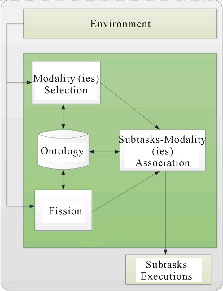
Figure 2. General approach of multimodal fission system.
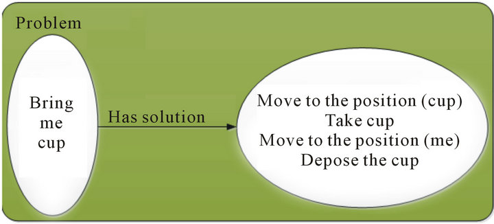
Figure 3. Example of pattern.
Subtasks-Modality (ies) Association: its purpose is to associate for each subtask generated by the fission module to the appropriate and available modality (ies). In this part, we also use patterns as predefined models that describe a modality (ies) selection. In our work, a modality pattern is composed of: 1) Problem composed of the components: Application, parameter, priority, combination, scenario and service and 2) Solution composed of the chosen modality. For more details concerning scenarios selectionand modalities selection, the readers can refer to [18].
Ontology: is the knowledge base that describes every detail in the environment, the modality patterns and the patterns of fission that occurred previously.
5. Interaction Context
In this work, a modality refers to the logical structure of man-machine interaction, specifically the mode by which data is presented in output as a result between a user and computer. Using natural language processing as basis for categorization, we classify output modalities into 3 different groups and for every group we present some media devices that support these modalities [10]:
• Vocal Output (VO)—a sound is produced as data output: the user obtains the output by listening to it. For this modality, we can use different media such as speaker, headset and speech synthesis system.
• Manual Output (MO)—the data output is presented in such a way that the user would use his hands to grasp the meaning of the presented output. This modality is commonly used in interaction with visually-impaired users. For this modality we can use Braille, overlay keyboard.
• Visual Output (VIO)—data are produced and presented in a way that the user read them. For this modality we can use for instance ascreen, printer, projector, TV.
A modality is appropriate to a given interaction context if it is found to be suitable by checking the parameters of the user context, the environmental context and the system context.
5.1. User Context
User handicap—it affects the user’s capacity to use a particular modality. We note four handicaps, namely Manual handicap, Muteness, Deafness, and Visual impairment.
User location—we differentiate between fixed/stationary locations, such as being at home or at work where user is in a controlled environment to that of a mobile location (on the go) where user generally has no control of what is going on in the environment.
5.2. Environmental Context
Noise level—the noise definitely affects our ability to use audio as data input or receiving audio data as output.
Brightness of workplace—The brightness or darkness of the place (i.e. to the point that it is hard to see things) also affects our ability to use manual input and modalities.
Darkness of workplace—The darkness of the place also affects our ability to use manual input and modalities.
5.3. System Context
The capacity and the type of the system that we use are factors that determine or limit the modalities that can be activated.
To recapitulate, a modality is considered adequate when it verifies all the parameters listed before. This is shown by a series of relationships given below:
These relationships are used in the simulation to select the appropriate modalities. For more details concerning selecting the suitable modalities, the reader can refer to [11,19,20].
6. Ontology
An ontology is the basis of the representation or the modeling of knowledge. This area is the brainchild of researchers representing various knowledge of today's world. This knowledge will be used by machines to perform reasoning. This knowledge is expressed in the form of symbols to which we give a “semantic” (meaning).
Ontology is a “formal and explicit specification of a shared conceptualization” [21]:
Formal specification: comprehensible by a machine.
Explicit specification: the concepts, relations, functions, constraints, axioms are explicitly defined.
Conceptualization: abstract model of a part of the world whom one wants to represent.
Divided: knowledge represented is shared by a community.
Within ontology, the terms are gathered in the form of semantic concepts (or classes) as shown in the example of Figure 4.
Ontology allows:
• To give a shared vocabulary to describe a field: for example (Figure 1) the Shape_2D concept represents the class of the shape 2D.
• To provide primitive typing classes and relations: Shape_2D is a subclass of Shape triangle is an authority of the Shape_2D concept.
• To reason: infer new facts from those we have already. It follows that triangle, in the previous example, is also an instance of concept Shape.
There exist several languages and tools to present ontology. Some of early languages are Ontolingua [22] and OKBC [23]. Recent ones, based on xml, include RDF [24], DAML + OIL [25] and OWL [26]. We can also find ontology development tools such as the server in university of Stanford Knowledge Systems Laboratory, Protegé [27], OilEd [28] and OntoEdit [29].
The purpose of ontology is to model a set of knowledge in a given field with a form usable by the machine. It provides a representative vocabulary for a given domain, a set of definitions and axioms that constrain the
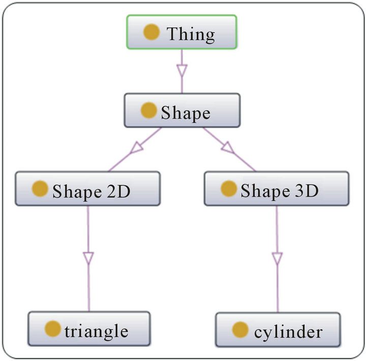
Figure 4. Example of ontology for the shape.
meaning of the terms of this vocabulary in a sufficient manner to allow a consistent interpretation of the data represented using this vocabulary. Ontology is used as a way to formalize information to obtain a knowledge base.
In this section we present the most essential of our ontology. It details the home context. This ontology can be upgraded to target other contexts such as hospitals, workplace, etc. Assuming that our system will helps or assists a user in the house.
In our case, we will use Protegé [30] to develop our ontology.It is a free tool and the most widely used ontology editor. An open-source, it was developed by the university Stanford.It has evolved since its first versions (Protected-2000) to integrate from 2003 the standards of the semantic Web and in particular OWL. It offers many optional components: reasoners, graphical interfaces.
The general view of our ontology is presented by Figure 5. It is composed of several classes:
Environmental Context: It describes the state of the environment, such as determination of the noise level. It is understood that the use of the audio modality is affected by this information. If the noise level is high, the audio modality will be disabled. As we can see in our ontology (Figure 6) the vocal modality is only active when the noise level is average or low.
Coordinates/Place: Used to locate various objects, places and people in the environment (Figure 7).
User Context: It describes the location and status of the user. It identifies the user’s ability to use certain modalities. For example, the system disables the display modality if it detects that the user is visually impaired and disables the vocal modality if it detects that the user is in a library.
Modality: It contains various modalities that can be used by the system to present a given subtask.
Model: Contains a set of models that represent different combinations of events for different scenarios (user commands). This class will allow us to validate the meaning and the grammar of a command. Here, it presents the
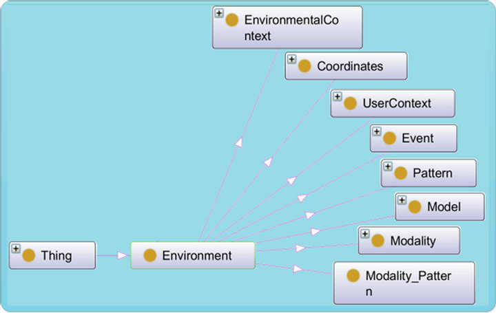
Figure 5. General view of ontology.
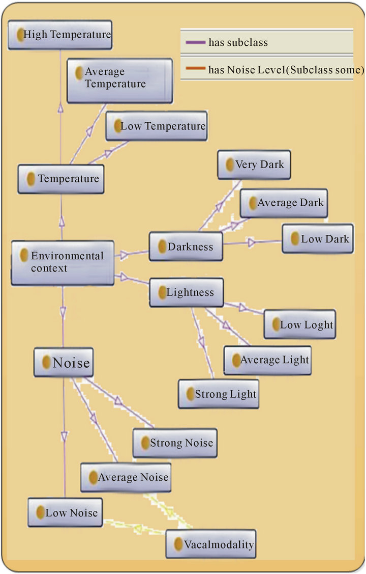
Figure 6. Environment context.
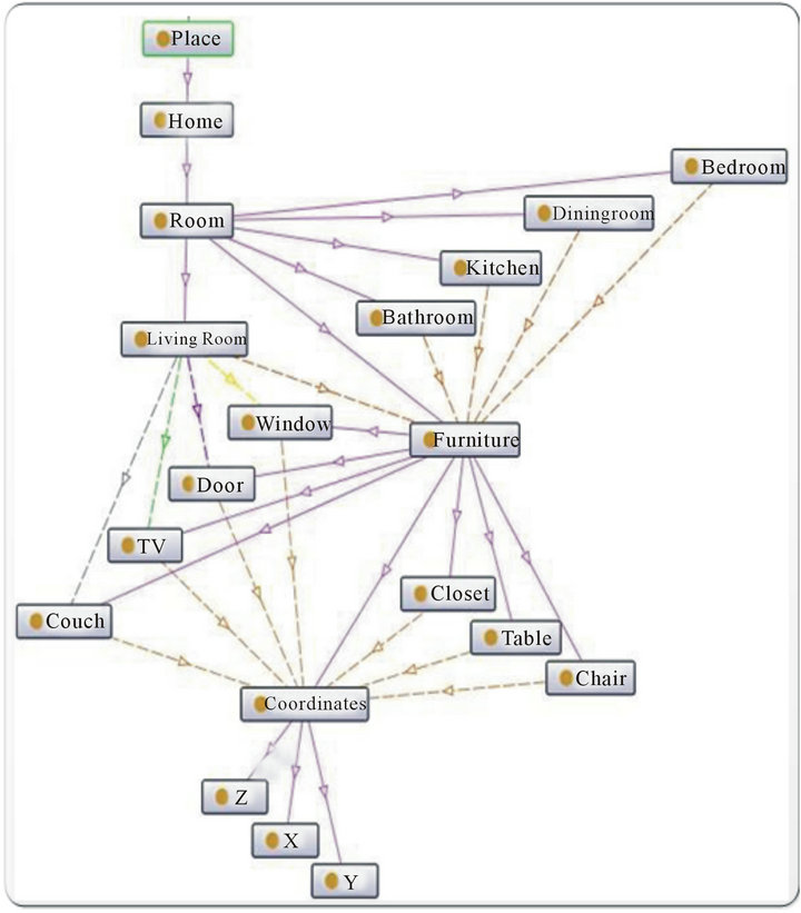
Figure 7. Place concept and its subclasses.
problem for a given pattern.
Pattern_Scenario: Contains all possible sub-tasks for an order. It presents the solution for a given pattern.
Modality_Pattern: Allows us to select the appropriate modality for each subtask.
Event: It is the event that triggers the fission process. It presents our complex command. The following describes in details the most important class developed for our system.
6.1. Modality Class
As we can see in Figure 8, this class presents the different output modalities that we can use to present our data/ information.
It composed of three main subclasses {Manual Modality, Vocal Modality, Visual Modality} and every subclass has the adequate medias.
6.2. Event Class
This class presents the classes that can form a command (Figure 9), it presents the possible combination of classes to form a command:
1) Action: it presents the verbs that the command can
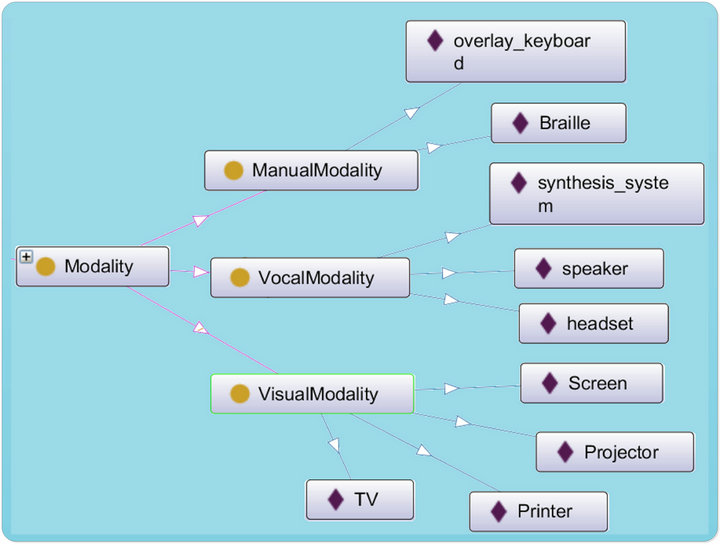
Figure 8. Modality class.
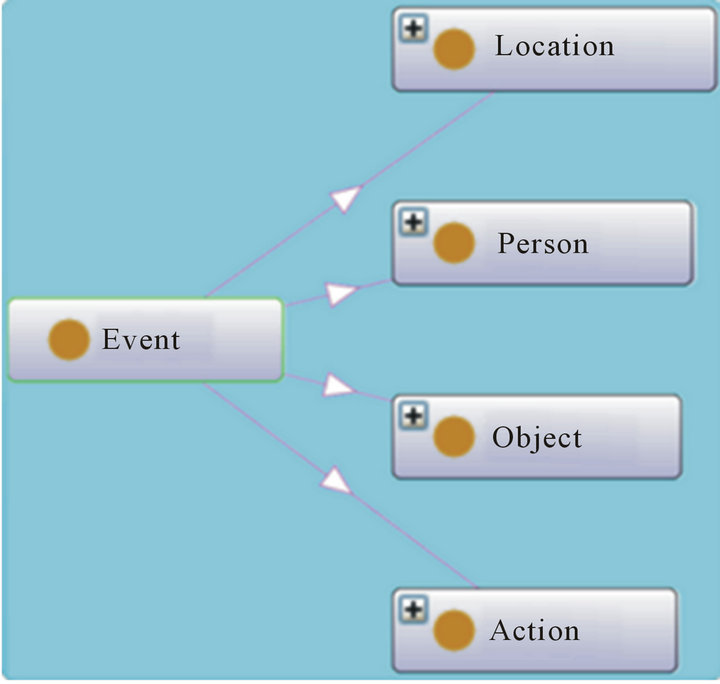
Figure 9. Event class.
contain (vocabulary). We divided it on three categories:

a) Action for Location: it presents the verbs that refer to places. Here some of these verbs:

b) Action for Person: it presents the verbs for persons. For instance:

c) Action for Object: these are verbs that act on objects. It has been divided in tow classes to allow us to manage the meaning of a command, for example "move the wall" should be rejected.

d) Action for Movable Object: represents the verbs for objects that can be moved.

e) Action for Non Movable Object: represents the verbs for objects that can be moved.

2) Location: it presents different locations that we can find in a command. We subdivided it in three categories:

a) Indoor: we defined locations within the house, such as:

b) Outdoor: we defined the locations outside of the house.

c) Intended Location: presents the prefix for locations. These permit to precise the position of an object. For example “put the pen inside the box.”
Here some these prefix:

3) Object: it presents the different objects that we can use.
a) Average Object: it presents the average objects in the environment, such as

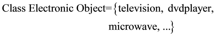
b) Electronic Object: it presents the electronic objects. For instance:
c) Heavy Object: it presents the heavy objects. For example:

d) Food: it presents the foods. For example:

e) Liquid: it presents the liquid for example:

f) Movable Object: it presents the movable objects, such as:

g) Non Movable Object: it presents the non-movable objects, for example:

h) Object for Food: it presents the objects for food, for example:

i) Object for Liquid: it presents the objects for liquid, such as:

j) Small Object: it presents the small objects. For example:

4) Person: it presents the relations between persons. For instance:

6.3. Grammar Model
This class will allow us to validate the meaning and the grammar of a command, we have defined several models. Each model includes two/several subclasses of the class “Event” in a predetermined order. For example Figure 10.
• Model 01 is composed of four subclasses: Action for Movable Object, Small Object, Intended Location and Average Object. These subclasses are defined in the model in a predefined order as seen in Figure 10:
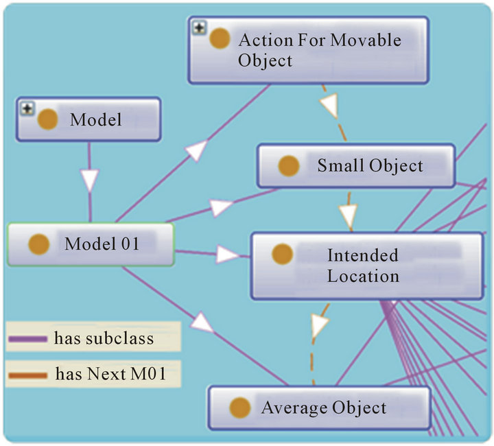
Figure 10. Example of a model.


An example of this model: “Put the pen on the table”. In this case:


In the following, we show some other models we have modeled:
• Model 02:


For example “Put the chair behind the wall”.
• Model 03:

For example “drop the cup”.
· Model 04:

For instance “give the pen to my father”.
· Model 05:

For instance “close the door of the kitchen”.
These models enable us to process a large variety and complex commands.
6.4. Fission Patterns Class
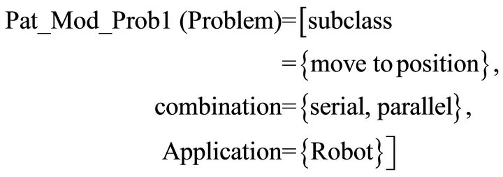
This class describes the different scenarios. These scenarios saved in patterns form which are mainly composed of two parts problem and solution, as detailed in [18]. Figure 11 shows an example of pattern.
As we can see class (pattern 1) has two subclasses (Problem, Solution):
• Has Pattern Pro1 (yellow Arrow) class Pattern_P 01 with parameters {Bring, Model 01 (as shown in Figure 10)}.
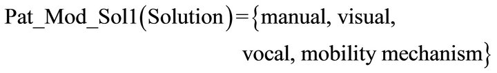
• Has Pattern Sol1 (orange Arrow) class Pattern_S 01 with parameters {1-move to the destination context, 2-move to the object, 3-take the object, 4-move to the position, 5-depose the object”}.
6.5. Modality Pattern Class
Here we present the class of Modality_Pattern (Figure 12). That permits, to select the adequate modalities for a given subtask. As we mention in the previous section, this pattern is quite similar than Fission Pattern.
Figure 12 shows an example of Modality_Pattern, the class Modality_Pattern1 is composed of two subclasses:
7. Fission Algorithm
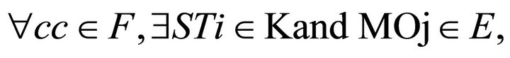
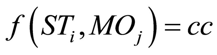
In general, the fission rule is simple: if a complex command (CC) is presented, then a set of sub-tasks with the modalities (and its parameters) are suitable deducted. Multimodal fission can be represented by the function:

With: 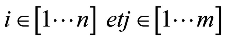
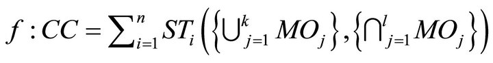 (1)
(1)
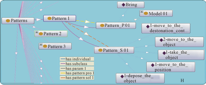
Figure 11. Example of fission pattern.
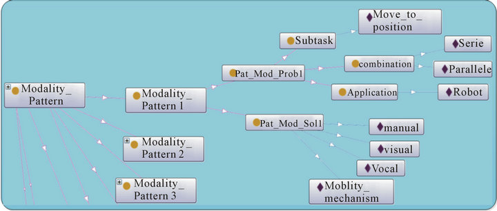
Figure 12. Example of modality_pattern.
with: STi = sub-task i; MOj = output modality i; CC = complex command. l and k are different from m and n because it depends on the sub-tasks. For example, for some sub-task we will use just two terms even if we have three modalities available.
In equation (1), the symbol ![]() indicates that we can use either one or several modalities to present a sub-task. For example, if we present a text to the user, we use audio or display. The symbol
indicates that we can use either one or several modalities to present a sub-task. For example, if we present a text to the user, we use audio or display. The symbol ![]() indicates that we use the available modalities together to present a sub-task.
indicates that we use the available modalities together to present a sub-task.
Figure 13 describes the steps involved in the fission process. In this diagram, n numbers of commands serve as an input to the system. The steps undertaken are as follow:
Step-1: the system extracts every word from the command
Step-2: for every word, the vocabulary stored in the Vocabontology is checked.
Step-3: from each wordi is extracted vocabi and is concatenated in the same order as in the original command. The model of the command is therefore obtained.
Step-4: a query is sent to the ontology Grammar Model to look if the model is in the ontology.
Step-5: if the model is found, we proceed with step 7 otherwise we proceed with step 6.
Step-6: the command is not valid and a feedback is sent to the user.
Step-7: a query is sent to find matching pattern fission from predefined patterns stored in the Pattern Fission ontology.
Step-8: if no matching pattern is found, a feedback is sent to the user.
Step-9: for every subtask we associate the adequate and the available modality (ies). This is done by sending a query to find the matching pattern modality.
This algorithm is divided in two parts: the purpose of the first part (Figure 14) is to check if the command is valid.The second part concerns the fission process (Figure 15).
The inputs of the fission algorithm are the command CC and the model created with concatenation of all vocabi of the command (Figure 15).
We create the pattern problem; composed of the {model and the action verb of the command}; and then we search the matching of the pattern problem in the ontology (get Pattern Solution (pattern-problem)).
If asolution is found, subtasks are created and for each one, the appropriate modality (ies) is determined (get Subtasks Modalities (subtask)).
If we find a similar matching (Part Matching Model (pattern-problem)), we try to find the missing subtask (create Subtasks Missing ()) and we send feedback to the user.
We will follow these steps for our simulation in the
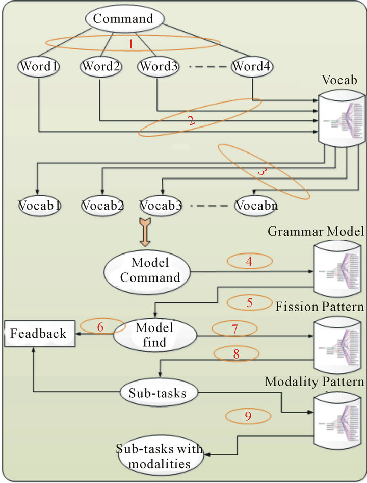
Figure 13. Stages of fission process.
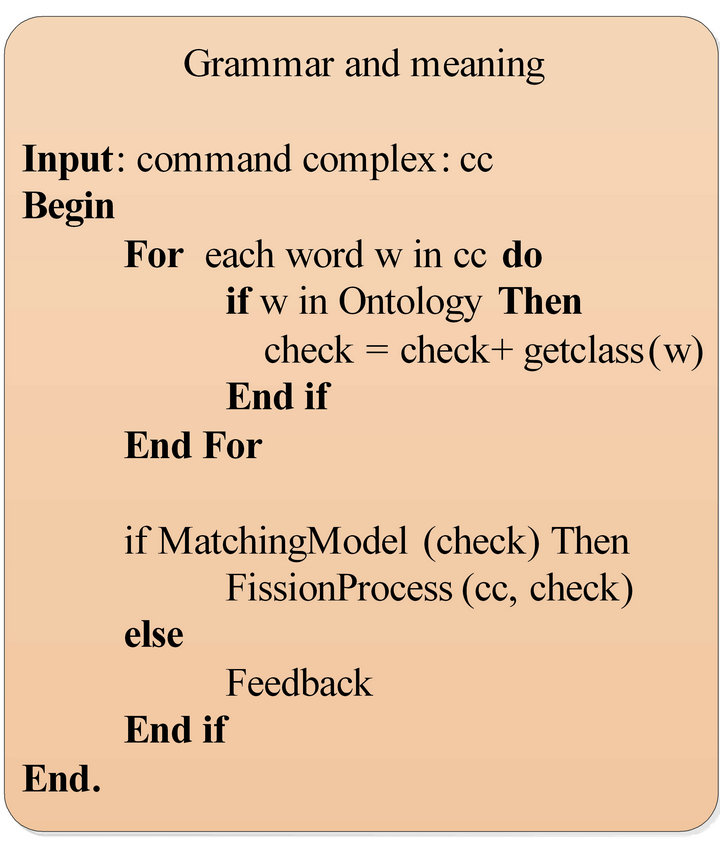
Figure 14. Fission algorithm (Grammar and meaning).
next section.
8. Application Scenario and Simulation
To understand the mechanism of fission we will demonstrate a simulation of a scenario.
In this scenario, we assume that in our multimodal system, a robot moves an object from its initial position to another location. For instance “Bring me the cup”.
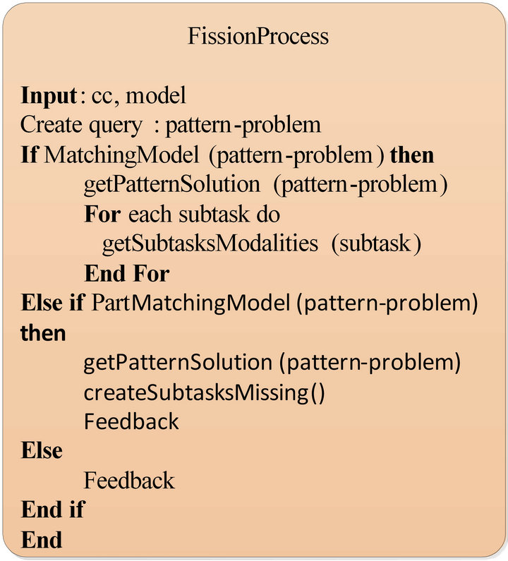
Figure 15. Fission algorithm (fission process).
We first model and simulate the architecture defined in Figure 3. The steps of each strategy are modeled using the colored Petri Net [31] formalism and simulated using the CPN Tools [32].
Figure 16 shows the general view of the architecture. It is composed mainly by 8 modules:
Generator: this module generates events as random numbers to select a command in the place “command”. As shown in Figure 16, the system processes the command “Bring me the cup”.
T_parser: this module decomposes the command into words.
T_Fission: its role is to divide the command to elementary subtasks.
T_Grammar: permits to verify the meaning and the grammar of the command.
Modality(ies) Selection: this module allows to select the available modalities depending on the state of the environment.
T_Subtask-Modality_Association: as its name indicates, it associates for each subtask the appropriate modality (ies).
Ontology: it is a container that stores the patterns as ontology concepts, the models and the vocabulary.
The diagram in Figure 17 demonstrates a Petri net showing the parser processing. As we can see, this module has as an input, the command of type string and the output a list of words. In transition “T_Parser”, the system creates a list of all the words in the command and then the transition “Add indication end of command” add an indication at the end of the command to differentiate it with other commands.
The diagram in Figure 18 show the grammar module reacts with the ontology to verify the validity of the command. This modulehas as the first input a list of stringsobtainedfrom the parser and the second input, is a set of two elements of type string and Boolean, obtained from the ontology. The string type refers to the model of the command found in the ontology and the Boolean one determines if the command is valid or not.
We also obtain two outputs: the first one is a feedback module to prevent the user in case of an invalid command. The second output is connected to the fission module when the command is valid.
As we can see, the system receives the list of words of the command and sends them, one by one, to the ontology (transition “send word”) by checking the length of the list and the number of the words that are already sent (places “com” and “command lengh”).
When this module receivesthe answer from the ontology (place “Model of command”), it verifies the value of the Boolean element “modelGram”: 1) if true: sends the model “concatGramF” to the fission module (place “to Fission”) otherwise 2) sends to the feedback module (place “to feedback”).
The diagram in Figure 19 is a continuation of Figure 18. This module sends the words to “ontology_Vocab” and then concatenates the vocab for every word to create the model of the command. As we can see in the place “word from grammar”, we check the equivalence of vocabularyof all the words of the command.
Figure 20 shows the steps to get the vocab of every word. All the vocabularies are stored in the place “vocabulary”.The system searches for every word the equivalent vocab, and sends the result. As we can see in Figure 20, the result sent for “Bring” is “AFMO”.
After the model of the command is created, the system sends the model of the command to the ontology to look if this model exists in the ontology (Figure 21). The model of theexample “Bring me the cup” is “AFMO P MO”. In the place “Model Test” we can see the result of searching (“AFMO P MO”, true). The command is there fore verified grammatically and has a correct meaning.
After the verification is done, the fission process begins. The fission module sends a query to the ontology to find the matching pattern stored in the ontology. As we can see in Figure 22, in the place “pattern”, the parameters of pattern problem are “model P” and “action P”. These parameter are compared with the parameters of command “(query Pat A, query Pat M)” to find the mating pattern. The solution pattern is “supList”.
Theresult of our command is [“1-move to the destination context”, “2-move to the object”, “3-take the object”, “4-move to the position”, “5-depose the object”] as shown in Figure 22. This result represents the subtasks for our command. Adding the first subtasks “move to the destination context” will allow as managing orders for other contexts position. For our example the destination context is “kitchen” since the cup is usually in the kitchen.
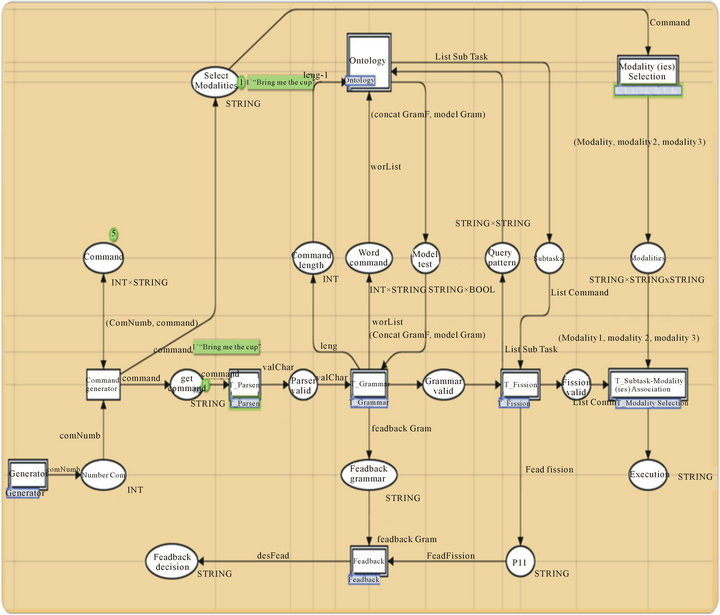
Figure 16. General view of our architecture.
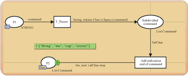
Figure 17. Parser processing.
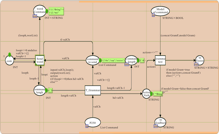
Figure 18. Grammar.
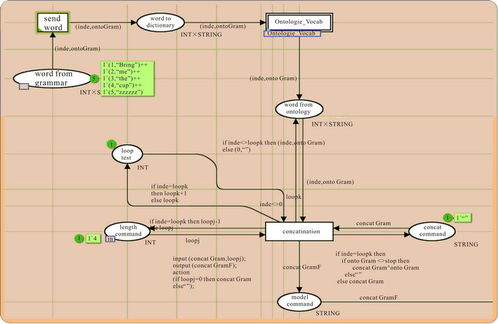
Figure 19. Ontology-processing.
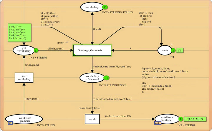
Figure 20. Vocabulary processing.
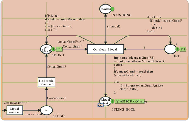
Figure 21. Model processing.
After we get the subtasks, the fission module send the results to the T_Subtasks-Modality (ies) association. Selection of the available modality (ies) is performed according to state of the environment.
Figure 23 shows the process of selection of modality (ies). There are three types of modalities: “audio”, “visual” and “manual”. The system starts getting the information from the sensors in the environment, in Figure 23 we simulate it by the places:
• “environmental context for light” is set to a value from 1 to 10.
• “environmental context for noise” is set to a value from 1 to 10.
• “Manual Modality”.
The system chooses randomly the value of noise andthe brightness in the environment. If the noise is under 5 we activate the audio modality (ies) otherwise we disable it (Transition: “audio Contexts Checking”) and if the location of the user is for example in the library, we deactivate the audio automatically (place “User location”).If the user is mute or deaf, the audio modality is deactivated (place “User Profile”). If the light is higher than 5, we activate the visual modality (ies), otherwise we disable it (transition: “Visual conext test”).
In our case, we can see that the only activated modality is (“visual”, “ ”, “ ”).This is performed by checking all the active modalities by the transition “context verification”.
Figure 24 shows the final processing of our simulation: modality (ies) and subtasks associations. This modulereceivesas an input, the list of subtasks presented by the place “list Subtasks” and the list of modalities presented by the place “List Modalities”.
In our case, the first input is the first subtask “move to the destination context” and the second input is (“visual”, “ ”, “ ”).
Figure 25 is the continuation of Figure 24 showing the result of the association of modalities. For the first subtask, the result is (“1-move to the destination context”, [“mobility mechanism”, “TV (on)”, “printer (on)” ]) since the system detects only visual modality,it can show the track on TV and printer as they are ON and the system will use “mobility mechanism” as services related to the output modalities to move.
9. Conclusions
The role of ontologies is to improve the communication between human, but also between human and machines and finally between machines.
In this paper we demonstrate the reasons of the use of ontology such as sharing common understanding of the structure of information, enabling reuse of domain knowledge and making domain assumptions explicit. And we present our ontology to solve our problems that consist to model our data, make it dynamic, flexible and easy to update.
We presented architecture to identify different modalities of output and split data on these modalities using patterns stored in the knowledge base.
The architecture was modeled using colored Petri net formalism and simulated with the CPN-Tools.
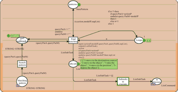
Figure 22. Matching process.

Figure 23. Modality (ies) selection process.
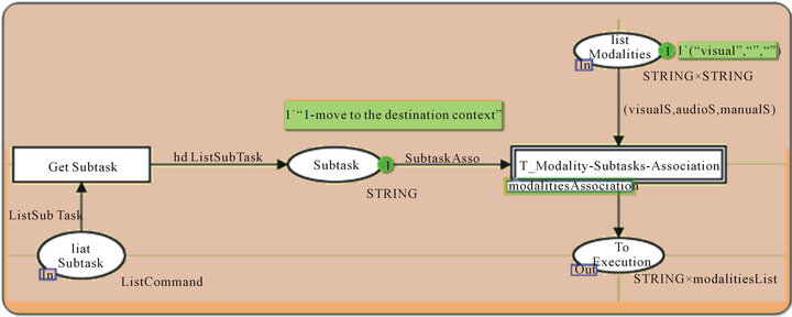
Figure 24. Modality (ies)—subtasks association processing 1.
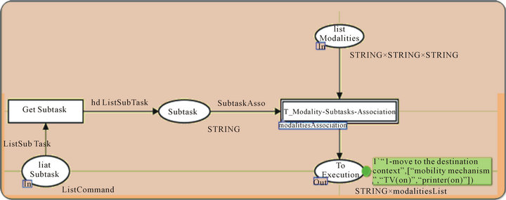
Figure 25. Modality (ies)—subtasks association processing 2.
There are many fields where improvements of the human-system interaction are open to exploration. In fact, a system which is able to take advantage of the environment can improve interaction. This can reach an extent at which the system (robot/machine) is able to use human beings’ natural language. We believe that this work contributes to the advancement of fission research in the field of multimodal human-machineinteraction.
This system provides a good level of autonomy and a good capacity for decision-making, which can be an effective way to help or assist user and especially in inaccessible places, or considered as a danger to humans.
10. Acknowledgements
We wish to acknowledge the funds provided by the Natural Sciences and Engineering Council of Canada (NSERC) which support the financial needs in undertaking this research work.
REFERENCES
- S. Oviatt, “Multimodal Interfaces,” In: S. Oviatt, Ed., The Human-Computer Interaction Handbook, Lawrence Erlbaum Associates Inc., Hillsdale, 2003, pp. 286-304.
- A. Zaguia, et al., “Using Multimodal Fusion in Accessing Web Services,” Journal of Emerging Trends in Computing and Information Sciences, Vol. 1, No. 2, 2010, pp. 121-138.
- D. Lalanne, et al., “Fusion Engines for Multimodal Input: A Survey,” The 11th International Conference on Multimodal Interfaces, Cambridge, 2-6 November 2009, pp. 153-160.
- P. Feiteira and C. Duarte, “Adaptive Multimodal Fusion,” Universal Access in HCI. Design for All and eInclusion, Lecture Notes in Computer Science, Vol. 6765, Springer Berlin Heidelberg, Berlin, Heidelberg, 2011, pp. 373-380. doi:10.1007/978-3-642-21672-5_41
- C. Lauer, “Contending with Terms: ‘Multimodal’ and ‘Multimedia’ in the Academic and Public Spheres,” Computers and Composition, Vol. 26, No. 4, 2009, pp. 225- 239. doi:10.1016/j.compcom.2009.09.001
- N. O. Bernsen, “Multimodality Theory,” In: D. Tzovaras, Ed., Multimodal User Interfaces, Springer, Berlin, 2008, pp. 5-29. doi:10.1007/978-3-540-78345-9_2
- R. Bolt, “Put-That-There,” Voice and Gesture at the Graphics Interface ACMSIGGRAPH Computer Graphics, Vol. 14, No. 3, 1980, pp. 262-270. doi:10.1145/965105.807503
- N. Guarino, D. Oberle and S. Staab, “What Is an Ontology?” In: S. Staab and R. Studer, Eds., Handbook on Ontologies, Springer Berlin Heidelberg, Berlin, Heidelberg, 2009, pp. 1-17.
- M. E. Foster, “State of the Art Review: Multimodal Fission,” University of Edinburgh, COMIC Project 2002.
- W. A. Carnielli and C. Pizzi, “Modalities and Multimodalities,” Springer, Berlin, 2008.
- A. Zaguia, et al., “Interaction Context-Aware Modalities and Multimodal Fusion for Accessing Web Services,” Ubiquitous Computing and Communication Journal, Vol. 5, No. 1, 2010, in press.
- A. Jaimes and N. Sebe, “Multimodal Human-Computer Interaction: A Survey,” Computer Vision and Image Understanding, Vol. 108, No. 1-2, 2007, pp. 116-134. doi:10.1016/j.cviu.2006.10.019
- D. Costa and C. Duarte, “Adapting Multimodal Fission to User’s Abilities,” In: C. Stephanidis, Ed., Universal Access in Human-Computer Interaction. Design for All and eInclusion, Vol. 6765, Springer Berlin Heidelberg, Berlin, Heidelberg, 2011, pp. 347-356. doi:10.1007/978-3-642-21672-5_38
- M. E. Foster, “Interleaved Preparation and Output in the COMIC Fission Module,” Proceeding of Workshop on S oftware, Stroudsburg, 2005, pp. 34-36. doi:10.3115/1626315.1626318
- P. Grifoni, “Multimodal Fission,” In: P. Grifoni, Ed., Multimodal Human Computer Interaction and Pervasive Services, IGI Global, 2009. doi:10.4018/978-1-60566-386-9.ch006
- C. Rousseau, et al., “A Framework for the Intelligent Multimodal Presentation of Information,” Signal Processing, Vol. 86, No. 12, 2006, pp. 3696-3713.
- A. Benoit, et al., “Multimodal Focus Attention and Stress Detection and Feedback in an Augmented Driver Simulator,” Personal and Ubiquitous Computing, Vol. 13, No. 1, 2009, pp. 33-41.
- A. Zaguia, et al., “Multimodal Fission For Interaction Architecture,” Journal of Emerging Trends in Computing and Information Sciences, Vol. 4, No. 1, 2013, pp. 152- 166.
- A. Zaguia, et al., “Architecture Générique Pour le Processus de la Fission Multimodale,” 25th Canadian Conference on Electrical and Computer Engineering, Montreal, 29 April-2May 2012.
- M. D. Hina, C. Tadj, A. Ramdane-Cherif and N. Levy, “A Multi-Agent Based Multimodal System Adaptive to the User’s Interaction Context,” In: F. Alkhateeb, MultiAgent Systems-Modeling, Interactions, Simulations and Case Studies, InTech, 2011, pp. 29-56.
- T. R. Gruber, “Towards Principles for the Design of Ontologies Used for Knowledge Sharing,” Formal Ontology in Conceptual Analysis and Knowledge Representation, Kluwer Academic, Dordrecht, 1993.
- S. University, “Ontolingua,” 2013. http://www.ksl.stanford.edu/software/ontolingua
- S. University, “OKBC,” 2013. http://www.ksl.stanford.edu/software/OKBC
- C. Huajun, W. Zhaohui, W. Heng and M. Yuxin, “RDF/ RDFS-Based Relational Database Integration,” International Conference on Data Engineering, Atlanta, 3-8 April 2006, pp. 94-94.
- I. Horrocks, “DAML + OIL: A Description Logic for the Semantic Web,” IEEE Data Engineering Bulletin, Vol. 25, No. 1, 2002, pp. 4-9.
- G. Antoniou and F. Harmelen, “Web Ontology Language: OWL,” In: S. Staab and R. Studer, Eds., Handbook on Ontologies, Springer Berlin Heidelberg, Berlin, Heidelberg, 2009, pp. 91-110. doi:10.1007/978-3-540-92673-3_4
- H. Knublauch, R. Fergerson, N. Noy and M. Musen, “The Protégé OWL Plugin: An Open Development Environment for Semantic Web Applications,” The Semantic Web, Vol. 3298, 2004, pp. 229-243.
- S. Bechhofer, I. Horrocks, C. Goble and R. Stevens, “OilEd: A Reasonable Ontology Editor for the Semantic Web,” Advances in Arts Intelligent, Vol. 2174, Springer Berlin Heidelberg, Berlin, Heidelberg, 2001, pp. 396-408.
- Y. Sure, J. Angele and S. Staab, “OntoEdit: Guiding Ontology Development by Methodology and Inferencing,” The Move to Meaningful Internet Systems CoopIS, DOA, and ODBASE, Vol. 2519, Springer Berlin Heidelberg, Berlin, Heidelberg, 2002, pp. 1205-1222.
- Z. Huiqun, Z. Shikan and Z. Junbao, “Research of Using Protege to Build Ontology,” International Conference on Computer and Information Science, Shanghai, 30 May-1 June 2012, pp. 697-700.
- K. Jensen, “Coloured Petri Nets: Central Models and Their Properties,” Vol. 254, Springer, Berlin, 1987, pp. 248-299. doi:10.1007/BFb0046842
- L. Zhu, W. Tong and B. Cheng, “CPN Tools’ Application in Verification of Parallel Programs Information Computing and Applications,” Information Computing and Applications, Vol. 105, Springer Berlin Heidelberg, Berlin, Heidelberg, 2011, pp. 137-143. doi:10.1007/978-3-642-16336-4_19
Abbreviations and Acronyms
CPN-tools = colored petri net-tools ST = sub-task CC = complex command VO = Vocal Output MO = Manual Output VIO = Visual Output P = Person NMO = No Movable Object IL = Intended Location LO = Location AFNMO = Action for no movable object