Journal of Software Engineering and Applications
Vol. 5 No. 5 (2012) , Article ID: 19428 , 10 pages DOI:10.4236/jsea.2012.55039
A Comparative Analysis between BPMN and SPEM Modeling Standards in the Software Processes Context
![]()
1Centro de Informática, Universidade Federal de Pernambuco, Recife, Brazil; 2Instituto de Ciências Exatas e Naturais, Universidade Federal do Pará, Belém, Brazil.
Email: {csp3, amlv}@cin.ufpe.br, {aandrecunhas, nanesinimbu, elderferreirass, mauricio.ronny, wallace.lira}@gmail.com, srbo@ufpa.br
Received March 8th, 2012; revised April 7th, 2012; accepted May 6th, 2012
Keywords: Software Processes Modeling; SPEM; BPMN; Quality Models
ABSTRACT
The main objective of this paper is to analyze the representativeness of the SPEM (Software Process Engineering Metamodel Specification) and the BPMN (Business Process Modeling Notation) standards in the software processes modeling context. To perform this analysis, it was adopted a standard structure to define a software process based upon a process ontology. Then, the SPEM and BPMN standards notations and their semantically corresponding elements in the default process were identified. This mapping also includes components of the CMMI-DEV (Capability Maturity Model Integration for Development) and MR-MPS (Reference Model for Software Process Improvement) quality models. This was necessary to assist in the mapping evaluation through a case study which models the best practices of these quality models. Finally, we carried out an analysis of these standards through specific characteristics considered necessary to model and to represent software processes.
1. Introduction
Since the earliest development projects of large software systems, a major concern of the organizations was to provide a strategy to manage the complexity of software development activities [1]. Thus, several life cycle models have been proposed for software development (e.g. Waterfall, Spiral and Incremental Model). However, the granularity of these life cycle models was too high and did not describe the basic elements of the process, such as roles used [2]. Then there was the need to describe, in the processes, more information about what the organizations are actually doing during the development of software (e.g. adopted guidances). From this necessity arose the concept of Process Models.
A process model can be defined as a formal description of the software development where several types of information should be integrated in order to indicate when, where, how, why and by whom the steps are performed [3]. The software process is Software Engineering’s main study object and can be defined as the set of activities that aim to build software from a set of requirements [4]. The process models usage brings a unique set of advantages for organizations [5]: allows the process to be understood more easily; allows the identification of process elements that can be improved; allows the processes reuse; and supports the process management.
In order to build a software process model it is necessary a modeling language which defines a set of notations needed to represent the elements that compose a software process [5]. There are several languages for software process modeling, highlighting: SPEM (Software Process Engineering Metamodel Specification) [6] that uses the UML (Unified Modeling Language) notations, defining a specific stereotypes set to support software process modeling; and the BPMN (Business Process Modeling Notation) [7], an approach that treats the software process as a business process, as well as other organizational processes. These two languages are widely spread, largely due to the support they receive from OMG (Object Management Group) [8]—a worldwide recognized organization which aims to approve and maintain open standards for object-oriented applications.
Parallel to the emergence of these process models, there is the emergence of several quality models that are also strong indicators of the high importance of methods that contribute to improving the software process [9]. Most of these programs require that the processes are represented in some way, thus indicating the importance of process modeling as it provides a way to represent these processes [10].
Obtaining Process Improvement Program certifications adds competitive value to the organizations both in the national and international levels. These programs aim to help organizations defining and continuously improveing software processes. In Brazilian scenario, we highlight the MR-MPS (Modelo de Referência para Melhoria do Processo de Software) [10], a reference model for software process improvement which aims to adapt the models and standards to the reality of Brazilian companies. The software development organizations looking for international visibility have adhered to already established models such as CMMI-DEV (Capability Maturity Model Integration for Development) [11]. This maturity model aims to provide guidelines for process improvement and the products and services development.
This paper has two main objectives. The first is to establish a standard structure for software process. The second is the mapping between SPEM and BPMN modeling standards with process assets proposed by CMMI-DEV and MR-MPS process improvement models. This mapping provides the basis for analyzing these modeling languages in relation to their expressiveness in software processes representation.
In addition to this introduction, Section 2 presents the related works to this research. In Section 3 we propose a mapping that shows the equivalence amongst modeling languages elements in relation to the CMMI-DEV and MR-MPS elements. In order to validate this analysis, a case study is presented in Section 4. Section 5 proposes an analysis to assess which of these languages is best suited for the representation of software processes. Finally, Section 6 presents the conclusions of this paper.
2. Related Works
A proposal similar to that presented in this paper is discussed in [9], which proposes the modeling of the CMMI guide concepts from the SPEM notation as a basis for software processes modeling. The goal of this proposal is to capture information on the compliance and compatibility of CMMI in relation to SPEM, identifying the software process components and their relationships. The motivation for this paper is the composition of a software process metamodel for a PSEE (Process Software Engineering Environment) which allows process definitions compliant to CMMI and SPEM. However, this proposal does not evaluate the modeling languages available to justify the choice of language adopted in its metamodel.
There are two approaches that propose the automatized enactment of software processes development modeled after the SPEM standard [1,12]. To achieve this goal, both approaches apply model transformation techniques specified in the SPEM model for a specification of thee BPMN sub-processes in order to make them executable from the process execution language BPEL4WS (Business Process Execution Language for Web Services). One of the early stages of this process is the mapping of SPEM and BPMN components. However, models transformations impose refinement stages before they can be executed. These refinement stages demand a great effort in maintaining the mapping between models in the case of any change in the process, causing the loss of appropriate semantics.
A comparative study of several standards for processes modeling, including SPEM and BPMN, is presented in [13], and in relation to the characteristics considered necessary to achieve this purpose. However, this approach presents no practical validation of the research conducted.
Through the mapping presented in the current paper, it is possible to observe which of these models have components that are semantically equivalent to each other. For some non-equivalent components, compliance was achieved by establishing conditions, restrictions or compositions of more than one component of the target model. It will be further explained in the Subsection 3.2.
From the case study described in Section 4, it is possible to observe a practical scenario of how the models relate to each other, allowing the extraction of relevant information to a proposal that meets the main practices and recommendations inherent to software processes within a model quality.
3. Mapping between Modeling Standards and Quality Models
This Section aims to describe the mapping between the BPMN and SPEM notations for the CMMI-DEV and MR-MPS quality models. Subsequently, an analysis of the structural and behavioral representation of these notations is performed.
3.1. Standard Structure of Software Process
Before performing the mapping, it is necessary to define a software process as a software process model and its diagrammatic representation. Thus, the overall structure of the composition of software processes used in this paper is based upon a model derived from an foundational ontology, named UFO (Unified Foundational Ontology) [14], applied in the software processes area in the ODE Project (Ontology-based software development environment). This software process ontology (shown in Figure 1) was developed to establish a common concept for software organizations exchange information regarding their software processes.

Figure 1. Software process model derived from ODE project [14].
According to this ontology [14], Processes are collections of related activities that must be performed during the development of a product. Therefore, a Process consists of a structured set of Activities and all the infrastructure involved to perform them. In turn, Activities are the tasks or work that should be performed. An Activity requires Resources and can consume or produce Artifacts. An Activity can adopt a Procedure to accomplish this. This Activity can be decomposed into other Activities. The later kind of Activity are also known as Pre-Activities. The concept of Activity is present in all models of software process as it generates Artifacts from input Artifacts and other resources. Activities may represent any level of the process, e.g. an activity or a stage of the development process.
In order to describe the process stage and associated activities, there is the concept of LifecycleModel. This concept defines the structure and the approach to organize the activities into process Phases. The Lifecycle starts when a software is designed and comes to an end when the software has been discontinued. Therefore, the Lifecycle contains a set of development activities, operations and maintenance. Aligned with this concept, there is the Combination which defines how a set of Phases of a LifecycleModel should be performed and specifies the LifecycleModel, which can be sequential or iterative.
The Artifacts are software products produced or consumed when the activities are executed (i.e. code artifacts, documents or software components). Procedures are well-established methods applied in order to perform activities. They are used to assist on carrying out Activities. Aligned with this concept, there is the PatternOf Activity that may suggest a step-by-step to perform an Activity. The PatternofActivity represents activities common behaviors.
The people, software tools, equipment, or any other infrastructure necessary to run an Activity, are called Resources. Resources are mandatory elements to perform an Activity. A Resource can be a: human resource, hardware or software tools. A human resource, specifically, plays a role in the enactment of process activities. Finally, to restrict the execution of the activities defined in the process, there are the Restrictions that regulate the definition of the software process.
3.2. Mapping
To represent each process component presented in the Subsection 3.1, we can adopt a modeling language to enable its conception and later its visualization, enactment and assessment. In this paper, we chose to adopt the BPMN and SPEM standards for process modeling, both maintained by OMG [8].
The SPEM is a language suited for specifying and defining the processes and their components. The SPEM offers some representations and stereotypes to model its main elements into UML diagrams. The description of the SPEM elements can be found in [6]. Otherwise, BPMN is a notation of the business process management methodology. It is composed of a set of standard icons suitable for designing a process. The goal is to support the management of business processes for both technical users and business users. It was developed by BPMI (Business Process Management Initiative). The description of the BPMN components can be found in [7].
The CMMI-DEV purpose is to provide guidelines for improving processes and the management of products and services development [11]. The CMMI-DEV model has two representations: staged and continuous. The continuous representation offers a flexible approach to process improvement through the specific process areas. Otherwise, the staged representation offers a detailed step by step to process improvement path, describing the order in which each Process Area should be implemented through its Maturity Levels. This paper focuses the CMMI-DEV staged representation. According to CMMI-DEV [11]: “A Process Area is a cluster of related practices in an area that, when implemented collectively, satisfies a set of goals considered important for making improvement in that area. A Specific Goal describes the unique characteristics that must be present to satisfy the Process Area. A Generic Goal describes the characteristics that must be present to institutionalize processes that implement a Process Area.” A detailed definition of these components can be found in [11].
The MR-MPS model also aims to improve software processes, but it focuses instead in small and medium Brazilian organizations. Because of this, its implantation cost is lower than CMMI-DEV. In general, the MR-MPS describes what must be done to incremental improvements in processes, defining levels of maturity that are organized by processes that have achieved goals for outcomes. Maturity Levels expresses the degree of improvement across a predefined set of Processes in which a set objectives have been achieved. These Processes are defined as a set of related practices in an area that satisfy a set of results that are important for improvement in that area. Each Process has a Purpose that matches the overall goal of implementing the process in question, characterzed by the Expected Results. These are the observable results of successfully achieving a Process Purpose. Process Attributes represent a measurable property of the process capability profile. This is evaluated through the Process Attribute Results. Finally, the MR-MPS Implementation Guide provides guidance implementing this maturity model. Further information regarding MR-MPS components can be found in [10].
Therefore, the Table 1 presents a mapping that structurally represents a reference model for software pro-
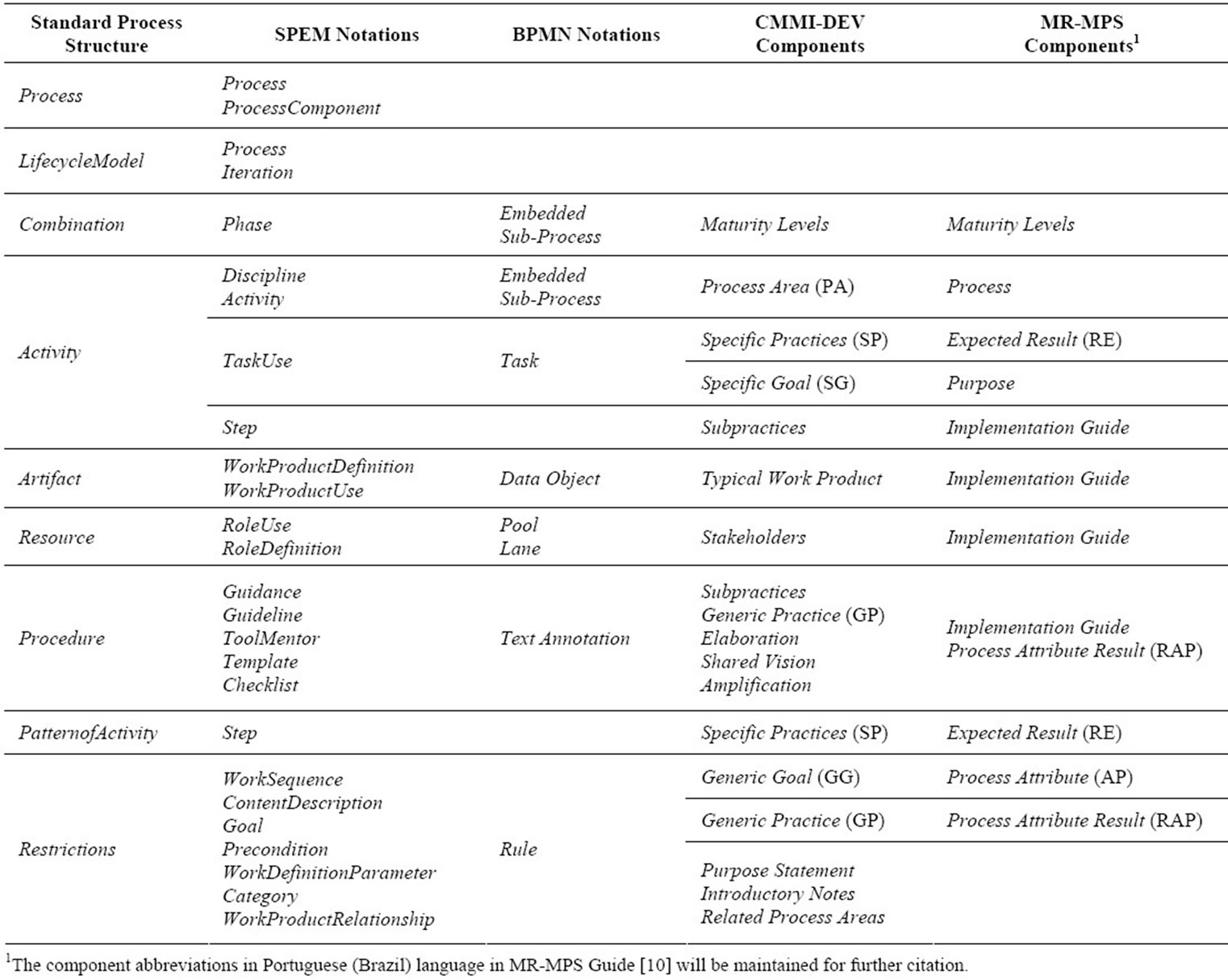
Table 1. Mapping between Standard Process Structure versus SPEM and BPMN notations versus CMMI-DEV and MR-MPS components.
cesses in general. This mapping is based upon: the Software Process Standard Structure presented in Subsection 3.1; the SPEM and BPMN notations; and the components of the CMMI-DEV and MR-MPS models.
The Process representation was mapped to two SPEM components, i.e. Process and ProcessComponent, that have a similar semantic that expresses a structured set of activities to perform a process. The BPMN has no specific notation to represent Process. It is represented by the process diagram instead. The CMMI-DEV and MRMPS models do not have any component equivalent to Process, because they suggest knowledge areas and best practices to define a software process.
The LifecycleModel can be represented in SPEM through the junction of the Process and Iteration components. Both describe the software life since its inception to its disuse. Furthermore, the Iteration specifies how this Process is organized. Both the CMMI-DEV and MR-MPS models do not specify a lifecycle in their models. These models only suggest that the lifecycle definition must be compliant with the nature and culture of the organization. Thus, each organization must define its own lifecycle.
The Combination component is represented in two SPEM components: Phase and ProcessPackage. Regarding BPMN, Combination is represented in Independent Sub-Process and Embedded Sub-Process. Phase is a significant period of time for a project that consists of interactions and milestones. ProcessPackage contains elements to define a process: activities, roles and products. An Independent Sub-Process can also include roles, activities and products in its definition. An Embedded Sub-Process represents any type of work performed in a process which is composed of other activities. The Combination regarding the CMMI-DEV and MR-MPS models is focused on Maturity Levels in composition of the Phase notation.
An Activity can be represented by Discipline in SPEM through a group’s practices adherent to a common theme. This concept is represented through the CMMI-DEV Process Area and it describes all the work performed to achieve the goal. Furthermore, regarding the MR-MPS model, it is represented through Process. A Process represents a set of goals related to an area considered important for this area improvement. A Discipline corresponds to an Embedded Sub-Process in BPMN.
A TaskUse in SPEM is equivalent to a Task in BPMN because both represent a task that cannot be further split into other tasks. A Task corresponds to Specific Goals and Specific Practices in CMMI-DEV because they respectively represent a goal of the process area used and a work fraction to be accomplished. Regarding the MRMPS, the Task corresponds to the Purposes and Expected Results which respectively represent the overall process implementation goal and activities that must be done to accomplish the Purpose. There is also the SPEM Activity notation which is related to the concepts of Purpose and Specific Goals of these models. Activity represents any type of work performed in a process. This process consists of other activities that are mapped to a BPMN Embedded Sub-Process which also can be composed of various activities. Regarding the CMMI-DEV and MRMPS, the Activity component is also respectively related to the Process Area and Process.
Regarding SPEM, a Step component is mapped to two concepts in the Standard Process Structure. It is mapped to Activity if this represents an ordered activity that aims to specify how a macro-activity can be performed. If it is the case, a Step relates to the CMMI-DEV Subpractices component because of the fact that it refers to an atomic activity. Step is partially mapped to the MR-MPS model because it does not have a Subpractices equivalent. Instead, the MR-MPS presents similar information to the Step in its Implementation Guide [10]. Step can also be mapped to the PatternOfActivities concept if it represents a collection of disordered activities that can be used as a guideline for the detection of sub-activities related to a macro-activity only if Step is associated with a method as a procedure. If this is the case, a Step relates instead to the CMMI-DEV Specific Goal and Specific Practice and the MR-MPS Expected Results. It is the case because the Expected Results incorporates practices and goals of an adopted process area.
An Artifact in the Standard Process is considered to be a SPEM WorkProductDefinition and a BPMN Data Object. An Artifact represents any product consumed or generated during the process. The CMMI-DEV component semantically equivalent to Artifact is the Typical Work Product. Furthermore, SPEM has a special component to represent an Artifact: a WorkProductUse that represents a task result which can be consumed or changed by another task. Regarding MR-MPS, the Implementation Guide contains references to artifacts that can be used as specific indicators of the implementation of the Expected Results.
A Procedure is represented by the Guidance component and the extensions of the later such as: Guideline, Template, Checklist and ToolMentor in SPEM; and Text Annotation in BPMN. A Text Annotation is a textual description that can also be linked to an Activity. Regarding CMMI-DEV, Procedures composes the Subpractices, Generic Practices Elaborations or Discipline Amplifications. It depends on the semantic description of these components. In MR-MPS, there are examples of Procedures in the Implementation Guide and in the Process Attribute Result as well. This information is presented in the Process Attribute Result because it aims to assist the institutionalization of the process.
The Resource is mapped to the SPEM RoleDefinition and RoleUse. It is justified because roles are necessary to carry out activities. A Resource is mapped to the BPMN Pool that represents a process participant and includes a series of Tasks; and Lanes that are subdivisions of a Pool. Resources are defined by Stakeholders, as describes the CMMI-DEV model. However, regarding the MR-MPS model, Resources are presented in the Implementation Guide but they only indicates the resource characteristics and they not describe the set of abilities and competencies required.
Restrictions are mapped to a set of SPEM components. These components specify classifications or define limitations to the other components. In the case of the BPMN mapping, Restrictions are represented by the Rule component which specifies certain conditions for the realizetion of an event. Regarding CMMI-DEV, the Restrictions can be represented by several components that limit and restrict the execution of activities in the Process Areas. Otherwise, the Restrictions relates to the MR-MPS Process Attributes and Process Attributes Results. These MR-MPS components determine the conditions for the process institutionalization in the organizations.
The mapping of these approaches can lead to the conclusion that the standard may increase the productivity and quality of the development processes. To that end, the Section 4 presents a case study that aims to present a more practical use of SPEM and BPMN process modeling standards following the recommendations of the CMMI-DEV and MR-MPS models. Moreover, the case study presented in the following section validates the mapping presented in this section.
4. Case Study: REQM and GRE Modeling
The case study reported in this section was based upon the mapping presented in [15], which contains guidelines for the implementation and evaluation of the Reference Model MR-MPS: 2009 in conjunction with the CMMIDEV v1.2. This mapping between the two models considered that the MR-MPS processes are related to the process areas of CMMI-DEV and the expected results of the MR-MPS processes are related to the specific practices of the process areas of CMMI-DEV.
From this premise, we chose to model the Requirements Management (REQM) Process Area of CMMIDEV, belonging to the Maturity Level 2 in their staged representation, with the Requirements Management (GRE) Process of MR-MPS, part of the Maturity Level G. Both will be jointly modeled in SPEM and BPMN standards, considering the equivalence between the components of quality models, in accordance to the mapping presented in Subsection 3.2 and the mapping between the expected results of the GRE process of MR-MPS and the specific practices of the area REQM process of CMMI-DEV, presented in [15].
4.1. Modeling in SPEM
The Figure 2 presents the modeling of components for the GRE process of MR-MPS, and REQM process area of CMMI-DEV in SPEM.
The REQM and GRE are considered in SPEM a Discipline classified in Phase of Maturity Level 2 and Level G. In this case study, we present the SG 1, which states that “requirements are managed and inconsistencies with project plans and work products are identified” [11]. In the MR-MPS, the corresponding component is the process Purpose, in which case is that GRE “manages product requirements and product components of the project and identifies inconsistencies between requirements, project plans and work products of the project” [10].
The SP 1.2 recommends to “Obtain commitment to requirements from project participants” which is equivalent to GRE 2, which in turn determines “The commitment of the technical staff with the approved requirements is obtained”. Both are represented by the SPEM Activity notation and are detailed in Figure 3.
According to the CMMI-DEV, the following artifacts (WorkProducts in SPEM) are used or produced:
• Requirements impact assessments;
• Documented commitments to requirements and requirements changes.
On the other hand, MR-MPS exemplifies (in its Implementation Guide-Level G) that the artifact Minutes of the Meeting can help the achievement of this expected result.
The Implementation Guide-Level G of the MR-MPS do not make any reference to sub-practices and procedures for this activity, while the CMMI-DEV specifies the following Sub-practices (Steps in SPEM) for this activity:
• Assess the impact of requirements on existing commitments;
• Negotiate and record commitments.
The extension to the Guide to Integrated Product and
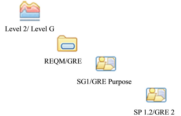
Figure 2. REQM and GRE structure in SPEM.
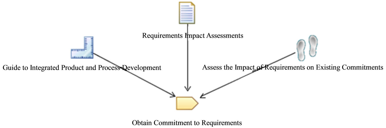
Figure 3. SP 1.2 and GRE 2 representation in SPEM.
Process Development in CMMI-DEV highlights the importance of the agreement of different teams participating in the project to the requirements. This is considered a Guidance in SPEM.
4.2. Modeling in BPMN
The Figure 4 presents the modeling of the components related to the GRE process of MR-MPS, and to the REQM process area of CMMI-DEV in BPMN.
The REQM and GRE are considered an Embedded Sub-Process in BPMN, corresponding to another SubProcess that represents the Maturity Level 2 and Level G, respectively. As in Subsection 4.1 we present the first SG 1 of CMMI-DEV and the GRE Process Purpose of MRMPS, now the components are represented by the BPMN Task component.
Both the SP 1.2 and the GRE 2 are represented by the Task notation in BPMN. These activities, as presented in Subsection 4.1, have: the Requirements Impact Assessments artifact, represented by the Data Object notation; the Guide to Integrated Product and Process Development procedure, represented by a Text Annotation, and the Assess the impact of requirements on existing commitments sub-practice. These details are presented in the model of Figure 5, except for Sub-practice, since this component does not have a correspondent notation in BPMN.
This case study provides a basis to perform the analysis of the representativeness of SPEM and BPMN standards in the context of software process modeling, presented in Section 5. Immediately, it can be seen that the SP 1.2 and GRE 2 are not equally represented in both modeling standards, which allows us to draw conclusions from a more detailed analysis.
5. Analysis of Representativeness
After presenting the case study and mapping it is possible to assess the representativeness of SPEM and BPMN standards. By establishing a comparison between these two standards, consider the following specific objective: to identify which of the two standards is more suitable for process modeling software. Thus, we identified some desirable features for performing this process modeling, using as a basis the recommendations found in [13]:
• Expressiveness: the capability of representing the complexity and all the assets of software processes, according to the elements of the Ontology defined in [14] and shown in Figure 1;
• Reuse: the ability to promote the reuse of assets contained in the process model;
• Management: management support of the instances of the process (planning, monitoring and control);
• Evolution: easiness to identify inefficient parts of the process, thereof aiming at improvement and development;
• Multilevel: ability to provide high level views of the process, as well as greatly detailed ones;
• Understanding: the capability to understand the model by all involved in the process, being the ones in the organization to which the process aims or their intended customers, especially those who are not experts in process modeling;
• Organizational Integration: ability to establish integration and interaction with processes in other areas of the organization, facilitating the definition of processes with overall organization objectives alignment.
In order to analyze the attendance of these characteristics by the SPEM and BPMN standards three criteria were established, as shown in Table 2.
The Table 3 shows the analysis between SPEM and BPMN considering desired characteristics, using previously set out criteria and thereof justifying, when required, the choice made.
It was performed a comparative analysis to evaluate the characteristics presented in Table 3. This analysis had the following results:
• Expressiveness: BPMN is not a notation focused on software process modeling. Therefore, BPMN has less expressiveness than SPEM. This was demonstrated in the case study presented in the Section 4. It
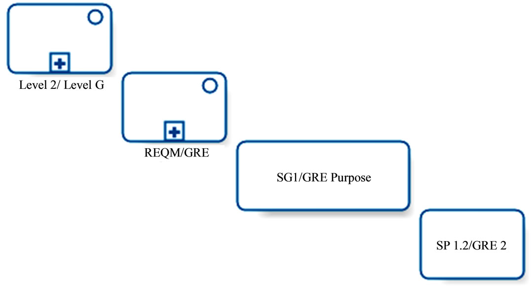
Figure 4. REQM and GRE structure in BPMN.
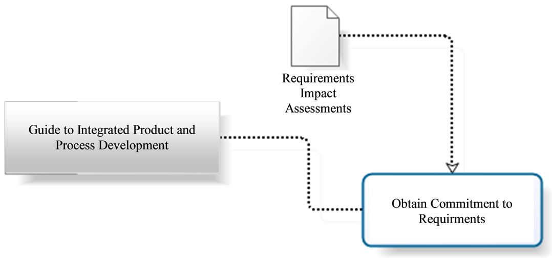
Figure 5. SP 1.2 and GRE 2 representation in BPMN.
was not possible to represent the specific Subpractices to run the activities (Figure 5) through the BPMN notation in the Case Study. However, the SPEM notation was able to achieve that through the Step component presented in the Figure 3;
• Reuse: both standards allow the reuse of the notations used to represent the process assets. In the case study, the Activity (Figure 2) and Task (Figure 4) components respectively of SPEM and BPMN were reused;
• Management: SPEM defines specialized notations to process instances because it is a software process modeling standard. Both Discipline and Phase are examples of this. Nevertheless, BPMN supports this through Embedded Sub-Process (Figure 4);
• Evolution: the evaluation and improvement of the process occur through the execution of it. This can help to identify weak points in the process through the analysis of the generated metrics. Regarding this, BPMN has the BPEL4WS execution language (Business Process Execution Language for Web Services). However, SPEM is not very clear about the support to the process enactment [1];
• Multilevel: both standards have appropriate notations to describe the processes in both high and low detail levels. However, the SPEM standard provides a greater number of concepts to express the multiple detail level, as evidenced with the presentation of the Process and Lifecycle notations (Table 1);
• Understanding: BPMN is a standard for modeling general business processes and aims to provide an understandable notation to all the process stake-holders. The objective of SPEM is to be a standard reference for software process modeling, using notations common to professionals in this area;
• Organizational Integration: the SPEM standard focuses basically on the software development area of the organization. Since BPMN standard is oriented to business processes modeling, it allows the integration of software process modeled in its notation with other business process models of an organization.
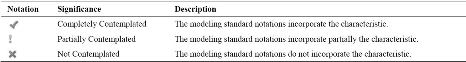
Table 2. Attendance criterias of evaluated characteristics.

Table 3. Analysis of SPEM and BPMN representativeness.
6. Final Thoughts
The objective of the comparative study presented in this paper is to bring the Software Engineering community useful information to guide the choice of a standard, from the analysis of the organizational context in which the process will be defined, including organizational culture, human resources characteristics, relations between the various areas of the company. We expect this information, together with the results obtained in this work, provides software developer organizations the support to choose which technology would be more appropriate in defining and shaping their development process.
Moreover, this paper made a comparison between the elements that compose the structure of CMMI and MPS.BR. Both models, being more focused on structural part of the process, lack representativeness in the modeling of processes with a higher degree of specification, where the SPEM has many components to represent this aspect. However, BPMN tends to be more easily understood and aims at the integration of organizational processes, it does not have as much expressiveness in the representation of software processes adhering to these models, based upon the study case.
This evaluation of modeling standards contributed to the conception of SPIDER_ML [16], a modeling language characterized as a profile of SPEM 2.0. The choice of relying on SPEM is due to the fact that this is the OMG standard for modeling software processes, and due to the goal of SPIDER_ML to incorporate and formalize the practice of process modeling used by the software industry using a reduced number of components when compared to the number of elements of SPEM [17,18]. This language is adopted in the tool Spider-PM in use at the SPIDER Project (acronym for Software Process Improvement: DEvelopment and Research) [19]. This project has the major focus of presenting technological solutions (open source tools, frameworks, toolsets) with appropriated characteristics to meet the best practice described in the quality models CMMI-DEV and MR-MPS.
The SPIDER_ML extension to support flexible and semi-automated process enactment is the scope of another study being currently in development [20]. Based upon the definition of enactment formalism, called xSPIDER_ML, the SPIDER_ML will fully contemplate the process evolution characteristic, in order to provide greater dissemination and understanding of the SPEM language.
7. Acknowledgements
The authors would like to thank CNPq (Conselho Nacional de Desenvolvimento Científico e Tecnológico—National Counsel of Technological and Scientific Development), for financial support through the DTI grant of the MCT/CNPq/FNDCT No. 19/2009 announcement for the development of this work.
REFERENCES
- R. Bendraou, B. Combemale, X. Crégut and M.-P. Gervais, “Definition of an Executable SPEM 2.0.,” In: 14th Asia-Pacific Software Engineering Conference, Aichi, 4-7 December 2007, pp. 390-397. doi:10.1109/ASPEC.2007.60
- B. Curtis, M. Kellner and J. Over, “Process Modeling. Communications of ACM,” ACM, Vol. 35, No. 9, 1992, pp. 75-90.
- J. Lomchamp, “A Structured Conceptual and Terminological Framework for Software Process Engineering,” The Second International Conference on the Software Process: Continuous Software Process Improvement, Berlin, 25-26 February 1993, pp. 41-53.
- W. Humphrey, “Managing the Software Process. The SEI Series in Software Engineering,” Addison-Wesley, Boston, 1989.
- M. Kellner and G. Hansen, “Software Process Modeling. Technical Report CMU/SEI-88-TR-009,” Carnegie Mellon University/Software Engineering Institute, Pittsburgh, 1988.
- OMG, “Software & Systems Process Engineering Meta-Model Specification,” 2008. http://www.omg.org/spec/SPEM/2.0/PDF
- OMG, “Business Process Model and Notation (BPMN),” 2011. http://www.omg.org/spec/BPMN/2.0/PDF
- OMG, “Object Management Group,” 1997. http://www.omg.org/
- S. Oliveira, A. Vasconcelos and R. Mendes, “Mapping of CMMI Guide Concepts on SPEM Notations from Software Process Definition Context,” Journal of Computer Science, Vol. 5, No. 4, 2006, pp. 83-92.
- SOFTEX, “MPS.BR: Guia Geral,” 2011. http://www.softex.br/mpsbr/_guias/guias/MPS.BR_Guia_Geral_2011.pdf
- SEI, “CMMI for Development,” 2010. http://www.sei.cmu.edu/reports/10tr033.pdf
- F. Zorzán and D. Riesco, “Transformation in QVT of Software Development Process based on SPEM to Workflows,” Journal Latin America Transactions, IEEE, Vol. 6, No. 7, 2008, pp. 655-660.
- J. Pérez, “Notaciones y Lenguajes de Procesos: Una Visión Global,” Ph.D. Research Report, University of Sevilla, Sevilla, 2007.
- G. Guizzardi, R. Falbo and R. Guizzardi, “Grounding Software Domain Ontologies in the Unified Foundational Ontology (UFO): The Case of the ODE Software Process Ontology,” In: XI Iberoamerican Workshop on Requirements Engineering and Software Environments, Recife, 2008.
- SOFTEX, “Guia de Implementação—Parte 11: Implementa- ção e Avaliação do MR-MPS: 2009 em Conjunto com o CMMI-DEV v1.2,” 2011. http://www.softex.br/mpsbr/_guias/guias/MPSBR_Guia_de_Implementa%C3%A7%C3%A3o_Parte_11.pdf
- SPIDER_ML, “Especificação Técnica,” 2009. http://www.spider.ufpa.br/projetos/spider_pm/SPIDER_ML%5B1.1%5D.pdf
- R. Barros and S. Oliveira, “SPIDER_ML: Uma Linguagem de Modelagem de Processos de Software,” II Escola Regional de Informática, Manaus, 2010.
- R. Barros and S. Oliveira, “Spider-PM: Uma Ferramenta de Apoio à Modelagem de Processos de Software,” VIII Encontro Anual de Computação, Catalão, 2010.
- S. Oliveira, et al., “SPIDER: Uma Proposta de Solução Sistêmica de um SUITE de Ferramentas de Software Livre de Apoio à Implementação do Modelo MPS.BR.” Revista do Programa Brasileiro da Qualidade e Produtividade em Software, 2nd Edition, 2011, pp. 103-107.
- C. Portela, A. Vasconcelos and S. Oliveira, “Spider-PE: Um Ferramental de Apoio à Execução de Processos Aderente a Modelos de Qualidade,” IX Workshop de Teses e Dissertações de Qualidade de Software, Curitiba, 2011.