Engineering
Vol.6 No.5(2014), Article ID:44536,6 pages DOI:10.4236/eng.2014.65029
Determine the Stress Calculating Mode of Sliding Failure of Soil Mass under the Push-Extend Multi-under-Reamed Pile
Yongmei Qian, Xuezhe Chen, Xuewen Xie
Jilin Jianzhu University, Changchun, China
Email: 654675316@qq.com, 614221789@qq.com, 953517776@qq.com
Copyright © 2014 by authors and Scientific Research Publishing Inc.
This work is licensed under the Creative Commons Attribution International License (CC BY).
http://creativecommons.org/licenses/by/4.0/


Received 27 November 2013; revised 27 December 2013; accepted 5 January 2014
ABSTRACT
Through the analysis of the sliding failure form of soil mass under the bearing push-extend reamed of Push-extend Multi-under-reamed Pile, in the paper, the law of coulomb-Mohr is used to establish a stress function and the theory of the sliding line is used to establish Prandtl regional stress field, which determines the stress calculating mode of soil mass and provides a theoretical basis for a further study of this type of pile ultimate bearing capacity of soil mass.
Keywords:The Push-Extend Multi-under-Reamed Pile; Sliding Failure; the Bearing Push-Extend Reamed; Calculating Mode

1. Introduction
The failure performance of the foundation is the slide of soil mass, when the soil mass is sliding, we can usually find the through sliding surface (or called slip line). So the strength of the soil mass is actually the relative sliding resistance between one part of the soil mass and the other, which is the shear strength, and essentially is the friction between soil mass and soil mass. So the shear strength of soil mass is in conformity with the law of friction. Because it is the friction of the same kind of material between different parts, in order to distinguish it from the friction between different materials, it is known as the internal friction, the corresponding coefficient called internal friction coefficient. According to the analysis of theory and the experimental research on the failure mechanism of pile soil of the Push-extend Multi-under-reamed Pile, the results show that the destruction of the soil mass under the plate also complies with the law above and belongs to the sliding failure, and that the ultimate bearing capacity of the soil mass can be solved by the theory of slip line. Therefore, this article uses the theory of slip line to determine conforms to the stress calculating mode of failure modes of soil under the Pushextend Multi-under-reamed Pile [1] .
2. The Law of Coulomb-Mohr
At present, the most successful failure theory is to use stress to define the failure, in soil mechanics, the soil mass shear failure is often based on the theory of coulomb—Mohr strength. This theory considers that if the shear stress of any section is equal to the shear strength of the material, then material appears failure. As shown in Figure 1, this figure paints the stress Mohr circle when material causes damage in the rule of coulomb, when the internal force on cross section and the corresponding Mohr circle inside the boundary, failure occurs. The failure surface of Mohr circle is usually called slip plane (or line), the acute angle that each other forms is 90˚ − φ, both failure on the cross section of normal stress σ and shearing strength τ meet the law of coulomb-Mohr, that is: τ= c – σtanφ [2] .
Symbolic rules: The symbols of normal stress and shear stress at any section of symbols, according to the custom(the right hand spiral rule), when the direction of rotation is clockwise, normal stress to tensile stress is positive, Shear stress to tensile stress and the order of shear stress satisfies the corkscrew rule is positive.
Significance of symbol: As shown in Figure 1, the intercept between failure envelope and vertical coordinates is c, which is called cohesive material (or cohesion). The slope angle of the failure envelope is called the angle of internal friction φ, φ is called the shear strength index of soil mass, and is an important mechanical indexes of soil mass.
3. The Establishment of Stress Function
As shown in Figure 1, the radius of the Mohr circle which is corresponded to the failure surface is
 , so:
, so:
 (1)
(1)
We get: 
That is: 
Let , then the above formula is:
 (2)
(2)
So
 (3)
(3)
Let
 , so
, so  (4)
(4)
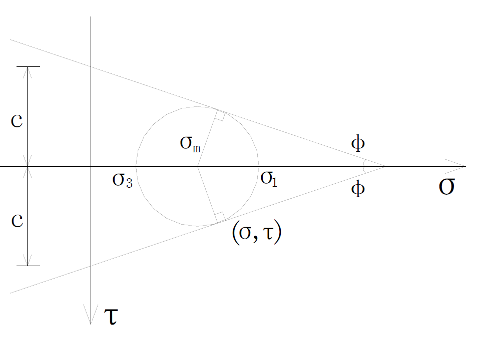
Figure 1. The stress Mohr circle when it is damaged.
According to the formula (3), we get:
 (5)
(5)
4. Coulomb Hypothesis
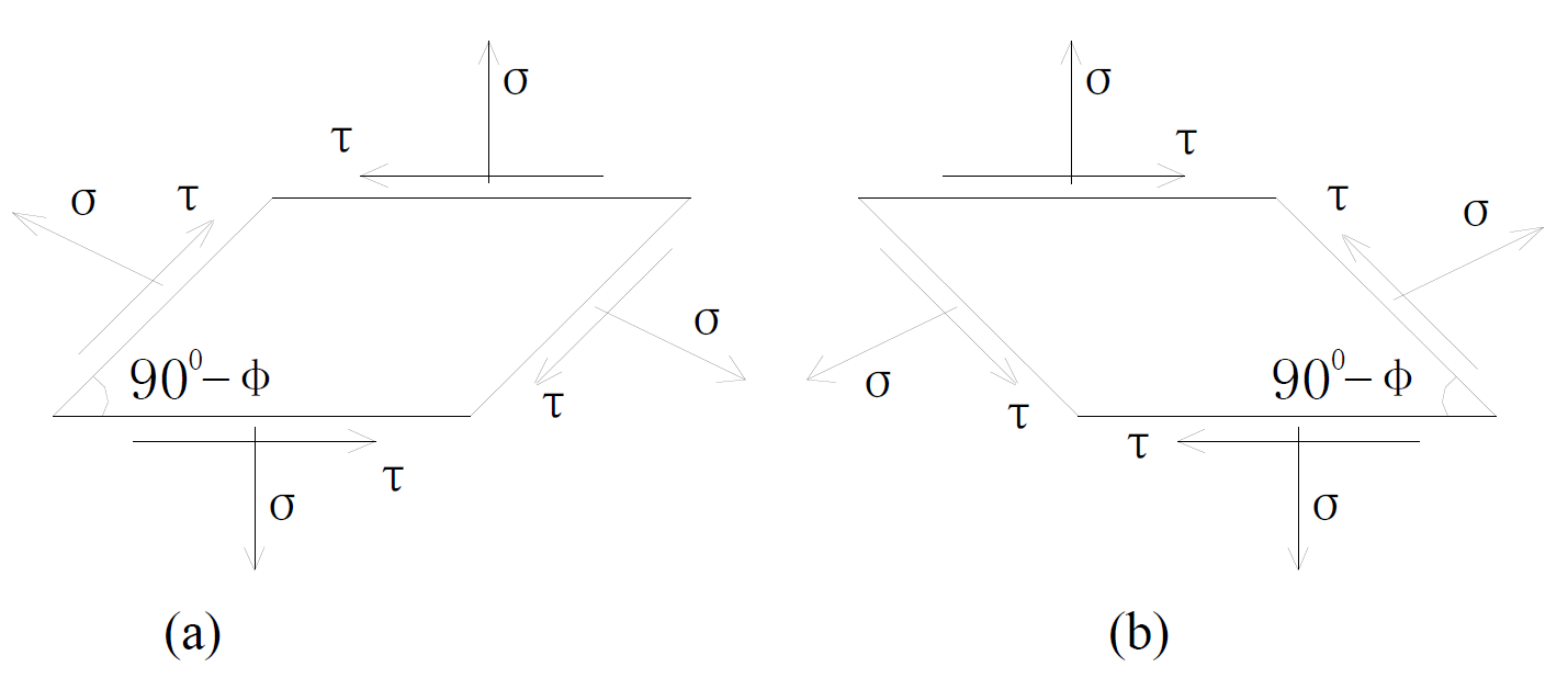
According to the law of Coulomb, in the stress field, on the failure surface where each other are in a 900 − φ acute angle, shear stress point to the opposite way to the intersection edges. As shown in Figure 2, a and b are two positive and negative failure surfaces respectively.
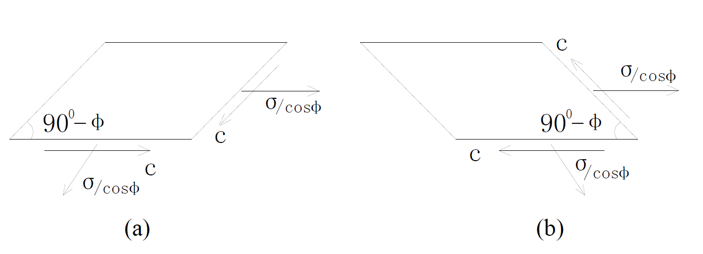
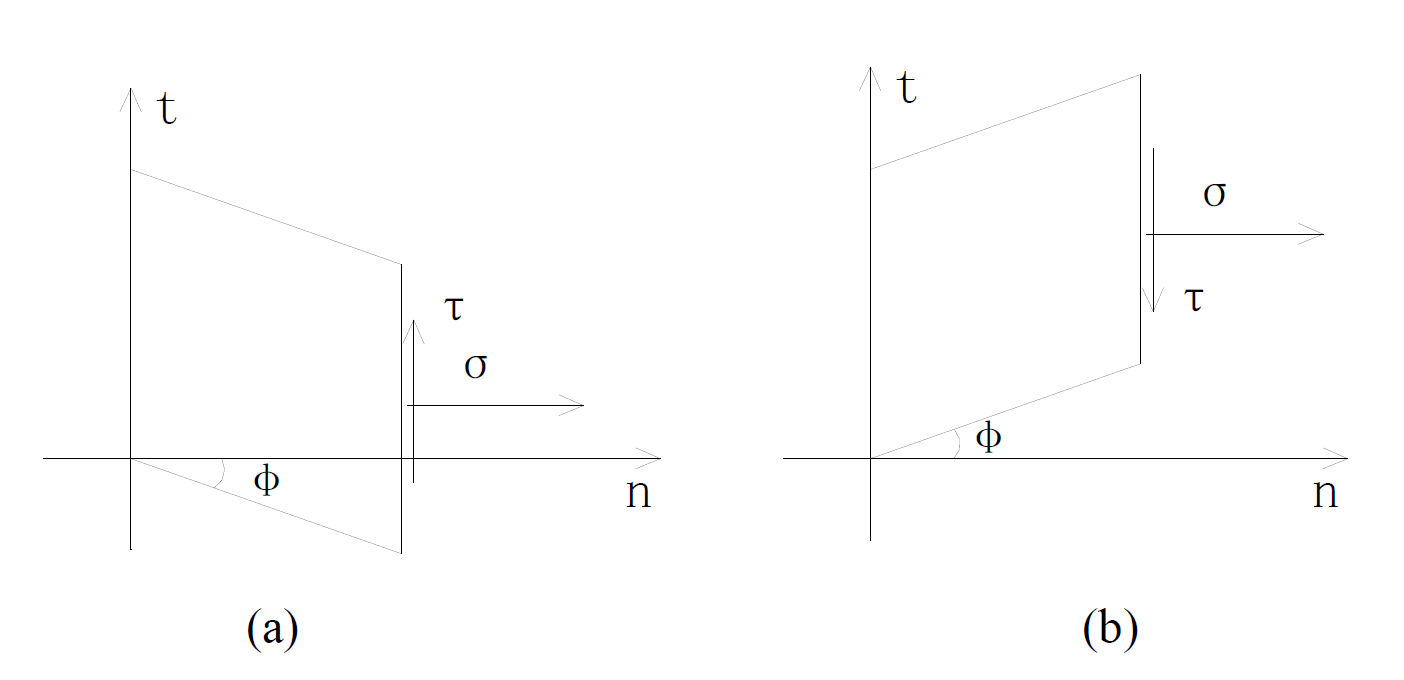
Explode stress to the stress on failure surface, as shown in Figure 3(a) and Figure 3(b) are two positive and negative failure surfaces. Make the failure surface t axis, use Cartesian coordinates (t, n) to show stress field, as shown in Figure 4, a and b are two positive and negative failure surfaces.
So the stress field is:
 (6) (positive)
 (7) (negative)
 (a) (b)
Figure 2. The stress pictures of two positive and negative failure surfaces.
 (a) (b)
Figure 3. The two positive and negative exploded views of failure surfaces.
 (a) (b)
Figure 4. Stress field under the cartesian coordinates.
If  is the average stress in the surface,
According to Mohr circle, we get
 (8)
(8)
 (9)
(9)
 (10)
(10)
5. The Satisfied Yield Condition in Failure Surface (Stress Condition)
In Mohr circle, the radius which is corresponded to the failure surface , can be expressed as
 , thus, we can calculate the stress on the arbitrary section. Supposed that the included angle between one surface and the failure surface is θ, and the stress on the surface are σX, σY, τXy.
As shown in Figure 5.
According to Mohr circle, we get:
 (11)
(11)
In the same way:
 (12)
(12)
 (13)
(13)
If the known stresses on arbitrary surface are ,
,  , for the location of failure surface and stress. In order to calculate easily, lead in β angle, as shown in Figure 5, take
  into formula (11) (13), we get:

Simplified as , get θ and stress on the failure surface:
 , according to formula (10), we get:
6. The Satisfied Equilibrium Condition on Failure Surface
At first, choose a simple damaged area which is statically admissible, according to failure form of soil mass
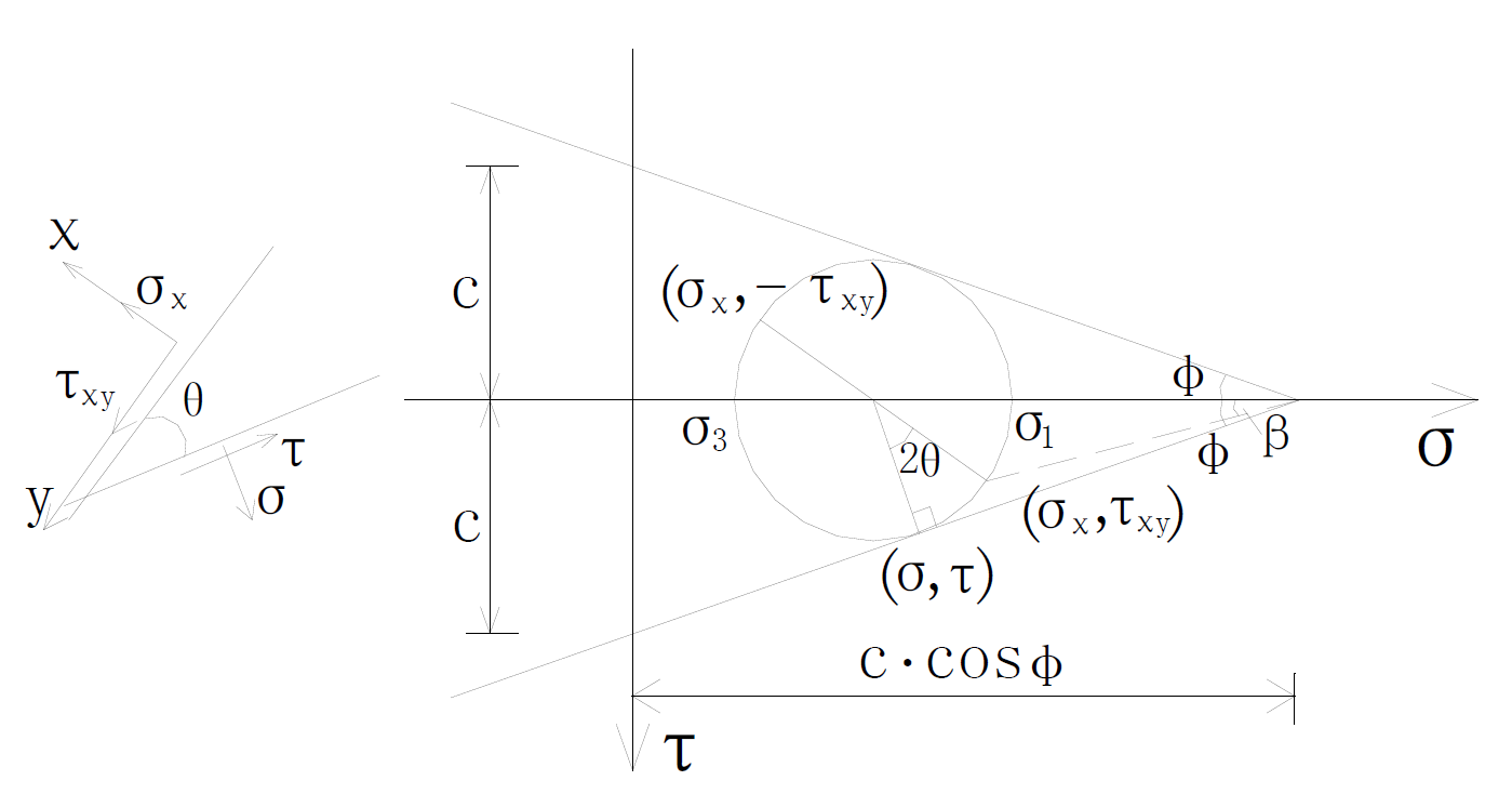
Figure 5. Stress picture on arbitrary surface in Mohr circle.
under the pile, choose Prandtl region. Take two sets of curves, one is logarithmic spiral line with inclination angle φ, the other is the polar rays, we can also get the 900-φ set of curves, as shown in Figure 6.
Coincide r axis and t axis which are in Figure 4, we get:
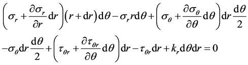
Establish polar coordinate and take the infinitesimal body, as shown in Figure 7, According to Figure 7, establish the equilibrium differential equation, due to , we get:
we get: 
In the same way, we get: 
Take formula (14) into equation, ignore the gravity,
 (15)
(15)
 (16)
(16)
Take tanφ × (16) + (15), we get: , explain that along the failure straight line, σ is a constant. According to formula (16), we get:
 .
.
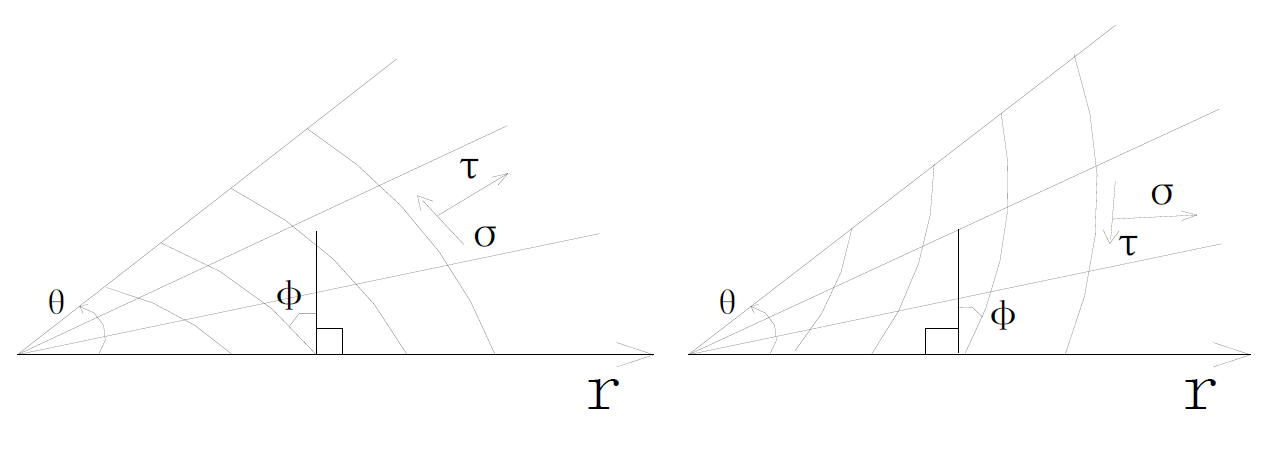
Figure 6. The stress field in prandtl regional.
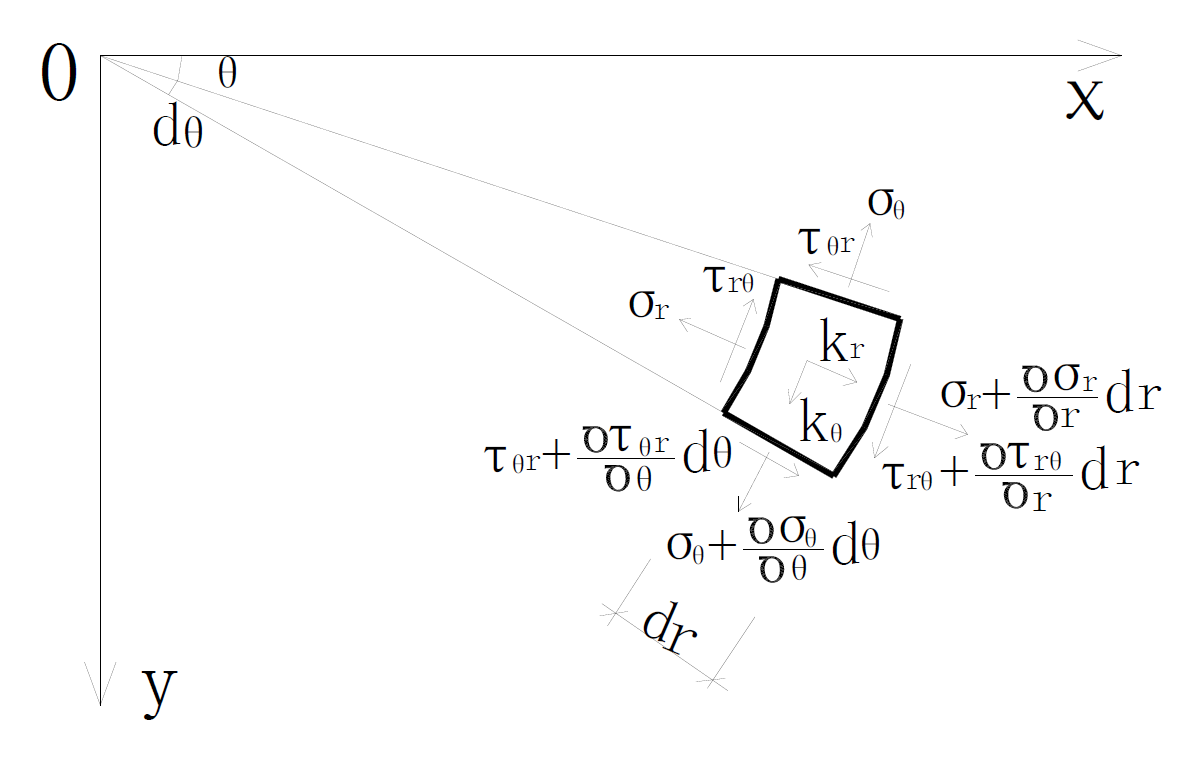
Figure 7. Stress diagram of the infinitesimal body under polar coordinate.
Then we get:
 (17)
(17)
Take (17) into (14), we get: 
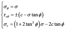
7. Conclusions
Because the failure form of the soil mass under the bearing push-extend reamed of Push-extend Multi-underreamed Pile belongs to the sliding failure, thus, the theory of the sliding line can be put in use to analysis the stress under the destruction of the soil mass. Through the analysis of the theory above, the law of CoulombMohr is used to establish a stress function, and according to the yield condition and equilibrium condition and so on, applying Prandtl regional stress field, determines the calculation model of the stress of the soil mass under the bearing push-extend Multi-under-reamed Pile.
Normal stress  shear stress
On the basis of the formula above, combining plastic potential theory and virtual work principle can determine ultimate bearing capacity of the soil mass under the push-extend Multi-under-reamed Pile, then can determine the calculation model of the bearing capacity of single pile further.
Acknowledgements
This work was financially supported by National Natural Science Foundation of China (51278224).
References
- Qian, Y.M., Wang, R.Z. and Yin, X.S. (2012) The Simulated Analysis in the Computer on the Effect of Pile and Soil Working Together about the Push-Extend Multi-under-Reamed Pile. Advanced Material Research, 479-481, 59-64.
- Qian, Y.M., Wang, R.Z. and Yin, X.S. (2011) Testing Study on the Shape of the Bearing Push-extend Reamed Affecting the Bearing Capability of the Pile. Architecture Technology, 42, 143-145. (in Chinese)