Engineering
Vol. 4 No. 9 (2012) , Article ID: 23227 , 4 pages DOI:10.4236/eng.2012.49069
The Vibration of Partially Filled Cylindrical Tank Subjected to Variable Acceleration
Mechanical Engineering Department, Faculty of Engineering Technology, Balqaa Applied University, Amman, Jordan
Email: *mohamed_gaith@yahoo.com
Received June 25, 2012; revised July 23, 2012; accepted August 1, 2012
Keywords: Moving Tanks; Sloshing; Natural Frequencies; Dynamic Response; Variable Moment of Inertia
ABSTRACT
In this study, the vibration of a cylindrical tank partially filled with liquid under motion modeled as mass lumped is investigated. A three-dimensional quasi-static model of a partially-filled tank of circular cross-section is developed and integrated into a comprehensive three-dimensional vehicle model to study its dynamic performance as a function of acceleration, and the fill volume. The liquid load movement occurring in the roll and pitch planes of the tank is derived as a function of the longitudinal acceleration, and then the corresponding shifted load is expressed in terms of center of mass coordinates and mass moments of inertia of the liquid bulk, assuming negligible influence of fundamental slosh frequency and viscous effects. The vibration characteristics of the partially filled tank vehicle are evaluated in terms of load shift, forces and moments induced by the cargo movement, and dynamic load transfer in the longitudinal direction. The semi analytical response is obtained by means of SimuLink™ Matlab Software. The effects of longitudinal aceleration of the tank system on the liquid surface inclination and consequently shifting of centroids and moment of inertia are illustrated.
1. Introduction
Sloshing is the low frequency oscillations of the free surface of a liquid in a partially filled container. This phenomenon in a moving tank is an important field of the fluid—structure dynamic research. The dynamic response of structures holding the liquid can be significantly influenced with these oscillations, and their interaction with the sloshing liquid may lead to instabilities as in many engineering applications, such as ground storage, marine transport of liquid cargo, aerospace vehicles, earthquake-safe structures and liquid moving tanks. Due to its dynamic nature, sloshing can strongly affect the performance and behavior of transportation vehicles, especially tankers filled with oil. Furthermore, seismic design of liquid storage tanks requires knowledge of sloshing frequency of liquid and hydrodynamic pressure on the wall. The corresponding hydrodynamic seismic forces can be obtained using the frequency of sloshing, [1].
Vibration analyses of fluid-structure interaction problems have gained much attention with various aspects and approaches proposed for giving solutions to instability behavior. Veletsos and Yang [2,3] presented solutions for the dynamic pressure and the impulsive mass under the assumption of certain deformation patterns of the tank wall. When liquid mass represents a large percentage of the total mass of a structure, sloshing could induce disturbance to its stability. This is mainly contributed to by the induced dynamic loads and shift of the centre of gravity. Therefore, the liquid-tank system was treated as an equivalent mechanical spring-mass system [4-6]. Rammerstorfer et al. [7] obtained the vibration mode shape of the container shell wall by using an iterative procedure which starts by adopting an initial guess of the mode shape. Welt and Modi [8] showed that sloshing resulting from external forces is critical when the excitation frequency is close to the fundamental sloshing frequency. Jain and Medhekar [9,10] studied this mechanical model with different models for rigid and flexible tanks. Chen and Haroun [11] obtained the natural frequencies and mode shapes of standstill flexible containers with liquid. Takahara et al. [12] simulated sloshing of fluid in cylindrical tanks subjected to pitching excitation at a frequency in the neighborhood of the lowest resonant frequency. Kyeong and Seong [13] studied the free vibration of either a partially liquid-filled or a partially liquid-surrounded circular cylindrical shell with various classical boundary conditions. In their study, the liquid-shell coupled system was divided into two regions. One region is the empty shell part in which Sanders’ shell equations are formulated without the liquid effect. The other is the wetted shell region in which the shell equations are formulated with consideration of the liquid dynamic effect. The same authors [14] later extended the study to the hydroelastic vibration of partially liquidfilled cylindrical containers with arbitrary boundary conditions. It was found that the variation of the natural frequencies depends on the axial mode number and circumferential wave number. Chang and Chiou [15] obtained the natural frequencies of clamped-clamped laminated cylindrical shells conveying fluid by using Hamilton’s principle. Anderson [16] studied the container flexibility as a control of liquid sloshing. Numerical and experimental results showed that the sloshing wave amplitude can be significantly reduced by tuning the interaction of the flexible container with liquid sloshing. Garrido [17] studied the effect of sloshing in a rectangular container which is first accelerated, and then decelerated due to frictional forces using pendulum model.
Several methods were used to analyze the partially filled tank system. To and Wang [18] and Subhash and Bhattacharyya [19] employed the finite element method (FEM) that made use of two-node thin elastic shell and eight-node fluid elements for the coupled vibration analysis of the liquid-filled cylindrical containers. Amabili [20] employed the Rayleigh-Ritz method to study the vibration of simply supported, circular cylindrical shells that are partially-filled with an incompressible sloshing liquid. The Rayleigh quotient is transformed into a simpler expression where the potential energies of the compressible fluid and free surface waves do not appear. Wang and Khao [21] used a finite element method to study sloshing in a two dimensional rectangular container subjected to random excitation. The method is based on fully nonlinear wave potentional theory based on the finite element method. Vamsi and Ganesan [22] presented a semi-analytical finite element approach to discretise the shell structure in cylindrical containers filled with fluid. The fluid velocity potential was approximated by polynomial functions instead of Bessel functions. The study was carried out for both elastic and viscoelastic shells. The natural frequencies of the system obtained by the polynomial approach compared very well with other results using numerical methods. They concluded that the polynomial approach would be more elegant and general than the Bessel function approach since in the later approach, Bessel function values have to be evaluated depending on shell dimensions. Thus, very few attempts were carried out to analyze the system analytically. Jeong and Kim [23] obtained an analytical method for determining the natural frequency of shells filled with liquid. In this study, the liquid was constrained to move through rigid plates placed at the top and bottom of the shell.
Sloshing may cause large internal forces and deformation in the tank walls, particularly when the external forcing frequencies are close to the natural sloshing frequencies. Tank walls may therefore be damaged arising from high fluid dynamic pressures as a result of resonance. A significant example of area where the effect of sloshing is of concern is in the transportation of various types of liquid in moving tanks. Strandberg [24] conducted experimental investigations to measure the liquid inclination force in longitudinal oscillated model tank. The effect of liquid forces on overturning and skidding Tendencies was evaluated from simplified tanker vehicle. Ranganathan [25] studied the directional stability of a tank vehicle and concluded that the directional response characteristics of a tank vehicle are affected by the liquid load shift of the fluid. He investigated directional response characteristics of partially filled tank vehicles during a given steering maneuver by utilizing an equivalent pendulum model. Rakheja et al. [26] conducted a field test of a two-axle truck with a tank body under a lane change maneuver and constant radius turn. Popov et al. [1] studied dynamics of liquid vibration in sinusoidal road containers under variable acceleration.
The objective of this paper is to determine the vibrational behavior of a liquid sloshing including the mode natural frequencies in three dimensional cylindrical moving tanks. In particular, a mechanical spring damper model to address the coupled liquid-tank interaction problem will be developed and used to study the effects of liquid sloshing on the structural response of the tank walls and the stability of the tank. The mode inherent frequencies will be deduced and the response will be obtained analytically by means of SimuLink™ Matlab Software. The analysis will reveal the effect of accelerations on liquid inclination and on the system vibration of cylindrical tank.
2. Problem Statement
Dynamic behavior and structure integrity of heavy commercial vehicles carrying liquid cargo on the highways are greatly influenced by the moving cargo within the partially filled tank. Liquid vibration in tank containers has received considerable attention in transportation engineering in the last two decades. Figure 1 shows the mechanical system considered in this study. The system consists of the mass M which represents the vehicle body and engine called sprung mass with tank length L and diameter D = 2R, its center of gravity changes based on the acceleration  subjected to the system, the masses
  and
and  which represent axles, suspension and tire masses, springs stiffness
  and damping coefficients
  are shown in Figure 1. The system is excited by a base excitation harmonic displacement
  and the harmonic excitation displacement frequency
  is a function of time,
  , due
, due

Figure 1. Mechanical model of the system.
to the acceleration, i.e., the base excitation frequency is not constant and is changing with time during the system motion.
2.1. Patterns of Surface Inclinations
Figure 2 shows different patterns or modes of liquid surface inclination subjected to longitudinal acceleration. Pattern 1 occurs under medium fill volume and acceleration while pattern 2 and 4 may occur in case of low and high fill volumes, respectively. Pattern 3 corresponds to medium fill condition at high acceleration. In this study, a complete analysis for pattern 1 will be performed and the other patterns can be treated in a similar manner with minor changes.
For pattern 1, the open tank liquid shown in figure 3 is accelerating to the right, the longitudinal direction, at a rate of . For this pattern to occur a net force must act on the liquid which is accomplished when the liquid redistributes itself as shown by
 . Under this condition the hydrostatic force at the left end is greater than the hydrostatic force at the right end, which is consistent with Newton’s second law. Furthermore, the quantitative analysis of the acceleration of the tank of liquid is characterized by using Bernoulli’s equation:
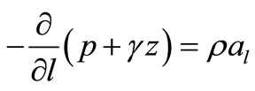 (1)
(1)
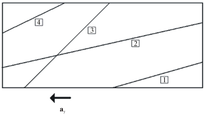
Figure 2. Patterns of surface inclination due to longitudinal acceleration.

Figure 3. The inclined angle for open tank liquid.
where the pressure along the liquid surface  is constant p = patm, and consequently
 . The acceleration along
  is given by
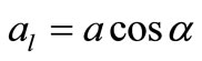 . Hence Equation (1) is reduced to:
 (2)
(2)
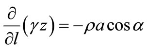
The total derivative is used since the variables do not change with time; the specific weight in Equation (2) is constant, and therefore, it becomes:
 (3)
(3)
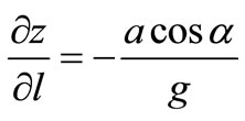
But 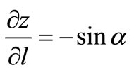 thus
thus
 (4)
(4)
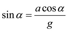
Hence, the inclination angle  can be determined from:
 (5)
(5)
Equation (5) describes the inclination angle of the liquid surface at the existence of acceleration.
Clearly, the liquid surface inclination angle,  , is directly proportional to the acceleration value.
2.2. Shifted Liquid Centroid and Moment of Inertia
To perform a complete analysis for the system, the centroid and the moment of inertia of the liquid mass must be defined since the two values change with the value of longitudinal acceleration. The approach used in this study to find centroid and the moment of inertia of the liquid mass is for the case considered (pattern 1) and other patterns can be treated similarly. Figure 4 shows a cylindrical partially filled tank of length L and circular cross section of radius R. The liquid of height R is exposed to acceleration so that the liquid will incline with angle  based on fluid mechanics principles presented earlier, and this will move the center of gravity of the liquid bulk to a direction opposite to
  direction for a distance corresponds to the angle
 .
.
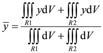
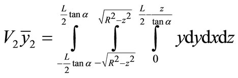
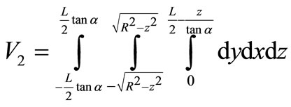
Figure 5 shows a 3D sketch of the deflected liquid bulk according to pattern 1. To find the centre of mass  (in y direction) and
  (in z direction) of the deflected liquid bulk, the triple integral over a certain region or regions can be used, and the equation of plane MNOP can be written as:
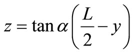 (6)
(6)
where the value of  and
and  can be obtained from the following formulas, respectively:
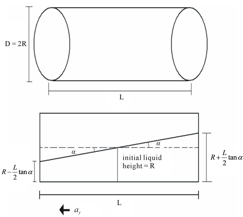
Figure 4. Partially filled moving tank model under acceleration.
 (7)
(7)
 (8)
(8)
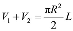
R1 is a symmetrical region without inclination and R2 with inclined liquid level as shown in figures 6 and 7.
Hence, for the system considered the value of  and
and  can be obtained from Equations (9) and (10), respectively.
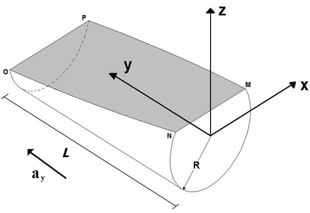
Figure 5. A 3D sketch of the deflected liquid.
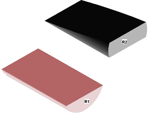
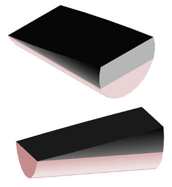
Figure 6. Integration regions R1 and R2.
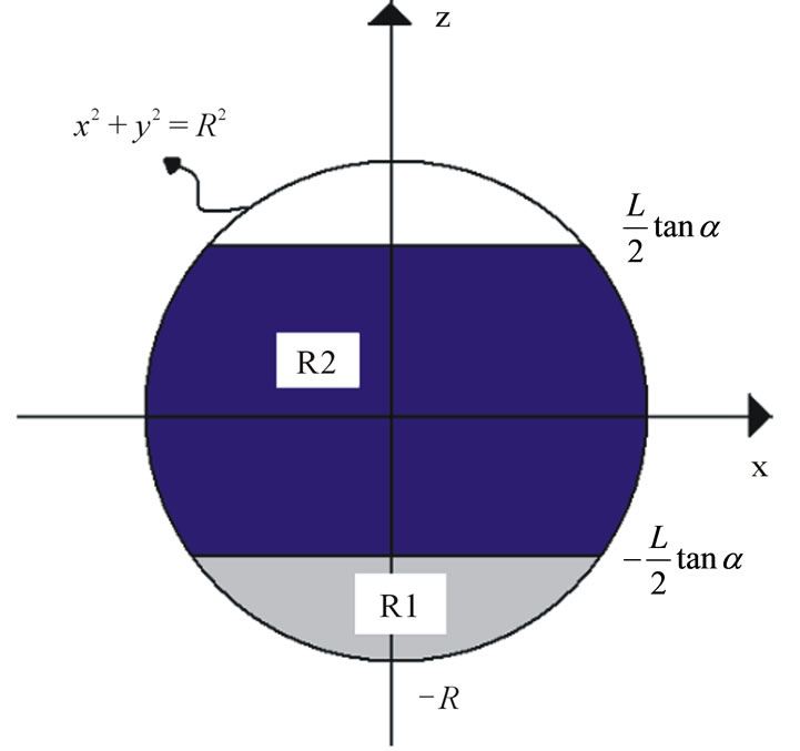
Figure 7. Combined R1 & R2 regions.
 (9)
(9)
 (10)
(10)
where
 (11)
(11)
 (12)
(12)
 (13)
(13)
 (14)
(14)
 (15)
(15)
 (16)
(16)
 (17)
(17)
The liquid bulk the moment of inertia  is evaluated by triple integral over the regions discussed earlier based on the following equations keeping in mind that this value is evaluated around the x-axis which is at a distance equals
  from the position of center of gravity.
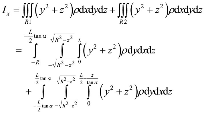 (18)
(18)
where  the density of the liquid (1000 kg/m3) for water). Using the parallel axis theorem, the shifted moment of inertia is written as:
 (19)
(19)
2.3. The Mechanical Vibration System
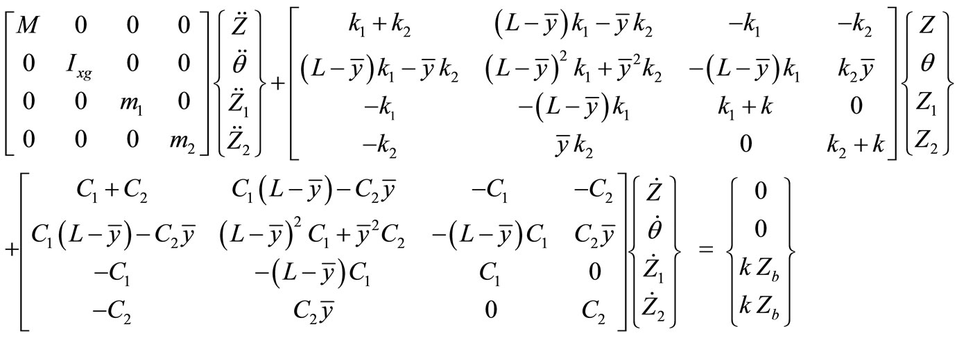
As shown in Figure 1, the vehicle is modeled with four degrees of freedom, namely, 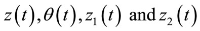 , the vertical displacement of the tank, rotational displacement of the tank, and the front and rear wheels of the vehicle, respectively. Hence, four governing vibration equations of motion for the system are written in matrix form as:
3. Results and Discussion
The effect of acceleration on  is illustrated in Figures 8-10, respectively. The input parameters used for a partially filled cylindrical moving tank are
 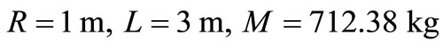 (with volume V = 4.712 m3, Semi-filled). Figure 8 shows the relationship between the inclined angles of liquid surface with applied acceleration value. Apparently, the higher the longitudinal acceleration the larger the inclination angle of the liquid surface. Figures 9 and 10 show an opposite behavior where the centroids and mass moment of inertia of the system, respectively, are decreasing, corresponding to the decrease of resistance against rotation, as the longitudinal acceleration increasing.
The vibration system of partially filled liquid moving tank is modeled and the governing equations are written in a matrix form. This nonlinear system is simulated using MatLab simulink to find the time responses. The input parameters used in this study are listed in Table 1, and the natural frequencies for the system are found as:
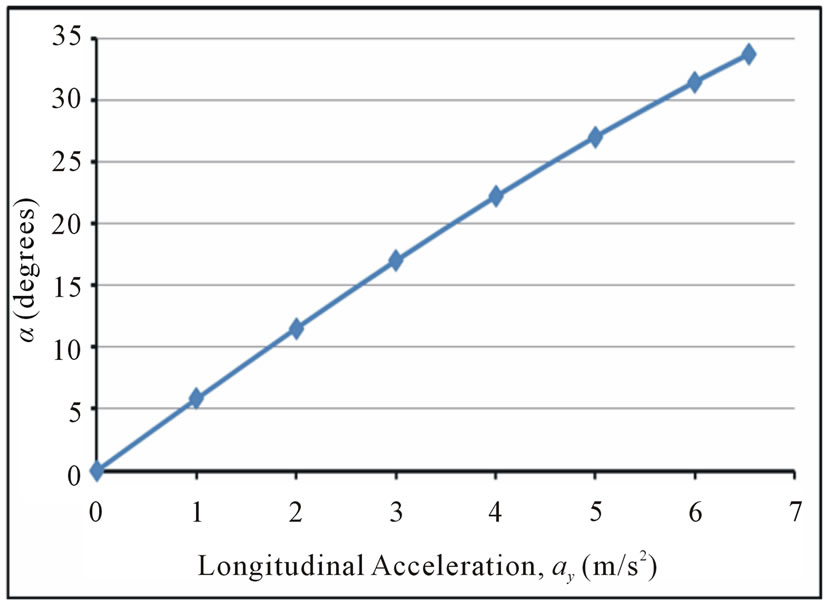
Figure 8. The liquid surface inclination angle versus the longitudinal acceleration of the vehicle.

Figure 9. The variation of the two varying centroids as a function of the longitudinal acceleration of the vehicle.

Figure 10. The variation of the mass moment of inertia as a function of the longitudinal acceleration of the vehicle.

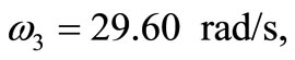

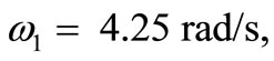 . The dynamic response is shown in figures 11-14. These figures show the dynamic response of the tank, z, θ, z1, and z2. The figures show clearly the transient behavior characterized with high amplitude which it may lead to tank accident and the vibration decays with time due to damping.
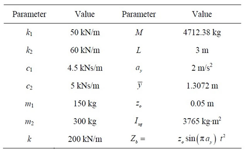
Table 1. The input parameters used for the system.

Figure 11. The lateral displacement of the tank, Z response versus time t.

Figure 12. The rotational displacement θ response versus time t.
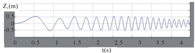
Figure 13. The front wheel displacement, z1 versus time t.
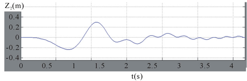
Figure 14. The rear while displacement z2 versus time t.
Notice that , where
  is the velocity in y direction and
 , where
  is the initial velocity. Assuming zero initial velocity,
 . Then for T = 2 m, the harmonic base excitation can be written as
 .
.
4. Conclusion
In this study, the vibration of cylindrical moving tank partially filled with liquid is modeled as mass lumped. A three-dimensional quasi-static model of a partially-filled tank of circular cross-section is developed and integrated into a comprehensive three-dimensional vehicle model to study its dynamic performance as a function of acceleration, and the fill volume. The liquid load movement occurring in the roll and pitch planes of the tank is derived as a function of the longitudinal acceleration, and then the corresponding shifting load is expressed in terms of center of mass coordinates and mass moments of inertia of the liquid bulk, assuming negligible influence of fundamental slosh frequency and viscous effects. The vibration characteristics of the partially filled tank vehicle are evaluated in terms of load shift, forces and moments induced by the cargo movement, and dynamic load transfer in the longitudinal direction. The results showed that cargo acceleration is directly proportional to the inclination angle of the liquid surface in a partially filled moving tank. The moment of inertia and center of gravity of the system are obtained and shown to be shifting to the opposite side of longitudinal acceleration direction. The inertia is decreasing when acceleration is increasing. The dynamic response of the system was obtained and showed a significant critical transient behavior with large amplitude, and the displacements are decaying after that due to the existing damping in the system.
REFERENCES
- G. Popov, S. Sankar, T. S. Sankar and G. H. Vatistas, “Liquid Sloshing in Rectangular Road Containers,” Computers in Fluids, Vol. 21, No. 4, 1992, pp. 551-569. doi:10.1016/0045-7930(92)90006-H
- A. S. Veletsos and J. Y. Yang, “Dynamics of Fixed Base Liquid Storage Tanks,” Proceedings of US-Japan Seminar on Earthquake Engineering Research with Emphasis on Lifeline Systems, Japan Society for Promotion of Earthquake Engineering, Tokyo, 8-12 November 1976, pp. 317-341.
- A. S. Veletsos and J. Y. Yang, “Earthquake Response of Liquid Storage Tanks,” Advances in Civil Engineering through Engineering Mechanics, ASCE, Raleigh, 23-25 May 1977, pp. 1-24.
- M. A. Haroun and G. W. Housner, “Seismic Design of Liquid Storage Tanks,” Journal of Technical Councils of ASCE, Vol. 107, No. 1, 1981, pp. 191-207.
- M. A. Haroun and G. W. Housner, “Earthquake Response of Deformable Liquid Storage Tanks,” Journal of Applied Mechanics, Vol. 48, No. 2, 1981, pp. 411-418. doi:10.1115/1.3157631
- A. S. Veletsos, “Seismic Effects in Flexible Liquid Storage Tanks,” Proceedings of the International Association for Earthquake Engineering Fifth World Conference, Rome, 25-29 June 1974, pp. 630-639.
- F. G. Rammerstorfer, K. Scharf, F. D. Fischer and R. Seeber, “Collapse of Earthquake Excited Tanks,” Journal of Mechanical Research, Vol. 25, No. 2, 1988, pp. 129- 143.
- F. Welt and V. J. Modi, “Vibration Damping through Liquid Sloshing, Part 1: A Nonlinear Analyses,” Transactions of the ASME, Journal Vibration and Acoustics, Vol. 114, No. 1, 1992, pp. 10-16. doi:10.1115/1.2930223
- S. K. Jain and P. S. Medhekar, “Proposed Provisions for a Seismic Design of Liquid Storage Tanks: Part I—Codal Provisions,” Journal of Structural Engineering, Vol. 20, No. 3, 1993, pp. 119-128.
- S. K. Jain and P. S. Medhekar, “Proposed Provisions for A Seismic Design of Liquid Storage Tanks: Part II— Commentary and Examples,” Journal of Structural Engineering, Vol. 20, No. 4, 1993, pp. 167-175.
- W. Chen and M. A. Haroun, “Dynamic Coupling between Flexible Tanks and Seismically Induced Nonlinear Liquid Sloshing,” Fluid Transients ASME, FED, Vol. 291, 1994.
- H. Takahara, K. Kimura and M. Sakata, “Frequency Response of Sloshing in a Circular Cylindrical Tank Subjected to Pitching Excitation,” Proceedings of Asia Pacific Vibration Conference, Kuala Lumpur, 27 November-1 December 1995, pp. 703-708.
- H. J. Kyeong and C. L. Seong, “Fourier Series Expansion Method for Free Vibration Analysis of Either a Partially Liquid-Filled or a Partially Liquid-Surrounded Circular Cylindrical Shell,” Computers & Structures, Vol. 58, No. 5, 1995, pp. 931-946.
- H. J. Kyeong and C. L. Seong, “Hydroelastic Vibration of a Liquid-Filled Circular Cylindrical Shell,” Computers & Structures, Vol. 66, No. 2-3, 1998, pp. 173-185. doi:10.1016/S0045-7949(97)00086-2
- J. S. Chang and W. J. Chiou, “Natural Frequencies and Critical Velocities of Fixed-Fixed Laminated Circular Cylindrical Shells Conveying Fluids,” Computer & Structures, Vol. 57, No. 5, 1995, pp. 929-939. doi:10.1016/0045-7949(94)00352-4
- J. G. Anderson, “Liquid Sloshing in Containers, Its Utilization and Control,” Ph.D. Thesis, Victoria University, Melbourne, 2000.
- M. F. Garrido, “On the Sloshing of Liquids in Parallelepiped—Shaped Containers,” European Journal of Physics, Vol. 24, No. 3, 2003, pp. 277-288.
- C. W. S. To and B. Wang, “An Axisymmetric Thin Shell Finite Element for Vibration Analysis,” Computers & Structures, Vol. 40, No. 3, 1991, pp. 555-568. doi:10.1016/0045-7949(91)90226-C
- B. S. Subhash and S. K. Bhattacharyya, “Finite Element Analysis of Fluid-Structure Interaction Effect on Liquid Retaining Structures Due to Sloshing,” Computers & Structures, Vol. 59, No. 6, 1996, pp. 1165-1171. doi:10.1016/0045-7949(95)00271-5
- M. Amabili, “Eigenvalue Problems for Vibrating Structures Coupled with Quiescent Fluids with Free Surface,” Journal of Sound and Vibration, Vol. 231, No. 1, 2000, pp. 79-97. doi:10.1006/jsvi.1999.2678
- C. Z. Wang and B. C. Khao, “Finite Element Analyses of Two-Dimensional Nonlinear Problem in Random Excitations,” Ocean Engineering, Vol. 32, No. 2, 2004, pp. 107- 113. doi:10.1016/j.oceaneng.2004.08.001
- K. B. Vamsi and N. Ganesan, “Polynomial Approach for Calculating Added Mass for Fluid-Filled Cylindrical Shells,” Journal of Sound and Vibration, Vol. 291, No. 3-5, 2006, pp. 1221-1228. doi:10.1016/j.jsv.2005.06.031
- K. H. Jeong and K. J. Kim, “Free Vibration of a Circular Cylindrical Shell Filled with Bounded Compressible Fluid,” Journal of Sound and Vibration, Vol. 217, No. 2, 1998, pp. 197-221. doi:10.1006/jsvi.1998.1741
- S. Strandberg, “The Effect of Inclined Force on Moving Tank,” Strandberg Engineering Laboratories, Inc. Greensboro, 2005.
- R. Ranganathan, “Analysis of Fluid in Partially Filled Tanks and Their Impact on the Directional Response of Tank Vehicles,” SAE, 1993, Article ID: 932942.
- S. Rakheja, R. Ranganathan and S. Sankar, “Field Testing and Validation of a Directional Dynamics Model of a Tank Truck,” International Journal of Vehicle Design, Vol. 13, No. 3, 1992, pp. 251-275.
NOTES
*Corresponding author.