Engineering
Vol.5 No.2(2013), Article ID:27731,5 pages DOI:10.4236/eng.2013.52027
Increase Ultrasonics Cleaning Efficiency of Electronics Modules
1Department of Electronic Technique and Technology, Belarus State University of Informatics and Radioelectronics, Minsk, Belarus
2Scientific-Engineering Enterprise “Optical Machine-Tool Building and Vacuum Plants”, Minsk, Belarus
Email: vlanin@bsuir.by, os_vt@mail.belpak.by
Received October 27, 2012; revised December 7, 2012; accepted December 22, 2012
Keywords: Ultrasonics; Cleaning; Electronics Modules; Cavitation Fields
ABSTRACT
The new approach is offered for the cleaning applications of electronics modules. The modular systems of the distributed ultrasonics converters, which are established in chessboard order, provide the uniformity cavitation fields in ultrasonic bath. The effect of periodic deviation of ultrasonics frequency created the directed acoustic currents in the liquid, witch increase removal pollution process. The technological parameters of automated ultrasonics cleaning lines as concentration SAS, temperature of washing solutions, and ultrasonics cavitation power are optimized.
1. Introduction
Cleaning of electronic modules after the soldering is the final operation responsible for completeness of all pollution removal after printed-circuit boards manufacture, storage, assembly and the soldering. Therefore cleaning should delete all pollution types: salts of the electrolytes, poisoning solutions, fluxes activators, fatty prints of fingers, a dust, and abrasive particles [1].
Poor-quality cleaning of products by their manufacture or storage causes decrease isolation resistance and physical destruction of conductors as a result of corrosion. Products of corrosion can lead to current leak and infringement water proof coverings etc. These phenomena reduce reliability of electronic modules.
The analysis of the working capacity refusal reasons of electronics modules shows that their fourth part falls at a share of bad quality of surfaces and contact connections cleaning. Problems of electronics modules cleaning increase for following reasons. Increase of density of surface mount components decrease backlashes to step of 0.3 mm. Strengthen action of capillary effect results a flux tightening in backlashes. At transition on Pb-free solders with higher soldering temperature causes hardening a flux that reduces its solubility.
The organic solvents, spirits, and chlorinated hydrocarbons, which are usually used for cleaning electronics modules, have many disadvantages. Manual cleaning by organic solvents results in a significant amount of spoilage, damage, emissions vapor solvents in an atmosphere and contamination of the environment. The main disadvantage of spirits is a fire and explosion hazard. Chlorinated hydrocarbons are toxic, cancerogenic, and require recycling waste products by burial them.
The alternative to traditional technologies is ultrasonic (US) cleaning in water solutions. US fields on liquids causes cavitation processes and macro-and micro streams adjoining to radiate surfaces of a bath. Close cavitation gas cavities it is accompanied by formation of shock microwaves which destroy not only oxide films and pollution on a processed surface of products [2].
US cleaning in water solutions with surface-active substances (SAS) may solve some industrial problems. The basic requirement of US cleaning in technological baths is high uniformity US pressure in water solutions volume [3]. The direct action of electric field on solutions with US will increase cavitation processes intensity [4]. In this paper is offered the new approach for the cleaning applications of electronics modules, new design of modular US systems with distributed piezoelectric converters and investigates of US pressure distribution.
2. US Cleaning Systems
2.1. Design US Modular Systems
US cleaning systems include various designs of baths. Usually baths are made of corrosion-proof Cr-Ni steels or titanic alloys, which possess high chemical and cavitation stability. For uniform US influence on object of cleaning the linear sizes of a bath in cross-section are multiple to half of length of US wave, and the height of washing solution level is multiple to wavelength.
In most frequently used US baths its bottom is the radiating surface of US converter. The distribution of the acoustic pressure in a volume of liquids of this bath is extremely non-uniform—up to 50%. In the center of a bath the pressure is the highest and decreases towards the edges.
Therefore, for excitation US fluctuations use a number of piezoelectric converters with capacity of 50 - 100 Wt, fixed on lateral walls and at the bottom of a bath in the certain order. In this case the efficiency and the stability converters work depends on the width of a strip of transformation as in the greater degree are blocked frequency bands of separate converters that allows to compensate difference of their own resonant frequencies.
The modular system of the distributed converters, which are established in chessboard order as a lattice of triangular structure with length multiple n , where n-integers 1, 2, 3; λ—US length in liquid. Such arrangement of converters creates an area-uniform US field at three-phase excitation due to superposition of waves, which are radiated by various converters.
Distance center-to-center in-group multiply to length λ. Converters in each group are connected electrically in parallel way and they are connected to corresponding modules A, B or C of US generators (Figure 1). These US generators create frequency modulation by frequency of 100 Hz. The US signal represents the sum of three harmonious fluctuations with the basic frequency ω and lateral frequencies (ω + 100) Hz and (ω − 100) Hz.
The effect of periodic deviation of frequency averages a near US field as a result of periodic change of interference pictures. The entrance resistance of converters form together with compensating inductions resonant contours adjusted on basic frequency of US generator. Changes of technological conditions (temperature, type of a solution, and presence of the cartridge with details) change entrance resistance of the converter. With a correct choice dependence of full entrance resistance on frequency provide optimal frequency band. Signals on an output of US
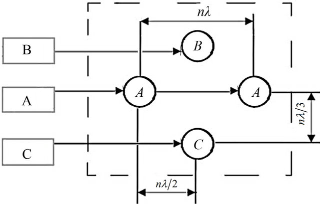
Figure 1. Modular ultrasonic generator circuit: A, B, C— modules and accordingly piezoelectric converters.
generators are phase shifted on 120˚. The area of the maximal acoustic pressure consistently moves in liquid from the converter A to B and from B to C in each group.
As a result of frequency modulation direct streams in liquid pass from the zone of greater acoustic pressure to the zone of lower pressure.
Whirlwind macro streams alongside with microstreams in a viscous boundary layer near to obstacles intensify processes of diffusion and dissolution of pollution.
2.2. The Automated Cleaning Line
The automated cleaning line (Figure 2) consist of six US clearing baths equipped with mechanisms of fast immersing of cartridges with details (10 - 15 mm/c) and slow extraction (1.0 mm/c), the module of the drying, two auto operators, electric equipment and a control system on the basis of the programmed controller. The control system provides performance of the following functions: input, indication and change of technological parameters; an output at a zero point of both auto operators and moving of mechanisms swing, dry and cleaning; inclusion of heating in baths and the module of drying, maintenance temperature at the set level from 20 up to 80˚C, and carry cartridges from one bath in another. The productivity of automated cleaning line is up to 4500 modules/hour.
The software of a control system allows forming the managing program for technological processes with the different algorithms of work distinguished by sequence of passage of baths with washing solutions, time of clearing, and temperature.
The automated cleaning line allows carrying out cleaning in baths with different structures and with various times. Combinations of modules and easily readjusted microprocessor control system allow making simultaneous cleaning of a surface of details from chemically proof and unstable materials.
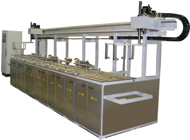
Figure 2. Automated cleaning line.
2.3. Cavitation Pressure Measurements
Cavitations intensity in liquid solutions is measured by comparing by weight of test samples before and after cavitation. But mistake of this method makes up to 25% due to heterogeneity of cavitation areas and other random factors. The estimation of erosive activity is facilitated, if take a thin aluminum foil with thickness of 0.05 mm and estimate the area of its destruction on various distances up to a radiator. The method disadvantages are a long time of measurement.
Cavitation field in liquids has complex spectral structure as bubbles form and close in random and the acoustic radiation caused by them is shown as broadband noise with a spectrum in a strip up to hundreds kHz. On a general background of a spectrum cavitation noise discrete subharmonics components, which characterize occurrence of cavitation are observed.
The spectral analysis of the signals form of decomposition in number Fourier of a harmonic of high frequencies nf0 (n = 1, 2, 3), subharmonics ,
, , and the “white” noise, which is generated by cavitation bubbles of the various resonant sizes.
The spectral research of cavitation noise in a band of 20 kHz - 50 MHz with the help of the spectrum analyzer and the sensor, which were placed in cavitation area of a liquid, showed that the maximal growth in a spectrum gives continuous noise and also subharmonics [5]. The greatest spectral density of cavitation noise is between 20-th up to 40-th harmonic of the basic US frequency.
Cavitations pressure in the solutions is estimated by the intensity of square-law size of a level of noise in a range of its greatest spectral density with the help cavitations pressure indicator. The cavitations pressure indicator consists of the probe 1, piezoelectric converter 2, strip filter 3, square-law detector 4, amplifier 5 and the recording device. This indicator (Figure 3) measures cavitations pressure from 5 up to 5·104 Pa in a range of frequencies 18 - 60 kHz with accuracy ±10%.
The strip filter of the third order of Chebushev circuit allocates a part of a spectrum of a signal, which is characteristic for cavitation pulses. Indicator readings register cavitation pressure after 1 - 2 sec. when cavitation process is stable.
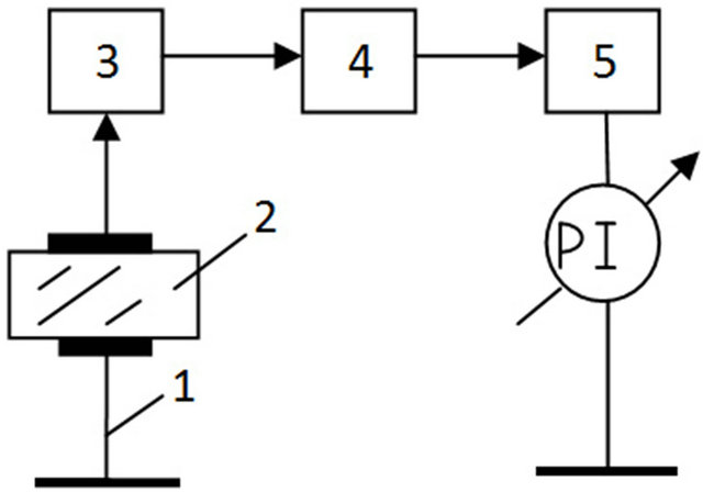
Figure 3. Cavitations pressure indicator.
3. Modelling of US Pressure Distribution
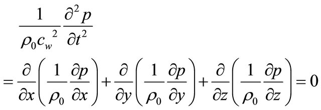
An actual problem is optimization of parameters of US field in baths of group processing, an establishment of laws of physical and chemical processes of clearing profile and microrelief surfaces of optical and electronic modules in liquid washing environments at frequency and phase modulation US of a signal. Distribution US pressure in liquid is described by the wave equation:
 , (1)
, (1)
where ρ0—solution density; p—pressure; cw—US speed wave; t—time; x, y, z—coordinates.
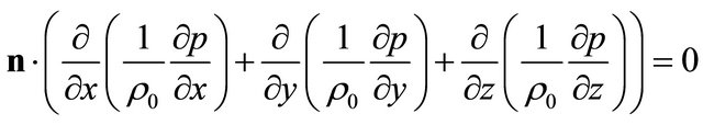
The Equation (1) dared taking into account boundary conditions (2 - 5) and by means of СOMSOL for three variants of arrangement US converters A, B and C at the bottom of a bath [6].
 , (2)
, (2)
 ; (3)
; (3)
 ; (4)
; (4)
 . (5)
. (5)
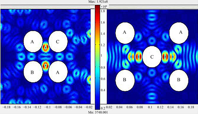
Modeling showed, that the maximum amplitude of pressure US waves is observed at a surface of radiators and on the distances equal λ. More uniform US field on volume of a bath as a result of superposition of waves is created for an arrangement of radiators in knots of triangular structure with length of the party, multiple  (Figure 4).
US of pressure in bath volume influences distribution presence at the liquid environment of firm bodies which certain degree reflect US waves. Stronger influence on distribution of pressure the cartridge with the details, located on distance, multiple λ from a bath bottom (Figure 5). At the expense of reflexion from surfaces of details US pressure in adjoining layers of a liquid increases.
The important factor in US cleaning is non-uniformity cavitation pressure in a bath. With cartridge in the bath non-uniformity cavitation pressure increases and nonuniformity growth (Figure 6) because reflexion of waves from its surface.
The dependence of cavitation pressure from temperature of the solutions and concentration of SAS were investigated. If temperature raise cavitation pressure decreases, as elasticity pair in cavities raises and their kinetic energy decreases, this results in reduction of shock
 (a) (b)
Figure 4. Distribution US pressure on the bath area with linear radiators arrangement (a) and triangular structure (b).
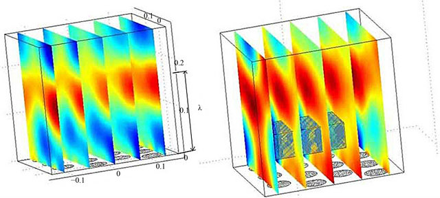
Figure 5. Distribution US of pressure in a bath: without cartridge (1) and with the cartridge (2).
waves intensity. Simultaneously, there is a formation of new, filled the steam bubbles, that results in expansion of cavitation area and to reduction of non-uniformity of its distribution.
The speed of decrease in cavitation pressure with growth of washing environment temperature depends on its physical and chemical properties. The speed of change in clean water (curves 1, 2) is less than for water solutions SAS (curves 3) (Figure 7).
SAS reduces force of a superficial tension that results in decrease in a threshold cavitation, in growth of number bubbles and in increase of uniformity of cavitation fields. However, the reduction of force of a superficial tension reduces speed of cavitation bubbles closure and
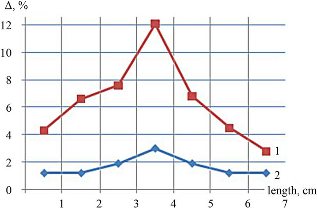
Figure 6. Non-uniformity cavitation pressure with the cartridge (1) and without it (2).
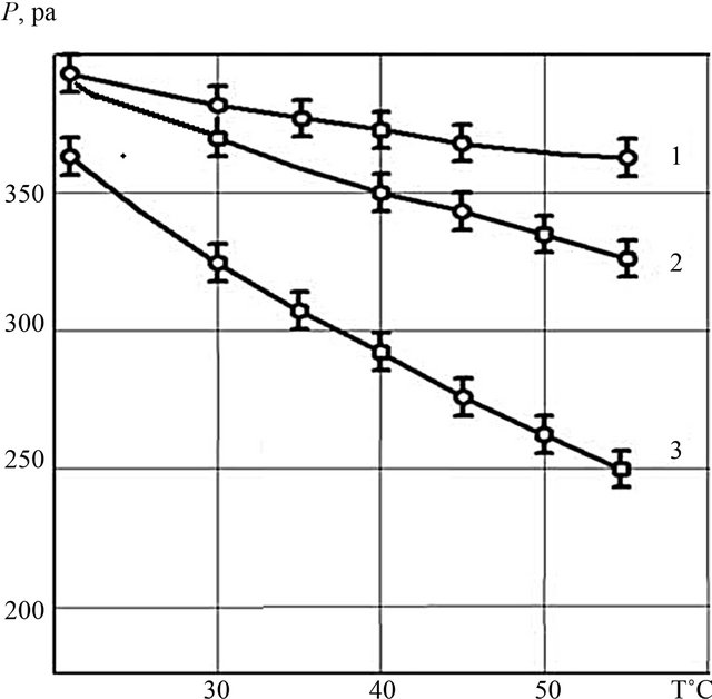
Figure 7. Cavitations pressure vs. Temperature and SAS concentration: 0% - 1%, 1% - 2%, 1.5% - 3%.
reduces the micro shock of cavitation action. With the rise of temperature the influence of SAS grows.
With increase in concentration of SAS their influence amplifies. However to increase it over 10% is not a good in view of difficulty of the subsequent removal. It is possible to establish such temperature modes at which efficiency of influence US fluctuations and SAS will be optimum by measuring cavitation pressure.
4. Conclusion
Optimization US field parameters in baths have allowed to raise productivity, improve working conditions, lower losses due technological flexibility, heating and convection air for drying. For US cleaning the optimum temperature water solutions SAS is 40˚C - 50˚C, and 1% - 2% concentration SAS.
REFERENCES
- W. D. Brown and R. K. Ulrich, “Advanced Electronic Packaging,” 2nd Edition, IEEE, New York, 2006.
- T. G. Leighton, “The Acoustic Bubble,” Academic Press, London, 1994.
- V. L. Lanin and V. S. Tomal, “Ultrasonic Cleaning Technology of Electronics Products,” Electronics and Electrical Engineering, Vol. 3, No. 383, 2008, pp. 49-52.
- V. L. Lanin, “Increasing the Efficiency of Ultrasonic Clearing by Means of Direct Action of an Electric Field in Liquid Media,” Surface Engineering and Applied Electrochemistry, Vol. 4, No. 44, 2008, pp. 301-304. doi:10.3103/S1068375508040108
- V. L. Lanin, N. V. Dezhkunov and A. V. Kotukhov, “Application of Ultrasonic Effects in Liquid Media for Fabrication of Nanomaterials,” Surface Engineering and Applied Electrochemistry, Vol. 3, No. 46, 2010, pp. 301- 304.
- V. L. Lanin, V. S. Tomal and V. I. Zakharevich, “Acoustic Fields and Microstreams Modelling in Ultrasonic Clearing Baths,” Electronics and Electrical Engineering, Vol. 2, No. 90, 2009, pp. 107-110.