Wireless Engineering and Technology
Vol.3 No.1(2012), Article ID:16939,6 pages DOI:10.4236/wet.2012.31005
Intellectual CAD for Three-Tier Wide Band WDR Filters
![]()
National Technical University “Kharkiv Polytechnic Institute”, Kharkov, Ukraine.
Email: AGYu@kpi.kharkov.ua
Received August 28th, 2011; revised September 14th, 2011; accepted October 10th, 2011
Keywords: Intellectual CAD; Waveguide-Dielectric Filters; Expert System; Optimization Methods; Wide Band Pass
ABSTRACT
The paper presents an original physical points of an intellectual CAD system designing for three-tier wide band waveguide-dielectric filters with LM modes. On the basis of formalized physical knowledge about the behavior of coupled resonators, the CAD system analyses electromagnetic signal passing through a filter structure and makes decisions gradually approaching the optimal filter design through a series of changes in its geometry. From a mathematical point of view, this approach is an alternative to well-known optimization methods and is also very promising for solving the problem of finding a global extremum of an objective function. We also include the filter optimization results obtained with the CAD system for the frequency range 23 - 81 GHz, band widths up to 30% and insertion losses less than 0.5 dB.
1. Introduction
Microwaves are used in telecommunication (and radar) systems of centimeter and millimeter wave bands, which effectively support information channels in computer networks and networks of mobile cellular communication. Characteristics of microwave repeaters depend significantly on electric parameters of band pass filters they contain. Among known microwave filters, the designs based on leukosapphire and quartz waveguide-dielectric resonators (WDR) are distinguished due to their general quality parameters, such as high unloaded Q’s, sparse spectrum of parasitic modes and usable level of transmitted power [1,2]. Cross-shapes of the cut-off waveguide cross-sections enable to fix there Eand H-plane resonance size dielectric inserts by means of projections [3]. Quartz and leucosapphire monocrystals are used as dielectric materials in designing band-pass filters for millimeter wave band, thus ensuring that the dimensions of inserts are suitable for manufacturing process and unloaded Q of the working type electromagnetic modes is induced in the inserts.
For many applications it is necessary to deal with wide band frequencies, for which WDR-based filters seem to be very promising too. However no complex studies have been performed in this area yet, which makes the development of theoretical approaches to solving this problem rather actual now.
2. Filter Synthesis and the Basic Idea of the Expert System Desiging
The traditional methods of filter synthesis are based on various prototypes from the circuit theory with concentrated or distributed parameters. Their basic disadvantage is that they don't account for higher wave types induced on filter discontinuities. So it seems necessary to take a combined approach where parameters of prototype models serve as input to a numerical optimization procedure using gradient methods based on rigorous electrodynamics models [4,5]. Lately one can notice the intensive attempts of effective search numeral and numeral-analytical algorithms of solving this problem [6,7], including technologies of artificial intelligence [8-10]. However much considerable progress nevertheless cannot be achieved, both in areas of universal algorithms development construction and in the applied tasks, concerning this class of devices. The attempts of filters design simplification to the level proper to CAD possibilities are even undertaken on occasion [11]. The common drawbacks of direct and combined numerical optimization methods are insolvability of the problem of finding the global extremum of the objective function and exponential growth of calculation time with the increase in the number of resonators or the accuracy of calculations. It should be understood, that the principal cause of the low efficiency of the optimization methods is due to the fact that the overwhelming majority of parameter values is meaningless from the point of view of process modeling physics. In this paper, we propose an alternative method of intellectual synthesis of a wide band filter design, which is based on formalized knowledge about the physics of coupled resonators. The basic idea of the expert system (ES) described here consists in physical analysis of signal passing through the filter [12], which is performed on the basis of known solution of electrodynamics problem of scattering of electromagnetic wave  in threetier structure shown in Figure 1 [13].
It should be noted that coupling of Hand E-waves (or LM and LE waves in basal planes) is determined by the size of projections of the crossed waveguide, and the projection size is a decisive factor determining the spectrum dynamics of eigenmodes. In our case, we use projections of the crossed waveguide to fix the inserts. That’s why according to our opinion the size of projections  is small
  (where A is width of cutoff waveguide) and therefore there is no coupling between Eand H-waves. The value
  clearance between an insert and the waveguide walls is chosen compromising between increase of unloaded Q of the working mode and densification of parasitic mode spectrum;
  where B is the waveguide height. This enables us to describe wave processes in this structure with the help of effective dielectric permittivity of equivalent inserts completely filling the rectangular cut-off waveguide. The problem of scattering was solved by the mode matching method. The algorithm of approximate synthesis allowed us to reduce the time of development and obtain an acceptable filter response even after the first iteration. To eliminate the influence of both the calculation error and manufacturing process, we provide adjusting screws symmetrically above each dielectric insert [2, 3]. The calculations were carried out for 30 wave types in a regular waveguide and one wave type in a cut-off waveguide [13]. The comparison of the computed and measured results shows that they are corresponded well enough even with so simple approximation: the errors are less than 1.5% in both cases, i.e. for frequency and insertions losses.
On the basis of expert physical analysis of frequency response topology of filtering structure, conclusions can be made as to the current status of the system and the ways to approach the optimum parameters. The knowledge base (KB) is implemented with production rules because: 1) this is the most suitable way of simulating intellectual work of an expert in this domain; 2) the formalized expert knowledge is both of procedural and declarative character; 3) the knowledge base has rather complex structure; 4) the order of application of the rules for the problem solving is important; 5) this form allows simple modification. The logical structure of the software is presented in Figure 2. It consists of three program modules. FR1 (one-tier filter) and FR3 (three-tier filter) are independent program modules that operate with the data and carry out computing operations under control of the ES, which contains a KB consisting of production rules and a fact base (FB). The rule interpreter compares conditional parts of the rules with the current facts and executes the best matching rule. The rule application history documents the way the system reaches its final

Figure 1. The three-tier microwave filter design with H-plane leukosapphire plates.

Figure 2. Logical structure of the software: The program modules FR1 and FR3 calculate frequency responses of singleand three-tier filters, correspondingly.
decision.
3. Software Tools and Intellectual CAD Interface
The following tools were chosen for development of the intellectual CAD system: 1) C/C++ language, ANSI standard; 2) Borland C++ Builder 6.0 as the integrated design environment; 3) Borland C/C++ compiler—because they facilitates expert knowledge formalization on the high level suitable for realization of all program modules and support creation of convenient and userfriendly interface (Figures 3-5). The program window shown in the figures is divided into following panes.
· Filter settings pane contains a text box for working frequency input and displays the current values of the filter insertion loses topology during the system operation (central frequency and bandwidth) as well as the data on the current state of expert system operation.
· Stage of designing pane displays information on the fulfilled intermediate process stages.
· Frequency response pane plots frequency and amplitude of a signal passing through the filter structure.
· The status line below displays information about the logical rule currently applied or the conclusion achieved.
4. Key Stages of Filter Design
The filter design stages are illustrated below. Figure 3 demonstrates the concluding stage of FR1 calculating the length of the central resonator with quasi  mode under working frequency of 70 GHz. Frequency response image shows resonance splash proper to the current geometrical parameters of structure.The search algorithm is based on the following rules: “if resonator central frequency is less than the working one, the resonator length should be reduced” (and vice versa), those results in relocation of resonance splash on a frequency axis, when splash corresponds to working frequency, KB system passes to optimization of three-tier structure.
Figure 4 shows the three-tier filter optimization procedure performed by FR3 module. Frequency response image shows three resonance splashes, which correspond frequencies of coupling resonators. Inequality insertion losses on the right and on the left from central splash differentiate, they are lined up by the selection of frequency difference of central and outermost resonators. The following rule is being applied: “if the left insertion losses maximum is more than the right one, the lengths of the outermost resonators should be increased” (and, vice versa).
Sequential application of the rules leads to the band
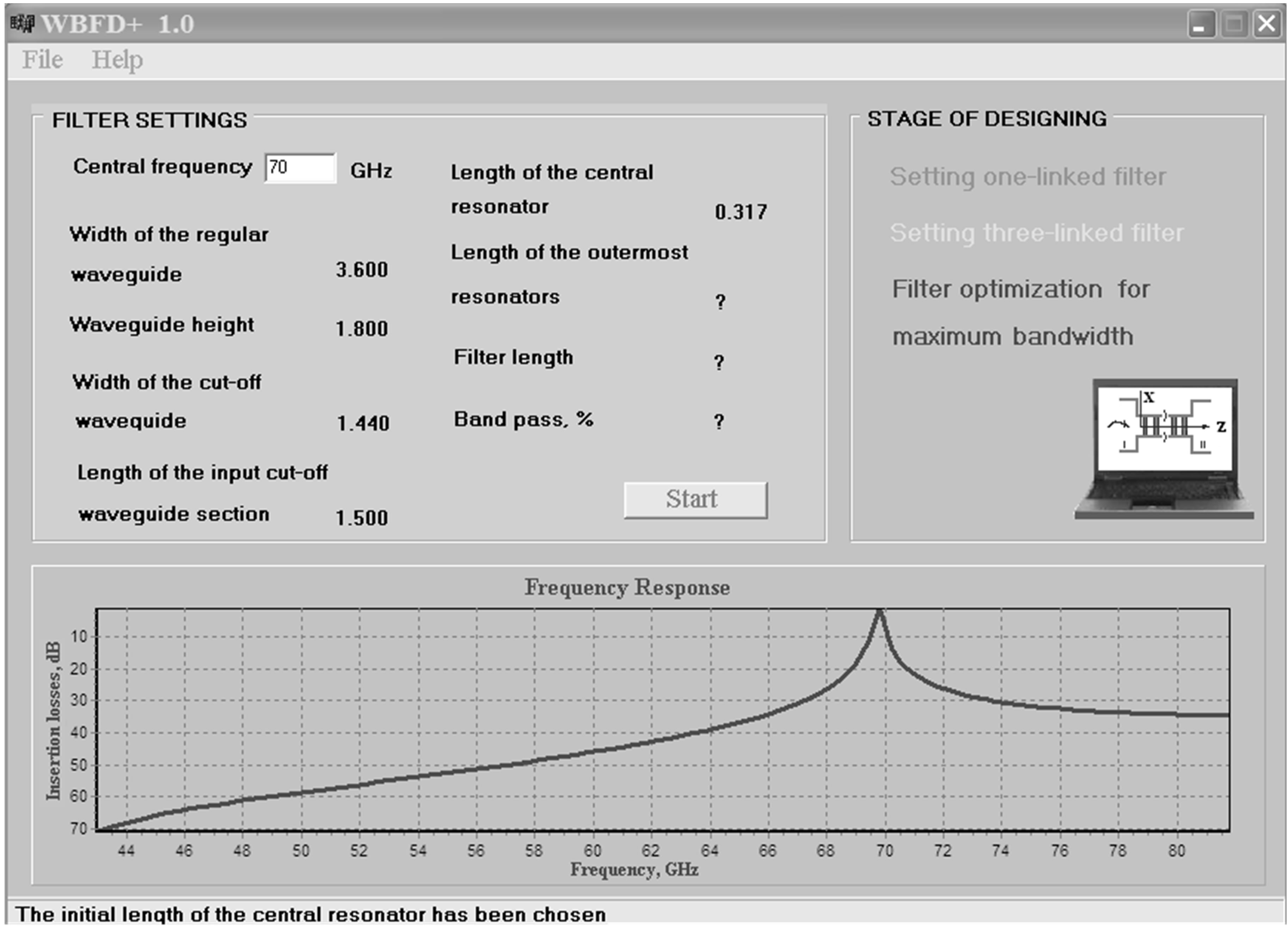
Figure 3. The intellectual CAD results at regime of FR1 module for one-tier filter.
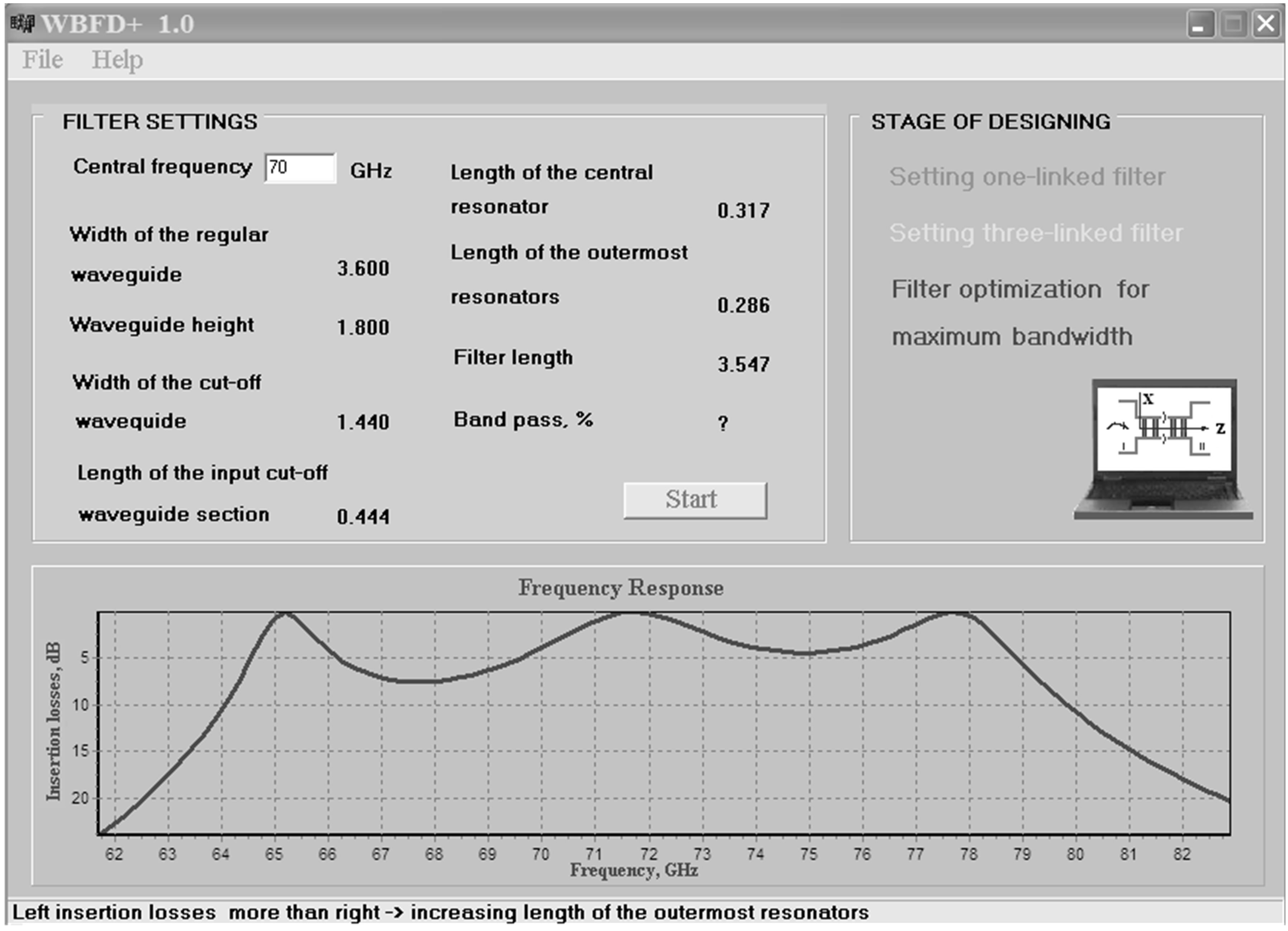
Figure 4. The intellectual CAD results at regime of FR3 module for three-tier filter.
pass losses alignment shown in Figure 5.
5. Intellectual CAD Wide Band Filter Designing Results
The table below (Table 1) contains the results of filter optimization with the intellectual CAD system done for the frequency range 23 - 81 GHz. In all cases the insertion losses are less than 0.5dB, (leukosapphire and quartz insets).
Width and height of regular waveguide corresponds to the standards accepted in the former USSR and now are in force in Ukraine, dielectric permeability is chosen between the requirements of filter miniaturization and technological of its manufacturing at mass production. It should be mentioned that an integral method of non-destructive testing of optically transparent dielectric elements in band pass filters has been developed. Putting it into practice allows to guarantee reproduction of filters electric parameters during their mass production [14].
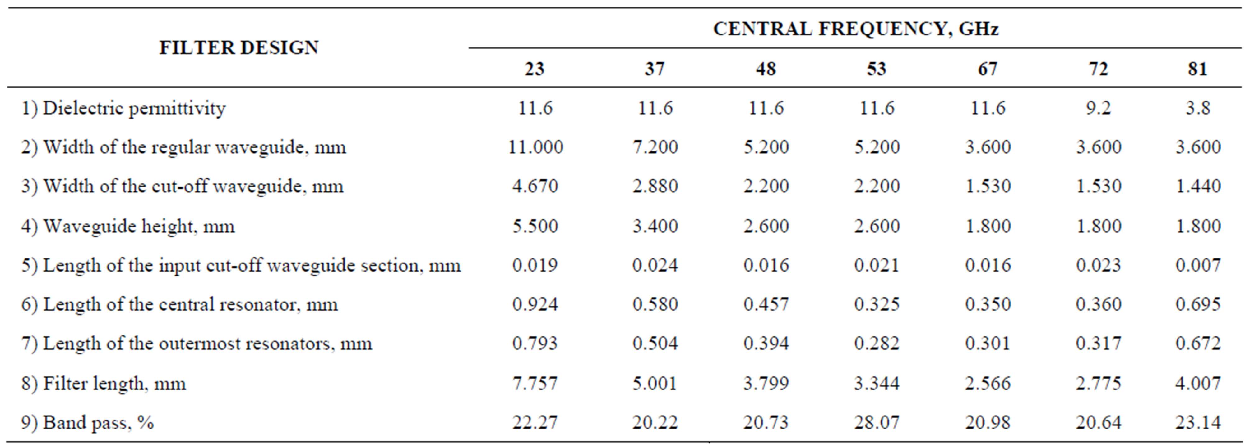
Table 1. The results of filter optimization.
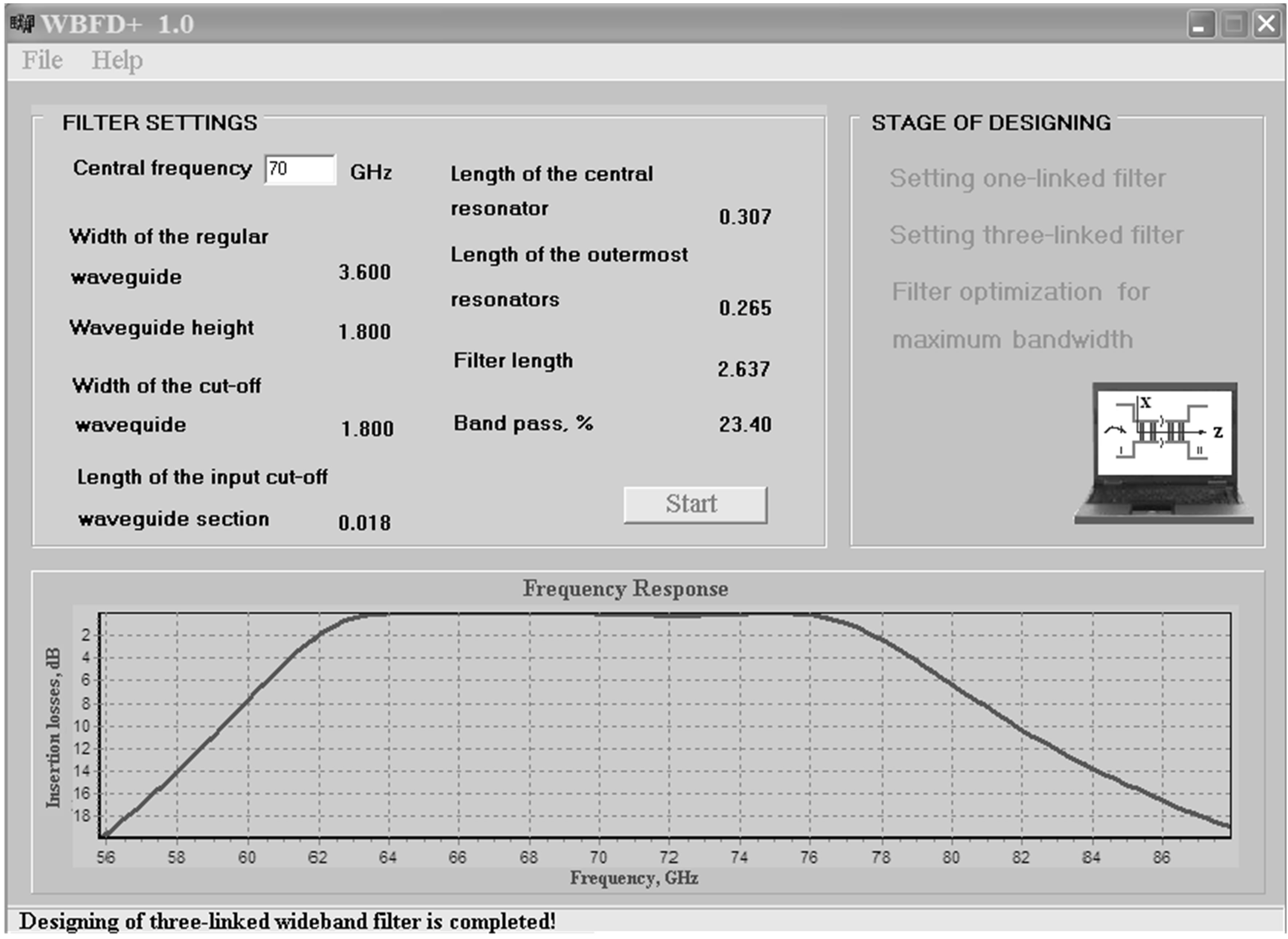
Figure 5. The intellectual CAD system results of three-tier wideband filter design and optimization of its response characteristics.
According to the results of filter optimization we can conclude that the maximum band width that can be reached depends on the position of central filter frequency relative to the frequency range borders of rectangular waveguides and insets permittivity.
6. Conclusions
Thus, the developed intellectual CAD system effectively solves a problem of designing optimal three-tier wide band microwave filters and may be considered as a prototype for designing filters with more tiers. High speed of calculations is the distinctive feature of the intellectual system from the known ones, practically every successive step in calculations changes frequency response in the direction of all greater approximations to optimum, at the chosen values of dielectric permeability and width of cut-off waveguide. Thus, the system creates a base from the calculated variants of filters, giving possibility of manifest the best, as per the chosen criterion; in our case it is the maximal band pass at an erratical response no more than 0.2 dB.
The efficiency of intellectual CAD depends only on the accuracy of the analysis problem solution and the exactness with which the application conditions of the rules applied match the data. Therefore it is high enough: the errors are less than 2% in both cases, i.e. for frequency and insertions losses.
It is hypothesized that further increase of filters band pass is possible to reach by using filters design on the base of different classes resonators [2], what expansion of knowledge base of consulting model may be needed for.
REFERENCES
- A. G. Yushchenko, “Waveguide-Dielectric Filters Based on Leukosapphire and Quartz Monocrystals,” SPI’s International Symposium on Voice, Video and Data Communications, Vol. 3232, Dallas, 1997, pp. 73-79. doi:10.1117/12.301020
- A. G. Yushchenko, “High Unloaded-Qs WDR Filters Designing,” International Journal of Infrared and Millimeters Waves, Vol. 22, No. 12, 2001, pp. 1831-1836. doi:10.1023/A:1015031802727
- A. G. Yushchenko, et al., “Microwave Filter,” Buluten Izobreteniy, in Russian, Patent of Russia Federation №. 2040080, 1995.
- H. Liu, “A Rigorous CAD of Millimeter wave Bandpass Filter with All-Metal Insert in Waveguide,” International Journal of Infrared and Millimeters Waves, Vol.13, No. 9, 1992, pp. 1387-1393. doi:10.1007/BF01009995
- V. Postoyalko and D. S. Budimir, “Design of Waveguide E-Plane Filters with All-Metal Inserts by Equal Ripple Optimization,” IEEE Transactions on Microwave Theory and Techniques, Vol. 42, No. 2, 1994, pp. 217-222. doi:10.1109/22.275250
- J. W. Bandler, Q. S. Cheng and S. A. Dakroury, “Space Mapping: The State of the Art,” IEEE Transactions on Microwave Theory and Techniques, Vol. 52, No. 1, 2004, pp. 337-361. doi:10.1109/TMTT.2003.820904
- J. V. M. Ros, P. S. Pacheco, H. E. Gonzalez, V. E. B. Esbert, C. B. Martin, M. T. Calduch, S. C. Borras and B. G. Martinez, “Fast Automated Design of Waveguide Filters Using Aggressive Space Mapping With a New Segmentation Strategy and a Hybrid Optimization Algorithm,” IEEE Transactions on Microwave Theory and Techniques, Vol. 53, No. 4, 2005, pp. 1137-1141. doi:10.1109/TMTT.2005.845685
- R. Thabet and M. L. Riabi, “Design of Metallic Cylindrical Waveguide Bandpass Filters Using Genetic Algorithm Optimization,” Progress in Electromagnetics Research Symposium Abstracts, Moscow, 18-21 August 2009, pp. 785-786.
- M. Yahia, J. W. Tao, H. Benzina and M. N. Abdelkrim, “Ridged Waveguide Filter Optimization Using the Neural Networks and a Modified Simplex Method,” International Journal of Innovation, Management and Technology, Vol. 1, No. 3, 2010, pp. 259-263.
- K. Humayun, “Advanced Neural Network Modeling Techniques for Efficient CAD of Microwave Filters,” Carleton University, Ottawa, 2009.
- S. Amari, J. Bornemann and U. Rosenberg, “PseudoElliptic Waveguide Filters without Cross Coupling,” 31st European Microwave Conference, London, 24-26 September 2001, pp. 1-4.
- A. G. Yushchenko and D. M. Zaytsev, “Intellectual Modeling of Three-Tiered Microwave Filters,” in Russian, Vestnik NTU “KhPI” No. 4, 2001, pp. 285-288.
- M. E. Ilchenko, A. G. Yushchenko, S. F. Shibalkin and V. V. Popov, “Waveguide-Dielectric Filters Based on cross Shaped Waveguides,” International Conference on Millimeter and Submillimeter Waves and Applications, Vol. 2250, San Diego, 10-14 January 1994, pp. 571-572 .
- A. G. Yushchenko and V. V. Chizhov, “Integral Method of Nondestructive Testing of Optically Transparent Dielectric Elements of Band Pass Filters,” International Journal of Infrared and Millimeters Waves, Vol. 14, No. 6, 1993, pp. 1353-1366. doi:10.1007/BF02146262