Wireless Engineering and Technology
Vol.1 No.2(2010), Article ID:3029,7 pages DOI:10.4236/wet.2010.12012
On the Design of Circular Fractal Antenna with U-Shape Slot in CPW-Feed
![]()
Microwave and Millimeterwave Antenna Lab., Department of Electronics Engineering, Defence Institute of Advanced Technology (DU), Girinagar, India.
Email: omnamhshivay2010@gmail.com
Received July13th, 2010; revised August 4th, 2010; accepted August 24th, 2010.
Keywords: Monopole Antenna, Wideband Antenna, Resonant Frequency, Fractal Antennas, Multib, Antenna
ABSTRACT
A new ultawideband circular fractal antenna with notched-band characteristics is presented. A notched-band characteristic is achieved by employing a U-shape slot in 50 Ω feed lines. The ultra-wideband impedance matching and compact size have been obtained by using CPW-feed technique and the fractal concept. The measured result of proposed fractal antenna exhibits the ultra wideband characteristics from 3.0 to 18.0 GHz at VSWR 2:1 except notched-band frequency. The proposed antenna has been analyzed theoretically and experimentally with respect to design parameters. The measured radiation pattern of fractal antenna is nearly omnidirectional in azimuth plane throughout the operating frequency. This antenna is useful for UBW communication system.
1. Introduction
Ultra-wideband (UWB: 3.1-10.6 GHz) communication system has become more and more popular because of its advantages such as small size, high transmission rate, and low power consumption comparing with current wireless communication system [1]. Because of these advantages of an UWB system, significant research in the UWB antennas has been aroused in academic and industrial fields recently. However, over this allocated band, there are some existing narrow band services, such as IEEE 802.16 WiMAX system operating at GHz, and C-band satellite communication systems, which may cause electromagnetic interference to the UWB system. Thus, the UWB antenna with notched-band performance is required. The several UWB antennas with the notched frequency function have been reported [2-4], such as, attaching U-shaped slot, inverted U-slot, arc-shaped slot, C shaped slot, or small strip bar to the antenna. The UWB fractal antennas with notch have been reported for UWB applications [5-8]. In [5], Crown - Sierpinski microstrip antenna is proposed to reduce the size of a Crown square fractal. The frequency notched ultra-wideband microstrip slot antenna with a fractal tuning stub is proposed to achieve frequency notched function [6-7]. Raj Kumar et al. [8-9] have proposed a new UWB fractal antenna by adopting the fractal concept on the CPW-fed circular UWB antenna. This work proposed the UWB fractal antenna band-notched characteristics with detail study.
In this paper, a new circular fractal antenna with band-notched is proposed for the UWB system applications. The notched band is easy to tune by changing the length and width of the slot. The antenna has advantages of compact size, low manufacturing cost, easy fabrication, low profile, and very small ground plane suitable for integration with compact UWB systems. The performance of the proposed antenna is characterized in term of impedance bandwidth, band-notched and radiation pattern.
2. Antenna Geometry and U-Shape Slot
The iteration wise fractal antenna was constructed from simple conventional monopole antenna as shown in Figure 1. The solid circular monopole antenna has been designed on FR4 substrate εr = 4.3, h = 1.53 mm, with radius 9.1 mm. This is called the initiator or zeroth iteration shown in Figure 1(a). The first iteration of fractal antenna has been constructed by inscribing the square patch of dimension 12.8 × 12.8 mm inside the circle and subtracted it from circle. This is called 1st iterative inscribed square circular fractal antenna as shown in Figure 1(b). The 2nd iteration has been achieved by making the circle of diameter 12.8 mm and an inscribed square of dimension 9.05 × 9.05 mm has been subtracted from this inner one circle as shown in Figure 1(c). The 3rd iteration is constructed by making the metallic circle of 9.05 mm diameter inside the square touching the metallic part of its and subtracting an inscribed square of dimension 6.4 × 6.4 mm as shown in Figure 1(d). In the fourth iteration, a circle of diameter 6.4 mm is made and an inscribed square of dimension 4.525 mm × 4.525 mm is subtracted as shown in Figure 1(e). This process can be repeated up to infinite iteration. Practically infinite iterative structure is not possible because of fabrication constraints. The fourth iterative fractal antenna has been finalized to design on the same substrate dielectric constant and thickness as conventional microstrip monopole antenna as shown in Figure 1. This antenna has been fed with the coplanar feed. The CPW-Fed and radiating elements both are printed on the top side of a low-cost FR-4 substrate with dielectric constant εr = 4.3, h = 1.53 mm and loss tangent tan δ = 0.02.
Figure 1 shows the geometry of the proposed fractal antenna. It is composed of inscribed square circular fractal radiating elements, fed by a U-shape slotted CPW-feed with a very small ground plane. There is no ground plane at the bottom of the substrate. It is known that CPW-feed is advantageous for less dispersion at higher frequency, broader matching, easy fabrication and integration with MIC/MMIC. The CPW-fed antenna not

Figure 1. Inscribed square circular fractal antenna with va-rious iteration.
only performs better in respect of bandwidth and but radiation pattern is also good [8]. In coplanar feed, the feed of antenna and radiating elements are printed on the same side of the substrate. A slot is inserted of U-shape in 50 Ω feed line of coplanar waveguide to create the notched frequency band. The resonant frequency of the notched band is defined by the effective length of the slot and band-notched frequencies by width of the slot. It can be seen by changing the L and W, notched-band frequencies can be controlled. The notched frequency bandwidth is controlled by varying the width of slot, while notched-band resonant frequency can be controlled by changing the length of slot. To validate the design the band-notched at frequency from 3.635 to 3.935 GHz, the slot length of 10 mm and width 0.4 mm have been taken which can be redesign according to the requirement. A parameter studies with respect to slot width and length have been done.
3. Fractal Geometry for Compact Size and UWB
A simple circular disc monopole antenna with slotted CPW-fed is shown in Figure 1(a). It is understood that current distribution of the proposed antenna is mainly along the circumference of the circular disc. The current density is low in the middle area of the solid circular disc monopole antenna as shown in Figure 2. Therefore, the current will not be affected if the middle area of the solid circular disc monopole antenna is removed. In this way, the effective path of the surface current will become longer. In this antenna, the effective length of current path is increased by inscribing square in solid circular disc. This resulted, the first resonance frequency will be decreased and the size of the antenna will be reduced.
To achieve the UWB characteristic, the fractal structure can be added to increase the resonance frequency in
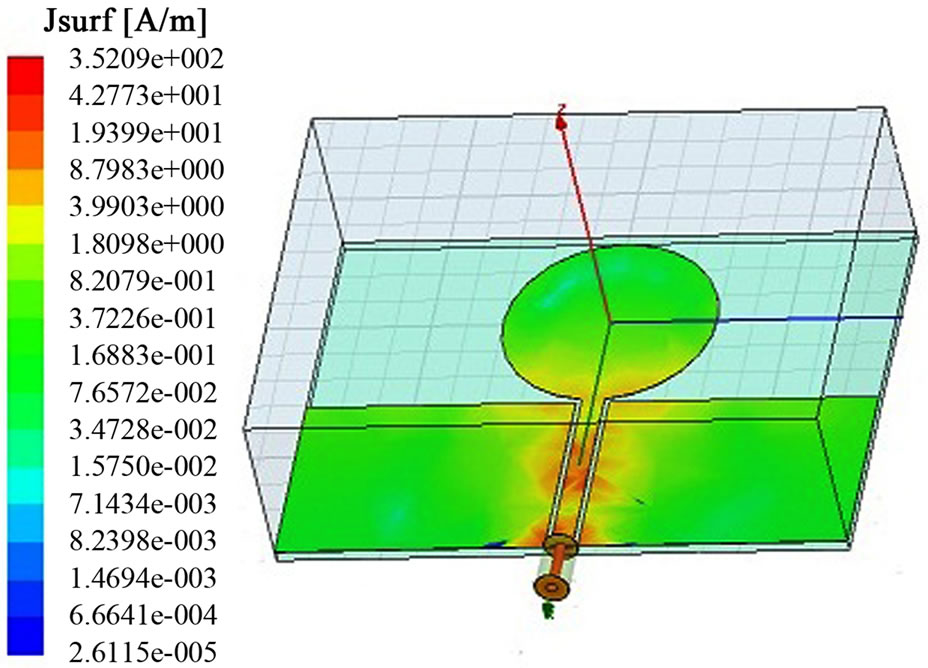
Figure 2. Current distribution on the circular disc monopole antenna.
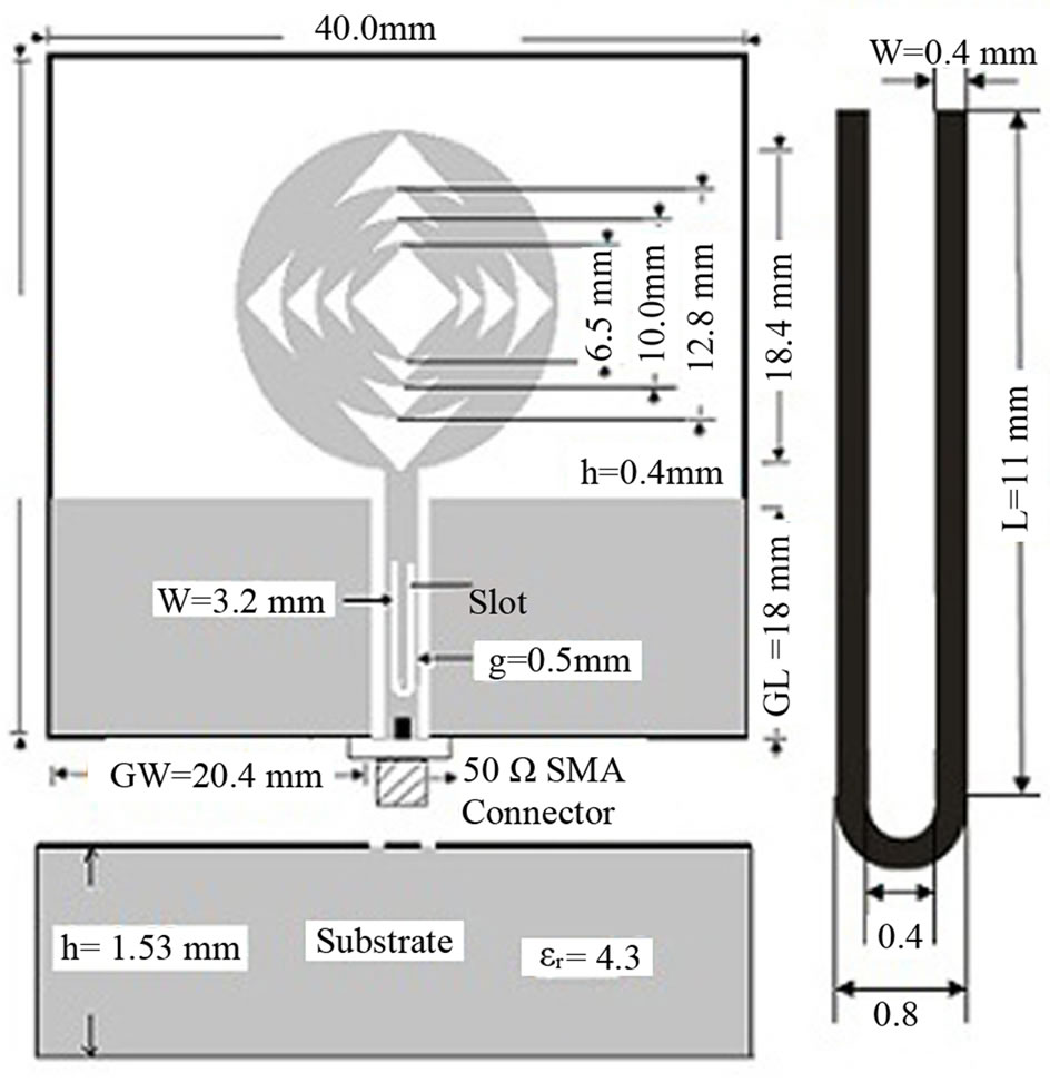
Figure 3. Proposed circular fractal antenna with slot dimension.
high frequencies by adding resonance elements in solid circular disc antenna. In this paper, resonance elements have been added by inscribing square in various concentric circles as shown in Figure 1. The proposed fractal antenna structure has been shown in Figure 3 with slotted CPW-fed. The 50 Ω impedance is achieved by adjusting the width W = 3.2 mm of the inner conductor and the gap between the ground plane and feed width is g = 0.5 mm. To achieve the UWB characteristic, the gap between patch and ground has been optimized to h = 0.4 mm. The length of ground plane GL = 18 mm and width of the ground plane 20.4 mm have been optimized.
4. Simulated Results
It is noticed in simulation that the operating bandwidth of the proposed antenna is heavily dependent on the gap between patch and ground, iteration number and notched-band depends on length of slot and width of slot. The UWB characteristic depends upon the parameters gap between patch and ground, and iteration number. But notched-band characteristic depends upon the length and witch of the slot. First the parameters for maximum bandwidth have been optimized with fixed slot dimension. The antenna has been simulated for each iteration. The simulated result of each iteration is shown in Figure 4.
It is clear from the Figure 4, as the iteration increase the first resonant frequency shifted towards lower frequency side. This shift indicates the size reduction of the antenna. It is also found that as the number of iteration increases, the lower-edge of the impedance bandwidth is
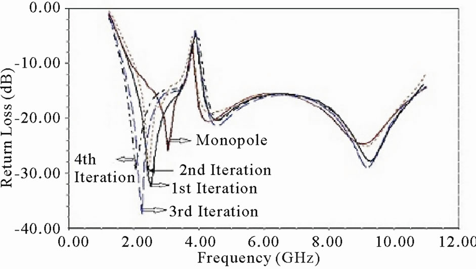
Figure 4. Simulated result of fourth iterative fractal anten-na with respect to various iteration.
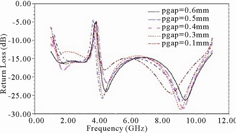
Figure 5. Simulated result of fourth iterative fractal antenna for various value of gap between patch and ground.
moved to the low frequency and the level of the impedance matching over the operating frequency band is improved. The fourth iterative fractal antenna gives the impedance matching in UWB characteristic.
From Figure 2, it can be seen that current is mainly distributed on the upper edge of ground plane and along the edge of antenna disc, which explains why the performance of the antenna is critically dependent on the gap h between ground and patch. The parameter h is very critical parameter for proper coupling from feed line to patch which effect the UWB characteristic. The proposed fractal monopole antenna has been simulated for various values of gap. The simulated results have been shown in Figure 5. It has been observed from graph that gap (h) between ground and patch effects the lower end frequency and bandwidth. The fourth iterative proposed fractal antenna has been fabricated with gap h = 0.4 mm, 50 Ω feed with W = 3.2 mm and g = 0.5 mm.
5. Notched-Band Characteristic
The effect of these design parameters on UWB characteristics and band-notched characteristics are because of current distribution over radiating elements, ground plane, feed line and U-type slot. Figure 6 shows the current distributions at 3.2 GHz and 3.8 GHz frequency for
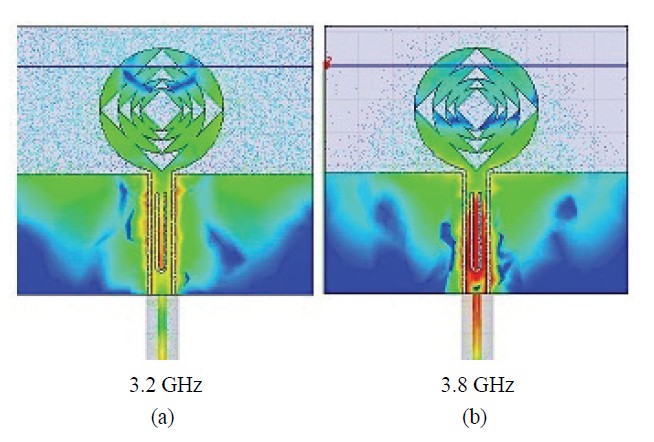
Figure 6. Current distribution over slot at notched and without notched frequency.
the optimal design parameters. In Figure 6(a), where the antenna operates at pass band frequencies 3.2 GHz, there is more current distributions near the feeding point (i.e., slot does not resonate and has little effect). At notch frequency, 3.8 GHz, as shown in Figure 6(b), current is concentrated around the edge of the slot while there is almost no current at the feeding point.
It reveals that the currents mainly concentrate around the slots at the notched frequency, which indicates the width/length/position of slots can actually play significant roles in the performance of the band-notched characteristics of proposed antenna. This leads to the desired high attenuation and impedance mismatching around the notch frequency. This demonstrates the notch-band function of the antenna and therefore elimination of interfering signals within the UWB spectrum.
As it can be seen the proposed antenna provides UWB characteristics with band-notched frequencies. The band-notched frequency happens at 3.635 to 3.935 GHz for filtering the interfering signal. It can be seen by changing the length (L) and Width (W), resonant frequency and band-notched can be tuned. The resonant frequency of the notched-band depends on the length of the slot and notched bandwidth depends upon width of the slot. It is clear as length of slot increases, the band-notched resonant frequency shifts to the lower side. As the length of slot increases from 3 mm to 13 mm, the resonant frequency of band-notched shifts to lower frequency side is shown in Figure 7.
The width of band-notched can be tuned by varying the slot width. As the slot width increases from 0.2 mm to 0.8 mm, the notched bandwidth increases as shown in Figure 8. It is observed from the simulated result as the slot width (for fix length) increase from 0.2 mm to 0.8 mm the notched bandwidth increases more the double with the better notched characteristic. To validate the design, the prototype fractal antenna has been fabricated
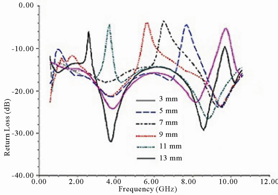
Figure 7. Simulated result of fourth iterative fractal antenna notch for various length of slot.
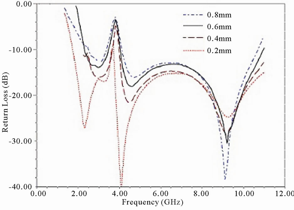
Figure 8. Simulated result of fourth iterative fractal antenna notch for various width of slot.
with slot length of 10 mm and width 0.4 mm.
6. Experimental Results
The proposed fractal antenna with U-type slot has been fabricated with optimized dimension 9.1 mm radius on substrate εr = 4.3, thickness 1.53 mm, GL = 18 mm, GW = 20.4 mm h = 0.4 mm, g = 0.5 mm, slot width = 0.4 mm and slot length 11 mm. The photograph of the proposed fractal antenna is shown in Figure 9. The simulated results of proposed fractal antenna with and without slot are shown in Figure 10. The antennas have been tested using vector network analyzer R&S ZVA 40. The experimental results of proposed fractal antenna without slot acquired from the Vector Network Analyzer exhibits the excellent ultra wide impedance bandwidth of 11.99 GHz (from 3.01 GHz to 15 GHz) corresponds to 132.49% impedance bandwidth for VSWR 2:1. The mea-sured return loss versus frequency of this fractal antenna has been shown in Figure 11.
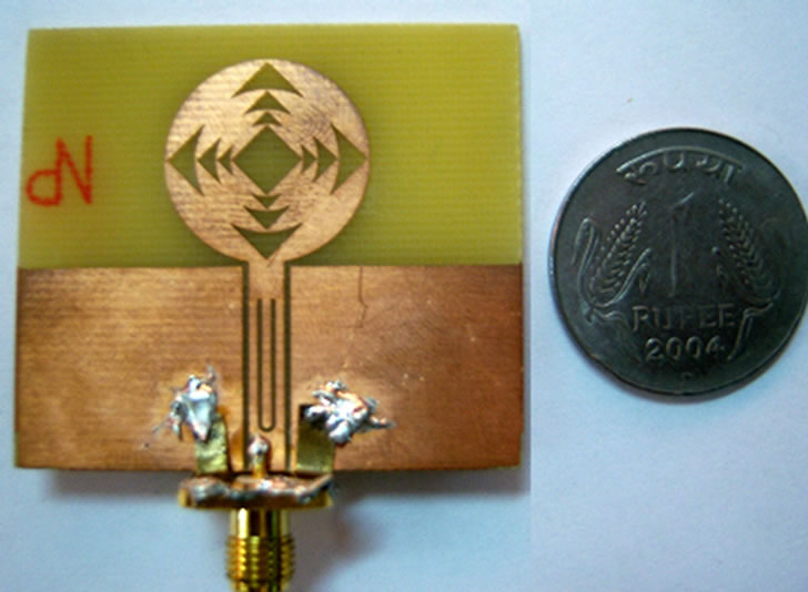
Figure 9. Photograph of the proposed antenna.
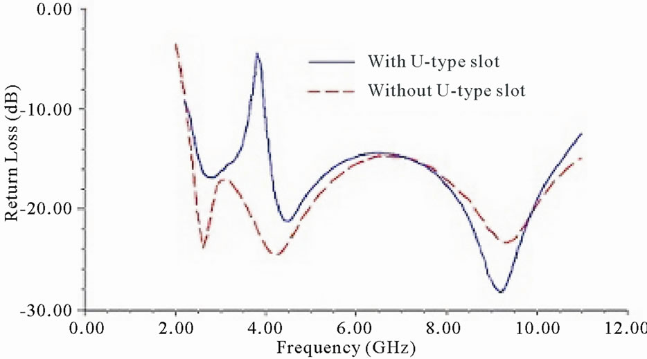
Figure 10. Simulated result with and without U-type slot.
The experimental result of circular fractal antenna with slot exhibits the UWB characteristic from 3.01 to 15 GHz except band-notched frequencies from 3.635 to 3.935 GHz. The return loss and VSWR versus frequency of this fractal antenna with band-notched have been shown in Figure 12 and Figure 13 respectively. It is observed that return loss is better at higher frequency in comparison to the return loss without notched-band. It is observed that simulated and measured results are slightly varies. This may be due to the tolerance in manufacturing, uncertainty of the thickness and/or the dielectric constant and lower quality of SMA connector (VSWR = 1.3). The differences between simulated and experimental value may also be caused by the soldering effects of an SMA connector, which have been neglected in our simulations.
7. Experimental Radiation Patterns
Radiation characteristics of the circular fractal antenna at operating frequency within the impedance bandwidth have also been studied. The measured radiation pattern in azimuth plane (H-plane) have been calculated at selective frequencies 4.2 GHz, 5.1 GHz, 6.0 GHz, 6.0 GHz and 7.2 GHz as shown in Figure 14. The radiation pattern in E-plane has also been measured at various selective frequencies 4.11 GHz, 5,025 GHz, 6.0 GHz and 7.05 GHz as shown in Figure 15. The H-plane radiation
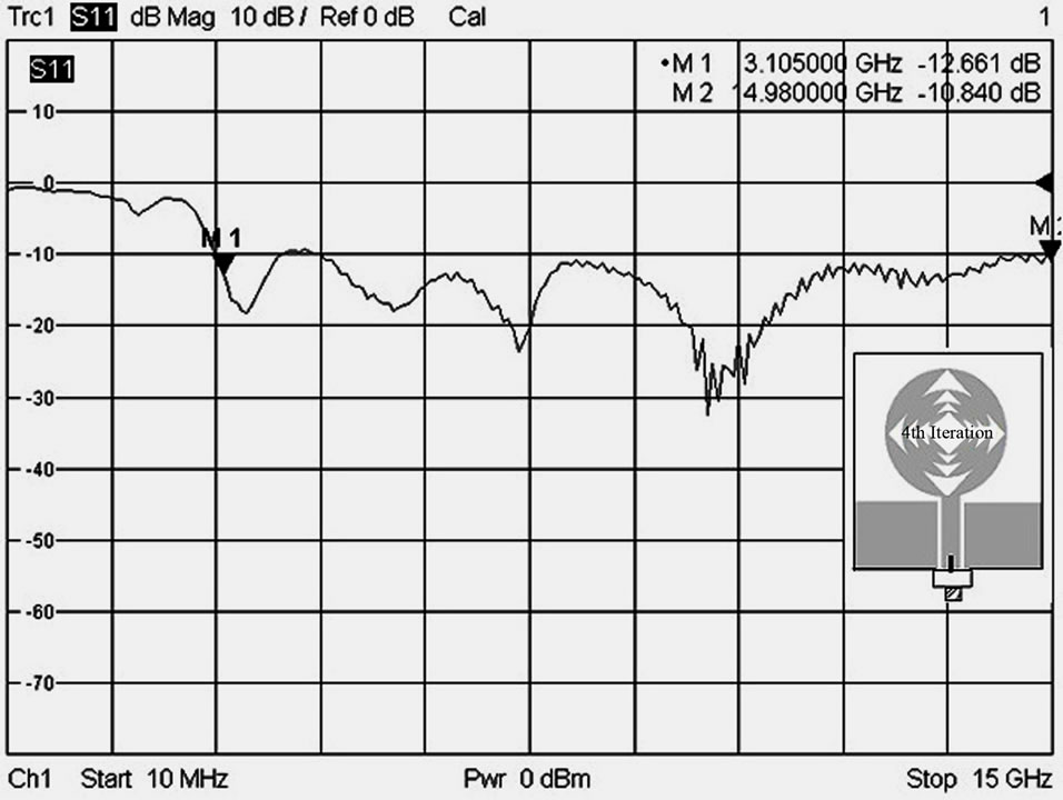
Figure 11. Experimental results proposed fractal antenna without U-type slot.
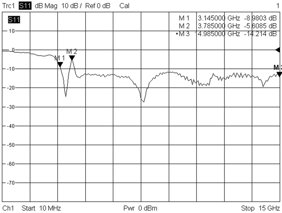
Figure 12. Experimental return loss versus frequency of fractal antenna with U-type slot.
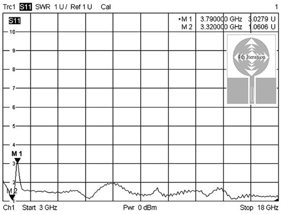
Figure 13. Experimental VSWR of circular fractal antenna with U-type slot.
patterns are almost omnidirectional, and the E-plane radiation patterns are like monopole radiation. It can be seen that the patterns of the proposed antenna are stable over the operating frequency range.
The proposed antenna gain in operating band meets the requirement for FCC defined UWB frequency band from 3.1 GHz to 10.6 GHz. It has been observed cross to copolarization ratio reduces at higher frequency. It has been observed that antenna gain is less than 5dBi in frequency range 3.1 GHz to 10.6 GHz. The gain drops significantly around −4.01 dBi at the band-notched resonant frequency as shown in Table 1. Such type of antenna is very useful for UWB communication system.
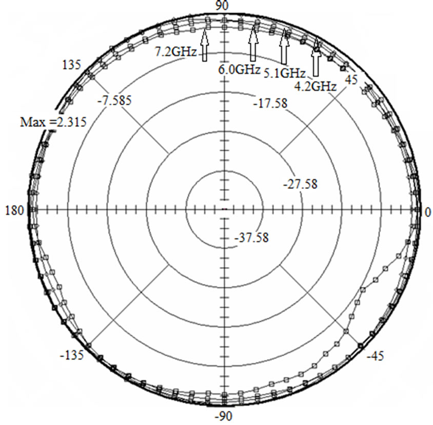
Figure 14. H-Plane Radiation Pattern of proposed fractal antenna at frequencies 4.2, 5.1, 6.0 and 7.2 GHz.
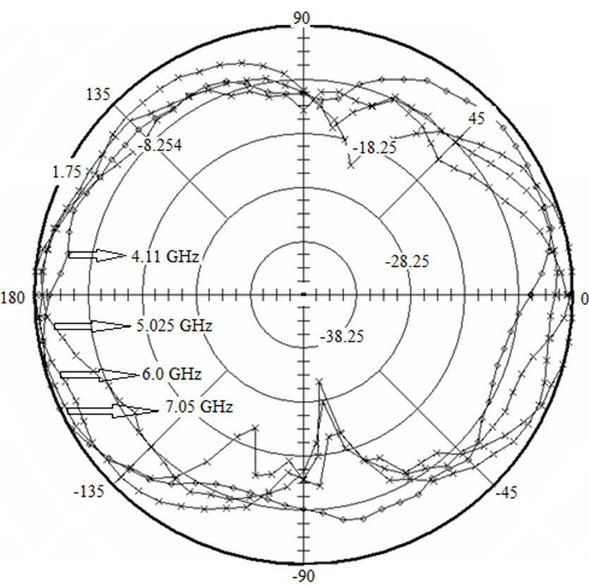
Figure 15. E-Plane Radiation Pattern of proposed fractal antenna at frequencies 4.11, 5.025, 6.0 and 7.05 GHz.
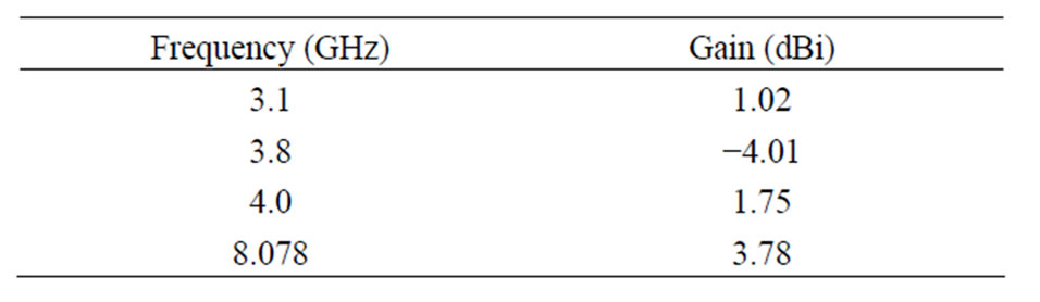
Table 1. Frequency versus gain (dBi).
8. Conclusions
In this paper, a new CPW-fed circular fractal antenna has been proposed with band-notched frequencies. Notched band is achieved to minimize the potential interference from external signals by introducing an U-shaped slot in 50 Ω feed line. The proposed monopole antenna has a wide operating frequency band of 3.01 GHz to over 15 GHz (VSWR < 2). It is observed that the radiation patterns of antenna in H-plane is omni-directional and E-plane is dipole-like radiation pattern over the entire operating bandwidth The proposed fractal antenna design is compact, low profile, and offers very large impedance bandwidth required for next generation UWB system. The use of coplanar ground plane makes the design conformal and more suitable for the miniaturized applications. Parametric studies are also presented to show the effects of different parameters on the antenna design. The measurement results have shown a good agreement with the simulation ones. Such type of antenna can be useful for UWB system as well as suitable for various military and commercial wideband applications.
9. Acknowledgements
The authors sincerely thanks to Vice Chancellor, Pro-Vice Chancellor, Dean, DIAT, Pune and for constant encouragement and support. Authors are thankful to all the research scholar of Microwave and Millimeter wave Antenna Lab and staff of for their support directly or indirectly.
REFERENCES
- G. R. Aiello and G. D. Rogerson, “Ultra-Wideband Wireless Systems,” IEEE Microwave Magazine, Vol. 4, No. 10, June 2003, pp. 36-47.
- H. J. Zhou, B. H. Sun, Q. Z. Liu, and J. Y. Deng, “Implementation and Investigation of U-Shaped Aperture UWB Antenna with Dual Band Notched Characteristics,” Electronics Letters, Vol. 44, No. 24, 2008, pp. 1387-1388.
- T.-P. Vuong, A. Ghiotto and Y. Duroc, “Design and Characteristics of a Small U-Slotted Planar Antenna for IR-UWB,” Microwave and Optical Technology Letters, Vol. 49, No. 7, 2007, pp. 1727-1731.
- R. Zaker, C. Ghobadi and J. Nourinia, “Novel Modified UWB Planar Monopole Antenna with Variable Frequency Band-Notch Function,” IEEE Antennas and Wireless Propagation Letters, Vol. 7, 2008, pp. 112-114.
- P. Dehkhod and A. Tavakoli, “A Crown Square Microstrip Fractal Antenna,” IEEE Antennas and Propagation Society International Symposium, Vol. 3, 2004, pp. 2396-2399.
- V. J. Lui, C. H. Cheng, Y. Cheng and H. Zhu, “Frequency Notched Ultra-Wideband Microstrip Slot Antenna with Fractal Tuning Stub,” Electronics Letters, Vol. 41, No. 24, 2005, pp. 294-296.
- W. J. Lui, C. H. Cheng and H. B. Zhu, “Compact Frequency Notched Ultra-Wideband Fractal Printed Slot Antenna,” IEEE Microwave and Wireless Components Letters, Vol. 16, No. 4, 2006, pp. 224-226.
- R. Kumar and P. Malathi, “On the Design of CPW-Fed Ultra Wideband Triangular Wheel Shape Fractal Antenna,” International Journal of Microwave and Optical Technology, Vol. 5, No. 2, March 2010, pp. 89-93.
- R. Kumar and P. Malathi, “Design of CPW-Fed Ultra Wideband Fractal Antenna and Backscattering Reduction,” Journal of Microwaves, Optoelectronics and Electromagnetics Applications, Vol. 9, No. 1, June 2010, pp. 10-19.