Energy and Power Engineering
Vol.5 No.3(2013), Article ID:31125,11 pages DOI:10.4236/epe.2013.53022
Influence of dc Component during Inadvertent Operation of the High Voltage Generator Circuit Breaker during Mis-Synchronization
1KOSTT—Kosovo Transmission System and Market Operator, Prishtina, Kosovo
2Faculty of Electric Engineering and Computer Sciences, University of Prishtina, Prishtina, Kosovo
Email: kadri.kadriu@kostt.com
Copyright © 2013 Kadri Kadriu et al. This is an open access article distributed under the Creative Commons Attribution License, which permits unrestricted use, distribution, and reproduction in any medium, provided the original work is properly cited.
Received January 22, 2013; revised February 24, 2013; accepted March 8, 2013
Keywords: High Voltage Generator Circuit Breaker; dc Component of Current; Asynchronous Connection; Delay Current Zero
ABSTRACT
This paper analyses the synchronization problem of a generator onto power system without satisfying synchronization condition. The main focus of the paper is on the impact of the dc component of the current in the high voltage circuit breaker during its close-open operating cycle. Using real time measurements of currents/voltages and angles during the close-opening cycle of high voltage generator circuit breaker and the impact of the dc component of current in context of interrupting large magnitude of current from the circuit breaker. In addition, the paper describes a study case model and the results of simulations performed using the software EMTP-ATP of an actual incident that occurred during the inadvertent synchronization of a large 339 MW, 24 kV generator to the grid.
1. Introduction
The synchronising of large generators into power systems results in electrical and mechanical transient processes such as voltage, rotor angle, frequency and torque. These electromechanical transient processes, cause an extreme oscillation between generator and-power systems, during an out-of-step condition which impose very high electromechanical stress on the generator.
According to the operations experience, the tolerances of those parameters between generator and power system have to be strictly satisfied in order that the process of synchronization can be carried out without excessively high stress.
During synchronization of the generator, it can happen that the generator could be connected to the network without meeting all of the synchronization conditions. This can happen for several reasons such a fault in the control systems, errors in synchronizing apparatus, defects of control cables, and human error. This paper describes the response of electromechanical quantities during synchronization of generator to the power system (asynchronous mode). The main focus of the paper is on the impact of the dc component of the current in the high voltage circuit breaker during its close-open operating cycle. The analyses of problem is based on real time measurements of quantities currents/voltages and angles during the close-opening cycle of high voltage generator circuit breaker and the impact of the dc component of current in context of interrupting large magnitude of current from circuit breaker. In addition, the paper describes a study case model and the results of simulations performed using the software EMTP-ATP of an actual incident that occurred during the inadvertent synchronization of a large 339 MW, 24 kV generator to the grid in which the synchronizing conditions were not met.
The time elapsed from asynchronous connection mode until the opening of the circuit breaker, is 150 ms. Prior to connection with the power system, the generator was operating under no-load conditions and waiting to meet the synchronisation condition. As a consequence, due to this asynchronous connection and the wide voltage angles between the generator and the power system, extremely high transient currents comparable to fault currents occurred. Under those circumstances, the protection relays in the generator and in the connecting circuit detect high magnitude transient currents and send a tripping signal to the high voltage circuit breaker.
Figure 1 a simplified scheme of generator connected to strong network is shown.
When the high voltage circuit breaker is closed the resulting electromagnetic torque will attempt to pull the rotor into synchronization with the power system, either slowing down or accelerating the rotor until the generator reaches its final equilibrium position which is defined by the steady-state rotor angle δs = 0 and the rotor speed ω = ωs.
It is assumed that just before the breaker is closed the generator is rotating at a speed ω close to synchronous speed ωs, and that the excitation is such as to produce an open-circuit terminal voltage Ef close to the system voltage. E' = Ef and angle of d = d’.
Therefore, the generator may lose synchronism with the rest of the system, when it makes asynchronous rotations at a slip frequency, which is a few hertz above/below synchronous speed. If the frequency increases, than the Primary regulator of Turbine acts too in order to stabilize in the new point of static characteristic of generator and vice versa [1].
2. Asynchronous Connection of Generator to Power System and Impedance Loci during Power Swings
Out-of-step tripping may be installed either as part of the generator protection system or as part of the transmission network protection. When installed in the generator protection system they isolate the generator in the event of asynchronous operation. Out-of-step tripping relays can also be used inside the transmission network in order to split the system at predetermined points should asynchronous power swings occur [2].
Out-of-step blocking relays are installed in the transmission network in order to block the operation of distance protection relays during occurrence of power swings. Because of impact on overall power system operation there are cases when this function is blocked or a delay applied to the tripping signal.
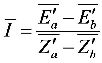
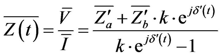
However, in practice, some relays are set to detect power swings in the grid. A Power swing is detected by the relay as a change in the apparent measured impedance. The effect of power swings on the impedance locus can be analyzed using the simple equivalent circuit shown in Figure 2 in which two equivalent synchronous generators are linked via impedances Za and Zb. Voltage and current is measured by the relays and the apparent impedance is calculated from the voltage-current ratio.
 and
and  (1)
(1)
E'a, E'b are the magnitudes of the equivalent transient emf-s, Z'a, Z'b are the equivalent transient internal impedances of transmission network and the generators [3]. If the magnitude of emfs is assumed to be constant, then the apparent impedance measured by the relay is:
 (2)
(2)
where 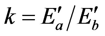 and d’ is Transient power angle of power system.
The Equation (2) determines the locus on the complex plane of all points of apparent impedance measured by relays. The power swing is detected by monitoring of the speed at which the impedance locus approaches the outermost characteristic of the distance relay, usually the fault detection zone.
High Current Interruption with AC Generator High Voltage Circuit Breaker
Short-circuit current interruption in an AC circuit by an

Figure 1. Simplified scheme of generator connected to strong network.
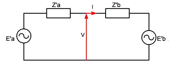
Figure 2. Equivalent circuit of the system with a relay point.
high voltage circuit breaker, is described in the international standard for circuit breakers IEC 62271-100. The circuit breakers that connect generators to the high voltage network in some circumstances are subject to more extreme stresses during faults than are, for example, line circuit breakers. They require to have certain features that distinguish them from other classes of circuit breaker for other duty. As a consequence, the specification of a generator circuit breaker is essentially defined by the system source fault conditions. A significantly high level of dc component that cause high asymmetrical fault current is typically present in the generator than is found in network lines, which can cause problems/challenges in current interruption difficulties to interrupt the current. The IEC 62271-100 [4] and IEEE C37.013-1997 [5] standard describe the particular conditions of current asymmetry that can occur during short circuit and out-ofphase conditions.
In this paper, the behavior of a generator during asynchronous connection of the generator to the power system is analyzed, with particular reference to the dc component of the current to be interrupted. The analysis also examines the possibility to apply a time delay to the protection relay trip signal, allowing time for the dc component of current to decrease in order to successfully interrupt the fault current. According to the standards the interruption of current by a high speed circuit breaker should be completed in not more than 40 ms (time of circuits is 20 ms and 15 ± 5 ms for the extinction of the arc [6,7]. If the current is not successfully interrupted after the circuit breaker contacts are opened, for the dedicated time, then the circuit breaker may suffer serious damage or explosion. In our case, due to this accident, the protective relays attempted to open the generator circuit breaker after asynchronous connection. However, in this case the high level dc component in phase L1 led to a situation where the current did not pass through zero for a relatively long time. As a result, the circuit breaker in one chamber, were damaged.
The following is analyzed the presence of dc component of current including equation of that current. The dc component decreases exponentially depending on a time constant. From the Equations (3) and (4) of dc component is found the critical time that is considered enough to decrease the dc component, in order to successfully open the circuit breaker.
3. Analysis of Actual Incident, including the Sequence of Events during the Asynchronous Connection of Large Generator in 400 kV Network
Figure 3 is shown single line diagram of connection of large generator rated power 339 MW to power system.
Based on the real time measurements it is deduced that the closing order to connect the generator to the network is done in instance of wider angle on approximately 114˚. As a result, the swing of current and oscillating of active and reactive power between the generator and power system occurred.
The diagram below, Figure 4 shows the phasor diagram of generator and power system voltages, a few milliseconds before circuit breaker closing. The phasors UL1, UL2, UL3 represent generator voltages and the voltage phasor Usyn 2 represents the reference voltage of network, which is used for synchronization of the generator. From the phasor diagram in Figure 4 it is clear that the angle between the phasor voltages of the network and the generator is close to 114˚. The magnitude of the slip frequency at the time of synchronizing is unknown.
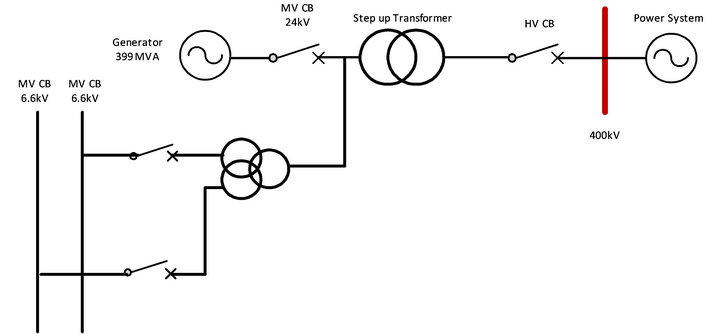
Figure 3. Single line diagram Generator and step up transformer connection to grid. Data of generator: Sn = 399 MVA, Un = 24 kV, Step up Transformer 24/400 kV, Dy5.
Fifty milliseconds later, when the circuit breaker is closed, the phasors of generator and power system align as shown in Figure 5.
Figures 6 and 7 illustrate the generator currents, in phases L1, L2 and L3, at the post-synch swing condition. As the generator is connected to a strong system, the initial stator currents will be up to seven times the rated current of the generator step up transformer. The resulting current, after inadvertent connection of the generator into the network, has an ac component and a dc component. The magnitude of the dc component is different in each phase with phase L1 having the highest value. The value of this dc component depends on the instant when the fault occurs and the relative displacement of the generator and network phasors at synchronization.
The transformer unit protection and the line protection, in response to those currents, have triggered and tripped the circuit breaker. Thus for the time 100 ms the dccomponent of phase L1 has a very high value. As a consequence, the ac component is fully offset and has nonzero crossing during this time which the necessary condition for the arc to be extinguished. According to the IEC standard, the high voltage circuit breaker is designed to extinguish the arc within a time of 15 ± 5 ms, but the current should pass the zero after 1 cycle at frequency 50
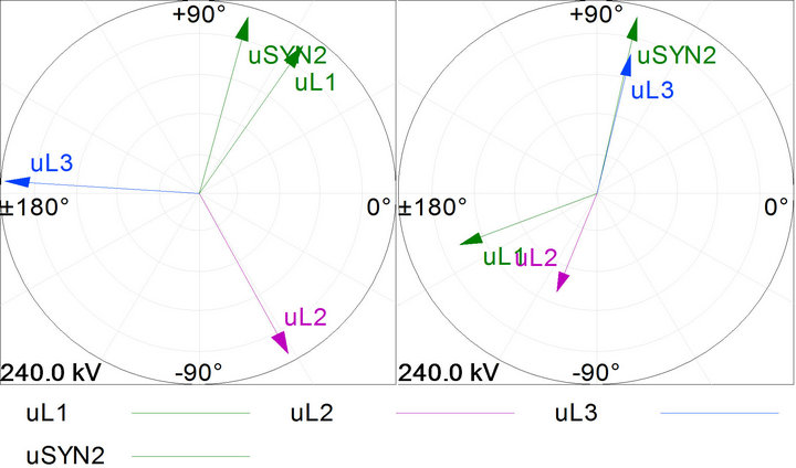
Figure 4. Phasor diagram of voltages just prior to closing of the generator circuit breaker to the network.
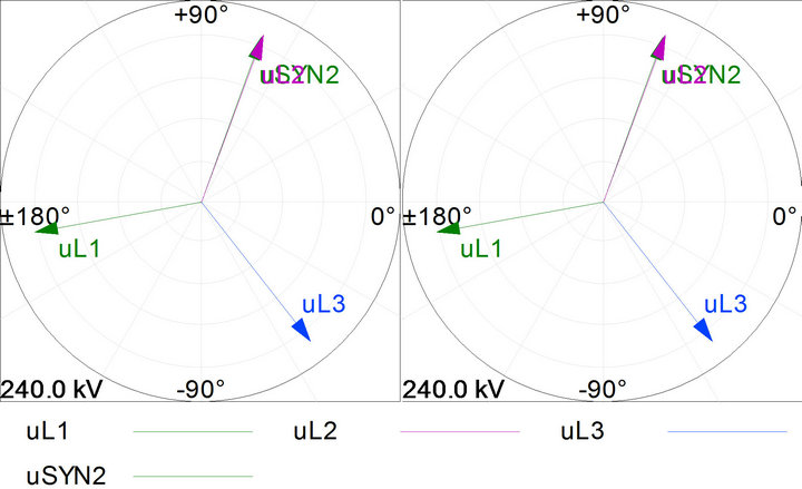
Figure 5. After the generator is connected to the HV grid.
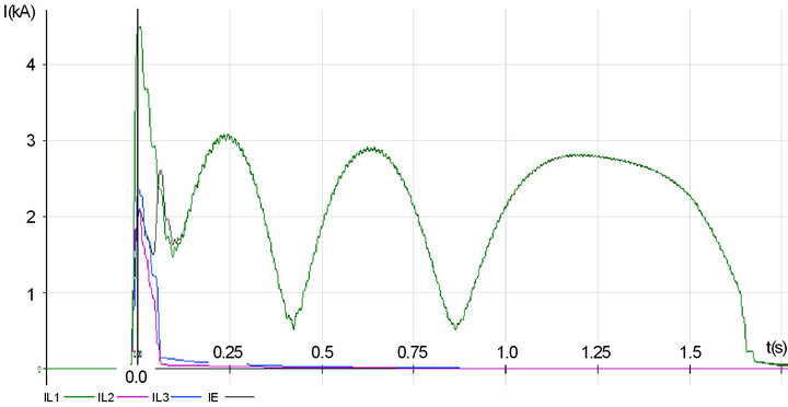
Figure 6. RMS Values of three phase current.
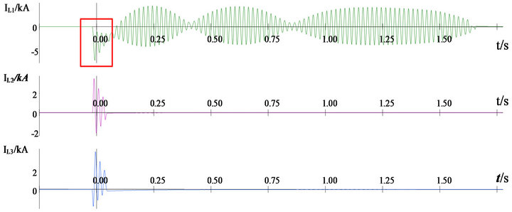
Figure 7. Oscillogram of currents on high voltage 400 kV of generator step-up transformer during close-open of circuit breaker.
Hz. As seen in the oscillogram (Figures 6-8), the current in phase L1 did not cross zero for 100 ms. The prolonged electrical arc caused damage to one chamber of the SF6 circuit breaker Live Tank type. The voltage across the open contacts is high enough to cause more arc flash overing between the generator’s circuit breaker contacts. Also the post-arc recovery voltage is higher than the circuit breaker rated withstand voltage consequently the arc reignites with 400 to 600 msec. evidence.
In the Figure 7 is highlighted the time of phase L1, during which asymmetric currents did not pass into zero.
Also is indicative that the peak value of power after closing of circuit breaker because of oscillation of generator with power system is 940 MW. The oscillation of active and reactive power of generator is shown in Figure 9.
As a result of synchronization the rotor’s initial increasing lagging angle slowed down, stopped (i.e fgen = fsys), reversed direction (i.e., fgen > fsys and Pelectric-motoring > Pmechanical-speed,no-load) and then begin to increase in the leading direction, shrinking the displacement between the unit and the system reference vectors. The synchronous equilibrium point is defined as the state in which the unit rotor angle matches the system angle and no power exchange take place (i.e, P = 0, except for the power needed to overcome generator losses)
The dc component of the current decreases exponentially with a time constant which in this case is approximately 72 ms. When asymmetrical current is not passing
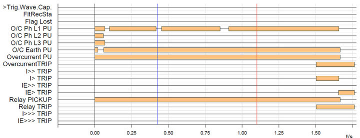
Figure 8. Arc ignition and act of relay during close-open and flashover in circuit breaker.
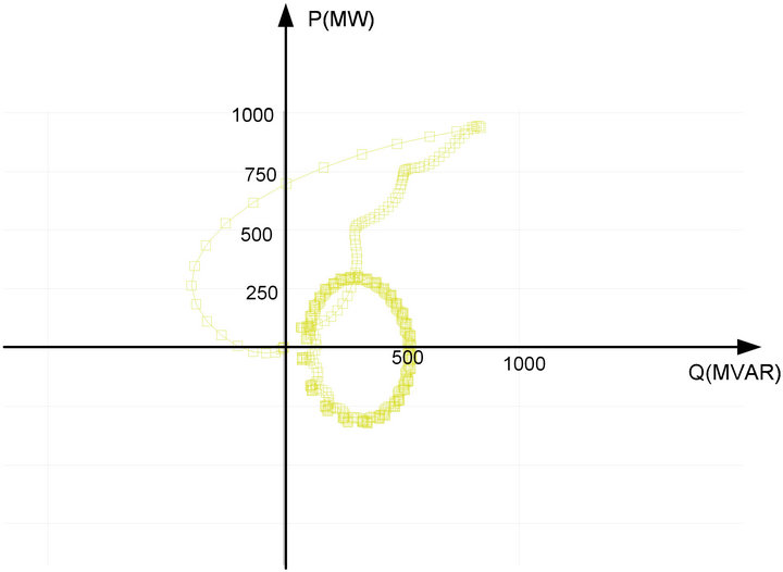
Figure 9. Locus of power exchange between generator and network.
through zero, the successful extinguish of electrical is difficult. The electric arc is extinguished at a zero current. This helps the ac circuit breaker to interrupt the current between contacts. The magnitude and duration of the dc component is a very important and should take into consideration during the specification of high voltage generator breakers. In Table 1, the values of dc and ac of current components during the initial 150 ms are listed.
The dc component (%) is calculated based on IEC 62271-100 [2] respectively Figure 10 and using Equation (3).
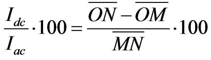 (3)
(3)
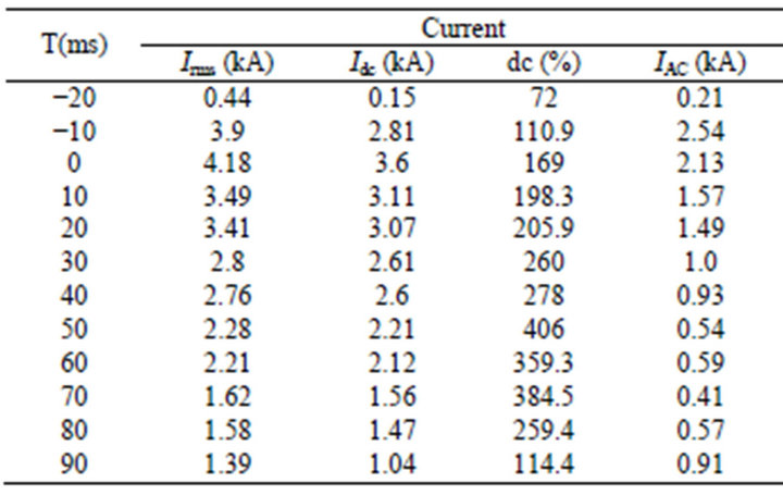
Table 1. ac and dc component of current depending on time.
From the instant when the circuit breaker contacts close, the dc component increases to a maximum of Idcmax = 3.11 kA within 30 ms. After 110 ms, the value of dc component has decreased to 47.2% of the ac component, and as a consequence, the ac current crosses zero for the first time. The Figure 11 shows the respective changes dc and ac component of current and the total current that passes through circuit breaker.
The dc component of current based in Figure 12 is modeled by equation:
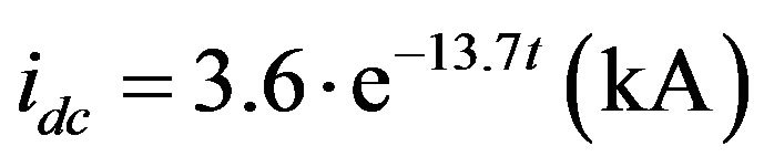 (4)
(4)
Figures 13 and 14 show the damaged main contact in one chamber of the 400 kV Generator circuit breaker. The insulation of one pole of the circuit breaker is destroyed as consequences the arc flashing appears at
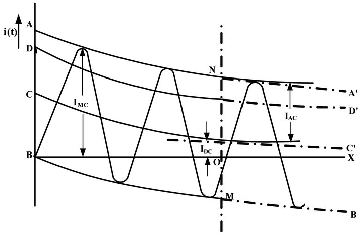
Figure 10. IEC 2271-100[1]. Determination of short-circuit making and breaking currents, and of dc component percentage [2].
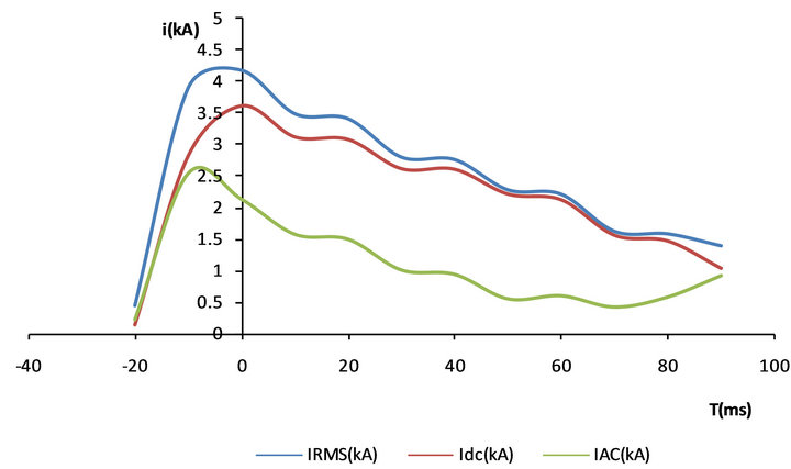
Figure 11. RMS current and ac and dc component of current.
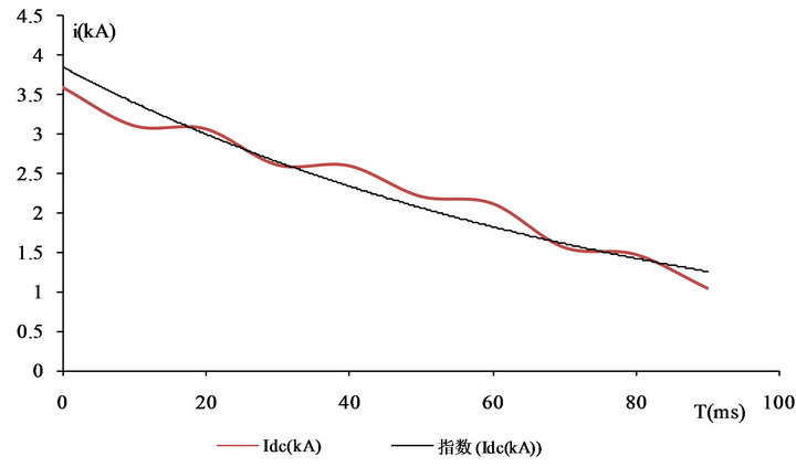
Figure 12. Exponential functionof dc component of current.
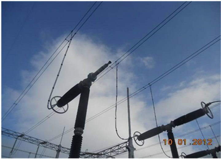
Figure 13. Live tank circuit breaker.

Figure 14. Circuit breaker contacts showing damage caused by electric arc.
every 400 to 600 msec. Due to the flashover in one pole of the circuit breaker, the current waveform as shown in Figure 7 is appeared. Such a current waveform causes difficulties for the relay protection to trip the breaker. The relay protection is set up for permanent faults. The relay cannot detect this fault condition, because the flashover current decreases faster than the time the relay needs to complete its trip operation [8].
The best way to isolate such faults is using a breaker failure protection scheme [9], but this is usually set up as: the flashover should be detected by a generator protection relay, which would initiate the breaker failure function. The Breaker failure current detector must be set with sufficient sensitivity to detect the flashover condition. The circuit breaker tripping time when initiated by breaker failure protection is typically 150 - 200 ms [10].
4. Study Case Simulation Using ATP Software
The test of behavior of generator that is connected to power system without satisfied synchronization condition is done with ATP software. Validation of the program is done by comparison of current and voltage waveforms obtained by measured during real case recorded by relay.
a) Case of IEEE C37.013-1997 Annex A: 21 kV, 588 MVA, Step-up Transformer 21/550 kV, Yd5 and System source short-circuit current on high voltage side of generator step-up transformer 40 kA, Time constant X/wR of the high-voltage system 45 ms. In the Figure 15 is shown IEEE model of large generator connected to strong network. The following Figures 16-21, represent the simulation results of currents during synchronisation for different displacement angles between generator and power system.
b) Real Case: Generator rated Power Sn = 399 MVA, 339 MW, 24 kV, Step-up Transformer 24/420 kV, Yd5 and System source short-circuit current on high voltage side of generator step-up transformer 25 kA, Time constant X/wR of the high-voltage system 45 ms. The following Figures 22-26, represent the simulation results of real case study of currents during synchronization for different displacement angles between generator and power system.:
5. Conclusions
Based on the measurements of an actual incidents, and analysis using ATP software, the following is concluded:
• High voltage circuit breakers used at generators, have some special requirements compared to those at other locations. Specifically they must be able to interrupt fault currents which do not have any zero crossing for several cycles.
• In the particular incident reported, the presence of a large dc component of current prevented the current from crossing zero for several tens msec, resulting in serious damage to one pole of circuit breaker.
• Fast tripping relay protection at generator circuit breakers is not advised in all practical circumstances.
• In the incident reported here, delaying the relay trip order to the high voltage circuit breaker for 70 ms would have been beneficial, allowing the dc component of current to decay sufficiently to give a zero

Figure 15. Circuit used for calculations.
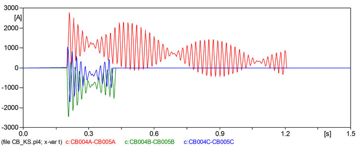
Figure 16. Simulation of Synchronization of generator into power system on wide angle 30˚.
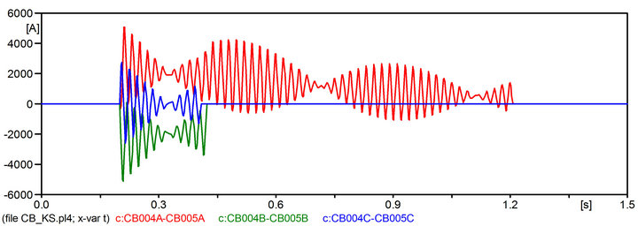
Figure 17. Simulation of Synchronization of generator into power system on wide angle 60˚.
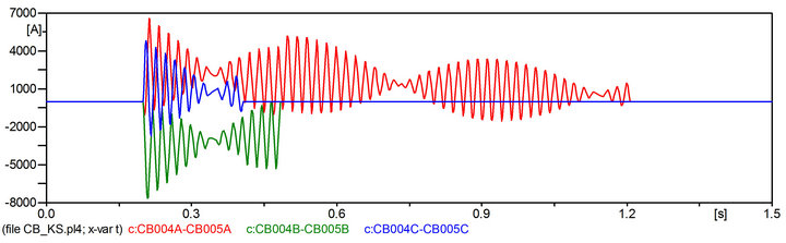
Figure 18. Simulation of synchronization of generator into power system on wide angle 90˚.
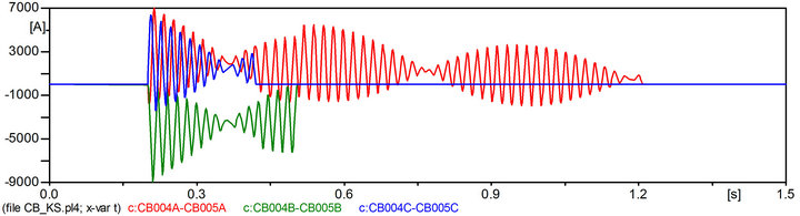
Figure 19. Simulation of synchronization of generator into power system on wide angle 110˚.
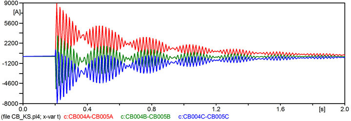
Figure 20. Simulation of synchronization of generator into power system on wide angle 114˚.
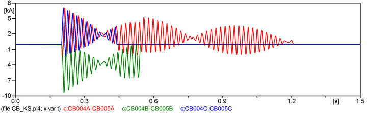
Figure 21. Simulation of synchronization of generator into power system on wide angle 120˚.
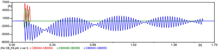
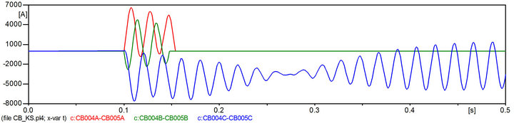
Figure 22. Simulation of synchronization of generator into power system on wide angle 90˚.

Figure 23. Voltage waveform for simulation case at angle 90˚.
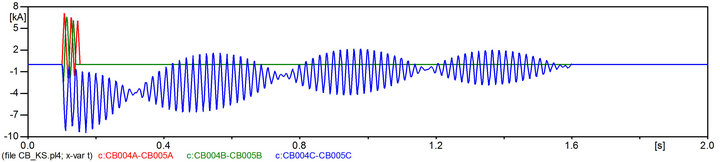
Figure 24. Real case: current waveform at high voltage network 400 kV during synchronization on wide angles differences 114˚. Real case.
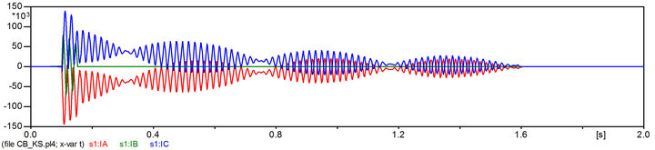
Figure 25. Current waveform at medium voltage network 24 kV on terminal of generator during synchronization on wide angle 114˚.
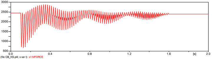
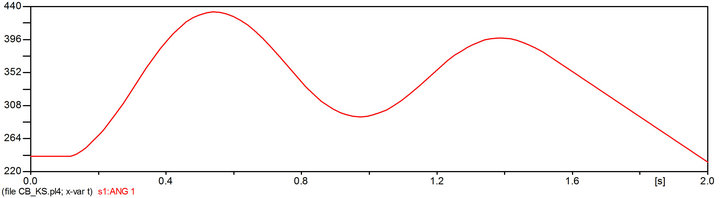
Figure 26. Angle oscillation.
crossing for current interruption without causing without damageto the circuit breaker.
• This means that a delay of 70 ms has also to be applied in Busbar protection schemes, implying that all busbar faults will be cleared with added delay.
• The consequences of adding this time delay should be thoroughly analysed in the context of its effect on the rest of the power system, including transient stability.
6. Acknowledgements
We would like to express our gratitude for sponsor of this paper, company KOSTT (Transmission System Operator and Market Operator in Kosovo).
REFERENCES
- P. Kundur, “Power System Stability and Control,” McGraw-Hill, Inc., Boston, 1994.
- J. L. Blackburn, “Protective relaying Principles and Applications,” Taylor & Francis Group, LLC, London, 2007.
- J. Machowski, J. W. Bialek, J. R.Bumby, “Power System Dynamics and Stability,” 2nd Edition, Jon Wiley & Sons Ltd., Hoboken, 2008.
- IEC 62271-100-High-Voltage Alternating-Current CircuitBreakers, CEI/IEC 62271-100:2001+A1:2002.
- IEEE Standard for AC High-Voltage Generator Circuit— Breaker Rated on a Symmetrical Current Basis, Revision of IEEE Std. C37.013-1993.
- M. Abdel Salam, “High Volatge Engineering Theory and Practices,” Marcel Dekker, Inc., New York, 2000.
- KOSTT, “Electrical Equipment Code,” 2nd Edition, KOSTT, Kosovo, 2009. www.kostt.com
- M. A. Ibrahim, “Disturbance Analyses for Power System,” Jon Wiley & Sons, Inc., Hoboken, 2012.
- Working Group, B5.04 International Guide on the Protection of Synchronous Generators, 2011.
- KOSTT, “Grid Code,” 2nd Edition, KOSTT, Kosovo, 2010. www.kostt.com