Communications and Network
Vol.2 No.2(2010), Article ID:1864,12 pages DOI:10.4236/cn.2010.22018
PBB Efficiency Evaluation via Colored Petri Net Models
Odessa National Academy of Telecommunications, Odessa, Ukraine
E-mail: vorobiyenko@onat.edu.ua, k.guliaiev@gmail.com, zsoftua@yahoo.com, tishtri@rambler.ru
Received January 6, 2010; revised February 5, 2010; accepted March 1, 2010
Keywords: PBB, E6, Colored Petri Net, Simulation, QoS
Abstract
Basic components of Provider Backbone Bridge (PBB) network models were constructed: PBB interior switch, PBB edge switch—with the dynamic filling up of address tables. The modeling of PBB networks was implemented. The results of simulation reveal definite imperfections of PBB technology caused by the broadcasting and sensitivity to the ageing time of the address tables’ records, which complicates the guaranteeing of a given QoS. The preliminary comparison confirms definite advantages of E6 addressing before PBB.
1. Introduction
Technology of Provider Backbone Bridge (PBB) [1] is aimed to the construction of networks entirely on the base of Ethernet. Corresponding standard IEEE 802.1ah [2], which development was started in 2005 has been prepared in a draft variant, while companies have already started the issuing of PBB switches and providers have started their exploiting. British Telecom has chosen switch-router Nortel Metro 8600 and Metro Ethernet Services Unit of 1850 series as Ethernet components of network in the project 21CN («Network of 21 Century»). The delivery of superproductive PBB switches BlackDiamond 20808 of Extreme Networks Company has been started to Russia.
With the advent of 1 Gbps and 10 Gbps Ethernet standards, new opportunities of Ethernet technology mass employment in provider backbone networks have been opened, but 802.3, 802.1D technology has a series of disadvantages regarding scalability, quality of service, manageability, which a new series of IEEE standards were developed to overcome: 802.1Q—virtual networks, 802.1QinQ—multilevel virtual networks, 802.1ad—provider bridges, 802.1ah—backbone provider bridges, 802. 1ag—networks management, 802.1Qay–traffic engineering. Mentioned standards provide the Carrier Ethernet concept to substitute SDH, as well as IP-MPLS solutions in backbone networks, though IETF undertakes active attempts of MPLS and PBB standards integration in virtual private service VPLS [3].
In [4,5], an alternative solution was suggested for Ethernet scalability under encapsulation IP-Ethernet via uniform network hierarchical addresses E6, which are situated into MAC-addresses fields of Ethernet frames. While PBB supposes the enlargement of frame header length adding backbone switches MAC-addresses pairs, Е6 has definite advantages because of annulment TCP, UDP, IP protocols, as well as corresponding packet headers and address mapping protocols ARP/RARP. Models of Е6 networks presented in [6], creates the basis for comparison of two technologies. However, fullfledged comparative analysis is possible under the construction of rather detailed PBB network models and modeling of IP-Ethernet encapsulation processes.
The purpose of the present work is PBB networks basic components construction in the form of colored Petri nets in the environment of simulating system CPN Tools [7], as well as an evaluation of PBB technology efficiency via PBB networks modeling.
2. The PBB Technology Overview
IEEE 802.1ah frame [1,2] encapsulates IEEE 802.1QinQ and IEEE 802.3 frames. IEEE 802.1ah frame header (Figure 1, Table 1) contains C-MAC—customer addresses (C-DA, C-SA) and B-MAC—backbone addresses (B-DA, B-SA). Moreover, the recurring encapsulation of PBB frames is stipulated for multilevel backbone networks creation.
Abstracting from header fields of virtual networks, let us consider the interaction of address fields on the example of network shown in Figure 2. Let host X with MAC-address AX send a frame to host Y with MACaddress AY. The corresponding 802.3 (802.1ad) frame is created with C-DA = AY, C-SA = AX. The frame is delivered to the nearest PBB edge switch PBBX with MAC-

Figure 1. Format of IEEE 802.1ah frame header.
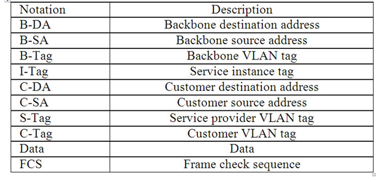
Table 1. Description of IEEE 802.1ah frame header fields.
address ABX. By the destination address AY (using address tables), switch PBBX determines address ABY of PBB backbone switch PBBY, which the network containing Y is attached to. PBBX encapsulates 802.3 frame into 802.1ah frame with B-DA = ABY, B-CA = ABX and sends the frame into backbone. PBB backbone switches use only the pair of addresses B-DA, B-SA for the delivery of the frame to PBB edge switch PBBY. At the frame receiving, PBBY extracts the encapsulated 802.3 (802.1ad) frame and implements the frame delivery to host Y using the pair of addresses C-DA, C-SA.
Passive listening is used for the filling in address tables. If the destination address is unknown then broadcasting is implemented. Tree-like network is represented in Figure 2; the standard implies modified spanning tree algorithms application for the work on non tree-like topology.
The advantage of PBB technology is the backbone performance increase due to considerable reduction of address table size for PBB interior switches, which contain B-MAC addresses only. But the functioning of PBB edge switches, which implement the mapping of C-MAC addresses into B-MAC addresses and encapsulation of frames, is getting complicated. Usual 802.1D switches work at the network periphery.
3. Scope of the Model
Simulating system CPN Tools [7] was chosen for the construction of models; it was developed in Aarhus University, Denmark and uses the language of colored Petri nets [8] for models description. In Odessa National Academy of Telecommunications named after A. S. Popov, the library of the model components was created for Ethernet, IP, MPLS, Bluetooth, E6 networks as well as the library of measuring fragments for the networks performance and QoS evaluation [6,9-12].
In the present work at the PBB technology modeling, only address part of the frame header without virtual network tags was taken into consideration; moreover, only one level of provider bridges hierarchy and tree-like structure of the network were considered. Modeling of virtual networks tags, multilevel hierarchy and spanning tree algorithms of provider bridges are the directions for future work. Moreover, the investigation of fully connected network structures (without the division into virtual private networks) similar to the Internet relates to the purpose of consequent comparative analysis of PBB and E6 regarding advantages of usage in world-wide networks.
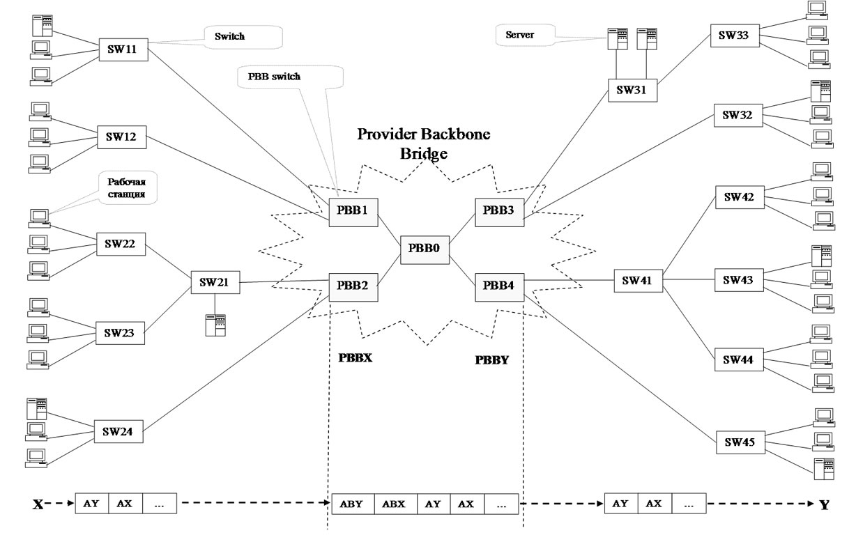
Figure 2. An example of PBB network.
The following components were constructed for the modeling of PBB networks:
—model of interior PBB switch SWBm;
—model of edge PBB switch SWBm-n;
—model of 802.1D (traditional) switch SWn;
—models of terminal (subscriber) equipment: WS— workstation, MWS—measuring workstation, S—server.
Variables m, n denotes the quantities of B-ports and C-ports correspondingly.
At the SWn switch model construction (model of portport), as the base was taken the model [9] with dynamic running of switching tables modified regarding only microsegmented Ethernet usage and running separate queues of frames on ports. Model of interior PBB switch SWBm (model of port-PBBport) has distinctions regarding the backbone MAC-addresses processing. The model of edge PBB switch SWBm-n (models of ports-cport, bport) is the most sophisticated as it provides the mapping of customer C-MAC addresses into backbone B-MAC addresses as well as the broadcasting of two corresponding kinds.
At the traffic modeling, the concept of client-server interaction was used and corresponding components[9,10], which were supplied with counters for the useful and broadcasting traffic estimation as well as various kinds of random functions distribution lows. Note that at the large scale backbones modeling, it is advisable to use the flow traffic models [6] to abstract from the detailed description of the network periphery.
The components were used for the network (Figure 1) model construction and analysis; the corresponding main page of the model was named Network. Measuring workstations MWS [9,10] provide the evaluation of network response time; counters represented by fused places shifted to the main page of the model provide the evaluation of useful and broadcasting traffic.
4. Network Model
The network model shown in Figure 2 is represented by the main page of the model Network in Figure 3 and by the models of used components in Figures 5-9. The main page is constructed on the base of network structure scheme direct mapping principle. One 4-ports interior PBB switch PBB0 of the kind SWB4 and four 3-ports
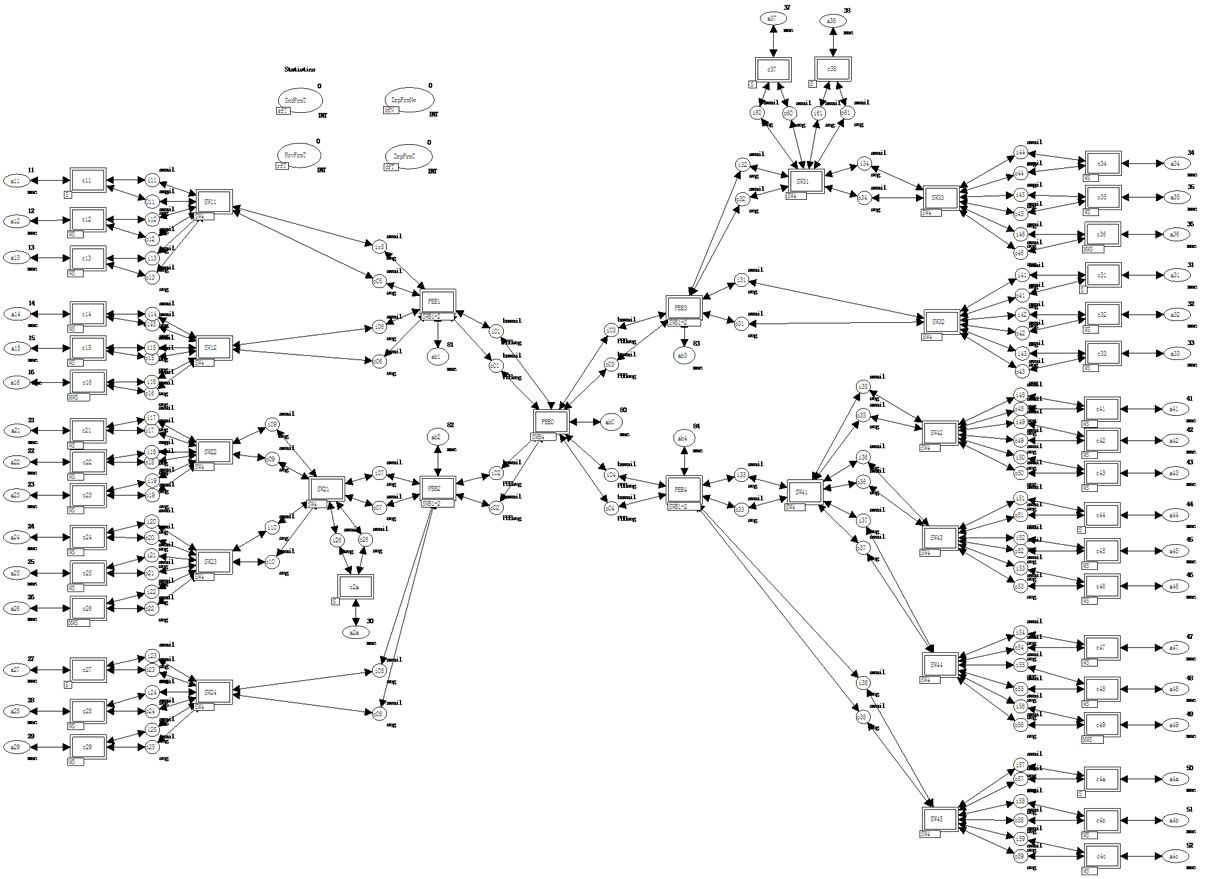
Figure 3. Model of network (Network).
edge switches PBB1-PBB4 of the kind SWB1-2 with one B-port and two C-ports were used for modeling of PBB backbone. 14 4-ports switches of the kind SW4 were used for the periphery networks modeling. The model of terminal (subscriber) equipment is represented by 24 worktations WS, 4 measuring workstations MWS and 8 servers S.
The descriptions of basic data types (color sets) and model functions are represented in Figure 4. In the main page of the model the following types of places were used: mac—MAC-address, seg—usual segment, PBBseg —PBB segment; as the indicator of segments availability the constants avail, bavail for usual and PBB segments were used correspondingly.
In the main page of the model, C-MAC addresses of customer equipment are pointed out in places a11-a4c and B-MAC addresses of PBB-switches—in places ab0- ab5; MAC addresses are represented by integer numbers, which does not bound the generality if for instance only the last byte of MAC-addresses coinciding in the first 5 bytes is considered.
Each port of switches is represented by the pair of places modeling the full-duplex mode of work. Place ik—input channel of k-th port; place ok—output channel.
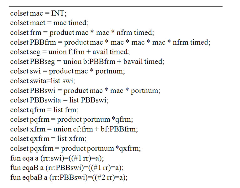
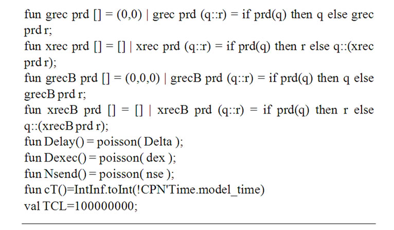
Figure 4. Description of basic data types and functions.
The connection of the equipment according to the network structure scheme is implemented by the fusion (merging) of input and output places of ports. Note that at the two switches connecting, the input channel of one is fused with the output channel of the other one and vice versa; names of ports places are chosen regarding the switch situated more closely to PBB0.
Moreover, the fused places are shifted to the main page of the model for the traffic evaluation: SndFrmT of the kind sfT—counter of sent frames, RcvFrmT of the kind rfT—counter of received frames, DrpFrmNw of the kind dfN—counter of frames dropped in network, DrpFrmT of the kind dfT—counter of frames dropped in terminal equipment.
5. Networking Equipment Models
The networking equipment models are represented by the early mentioned switches models of thee different kinds: SW4, SWB4, SWB1-2. The switch model layout has minor peculiarities and is considered on the example of 802.1D (traditional) switch SW4 shown in Figure 5. The model is assembled by cloning required number of ports models port.
Each port is identified by unique number (myport*). The shared data stored in switch memory are used for the interaction of ports. As the most simple, the store-andforward architecture with obligatory buffering of frames is considered. The frame arrived to the input channel of port A, is stored in the buffer Buf; meanwhile, using the switching table SwT the number of the port B is determined for the frame forwarding. If the frame destination address is not mentioned in the table then the switch implements the broadcasting—the frame is forwarded to all the ports of the switch save the port A. The output channel of the port B extracts the frame out of the buffer and transmits it into corresponding segment. The total quantity of switch ports nport and the number of own port myport* are used in the broadcasting. Place timer contains MAC-addresses, pointed in the table SwT together with time stamps (data type mact); transition ClrSwTa provides the erasing of the corresponding record of the table SwT after the elapsing of ageing time interval (constant TCL); recursive function xrec implements the erasing of the record out of table represented by variable x; function eqa implements the addresses comparison. Port implements the passive listening of traffic (sender addresses) with the aim of filling in the table with new records.
Note that in the buffer Buf of the type qpfrm, separated FIFO queues of frames on switch ports are organized according to the standards. The initial marking creates 4 empty queues (lists); the header of a queue is equal to the number of corresponding port.
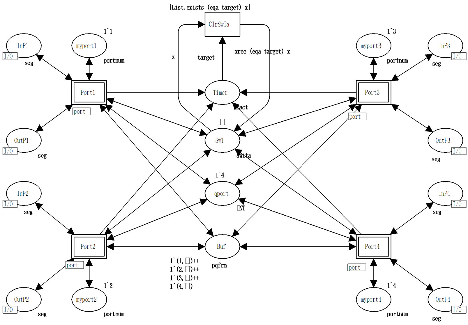
Figure 5. Model of switch 802.1D (SW4).
5.1. Switch Port Model
The model of 802.1D switch port is represented in Figure 6. The type seg is used for the description of Ethernet segment channel, which can be either free (the constant avail) or busy with the frame f transmission. The type frm is used for the frame f description consisting of sender address src, destination address dst and frame number nf (the description abstracts from the frame content). The type swita describes the switching table as a list of records swi consisting of destination address dst and port number pnum. Recursive function grec extracts record from switching table. The type pqfrm of the buffer Buf describes queues qfrm enumerated on ports of frames. Input and output arcs inscriptions, which will be described further, realize FIFO discipline of queues.
A frame arrives to input channel of port PortIn; its sender address src can be either new (transition NewSrc) or known (transition OldSrc). Transition NewSrc fills in the switching table with a new record, which contains sender address src and port number m (current port of switch). The frame is put into auxiliary place Aux1, then the frame destination address dst is analyzed, which can be either a new (transition NewDst) or known (transition OldDst). Transition OldDst puts the frame into the buffer Buf, the queue corresponds to the determined output port number. Transition NewDst puts the frame into auxiliary place Aux2 and starts the broadcasting process. Place pnum is used for sequential (i: = i + 1) numeration of broadcasting ports. Transition BroadC implements the broadcasting until the numbers of all the ports are exhausted (i ≤ q); then at (i > q) the transition clean is started, which cleans auxiliary places and returns the availability indicator avail into segment. The condition (i<>m) in the inscription of broadcasting arc BroadC→ Buf excludes the broadcasting into own port.
Output channel of a port extracts frames from the buffer Buf redirected into the current port (m) and transmits them into segment via transition Out, which waits and deletes the indicator of segment availability avail.
Let us consider the work with queues of frames in the buffer Buf more closely. The frame insertion is implemented into the tail of port i queue; for that the corresponding queue is extracted from place Buf via arc inscription (i,qu), then the frame f is inserted into the tail of the queue via arc inscription (i,qu^^[f]). The frame extraction is implemented from the head of port m queue;
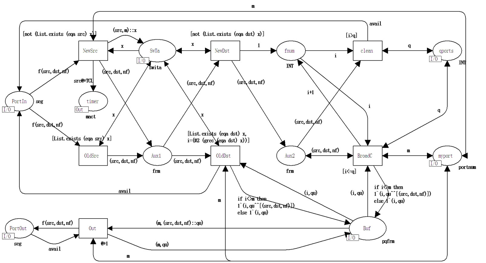
Figure 6. Model of 802.1D switch port (port).
for that the queue is extracted from place Buf with first frame separated via arc inscription (m,f::qu), then the queue without the first frame is returned via arc inscription (m,qu). Operation ^^ implements the queues concatenation; operation :: separates the header element.
5.2. PBB Interior Switch Port Model
Port model PBBport of PBB interior switch is represented in Figure 7. The work of PBB interior switch port is in many ways very similar to the work of a usual switch port shown in Figure 6 with the only difference that B-MAC addresses of 802.1ah frame are used instead of C-MAC addresses.
The type PBBseg is used for the description of PBB segment channel, which can be either free (constant bavail) or busy with transmission of frame b. The type PBBfrm is used for the description of frame b consisting of backbone sender address bsrc, backbone destination address bdst and encapsulated 802.3 frame frm. Switching table contains backbone addresses B-MAC only. The pqxfrm type of the buffer Buf describes queues of frames xfrm for ports; the type xfrm is represented by the union of frames cf of the type frm or frames bf of the type bfrm. PBB interior switch processes bfrm frames only; the possibility of a frame union is used in the models of edge switches.
The main differences in the work of the port are connected with the PBBfrm frame type processing instead of frm and bsrc, bdst addresses usage instead of src, dst addresses correspondingly. Moreover, transition NotMYbdst determines that frame is not addressed to the current switch while transition MYbdst models the processing of (subservient) frame addressed to the current switch via absorption of the frame and increment of counter dfn into place dfPBB.
5.3. PBB Edge Switches Ports Models
The basic difference of PBB edge switch ports consists in the processing both C-MAC addresses and B-MAC addresses and running switching tables, which provide the mapping of C-MAC addresses into B-MAC addresses. Moreover, the broadcasting of two kinds is implemented: on C-ports and on B-ports transmitting frames of different types.
For the description of queues elements of the internal buffer, the union data type xfrm is used, which can store either frame cf of the type frm or frame bf of the type PBBfrm. For flat relative representation of multilevel switching tables and addresses mapping, the data type PBBswi is used, which contains destination address dst, backbone destination address bdst and port number pnum. The field bdst duplication in several records has the advantage of the quick search of complete information by the key dst.
5.3.1. C-port
Model of C-port cport of PBB edge switch is represented in Figure 8. The basic difference from ports port, PBBport
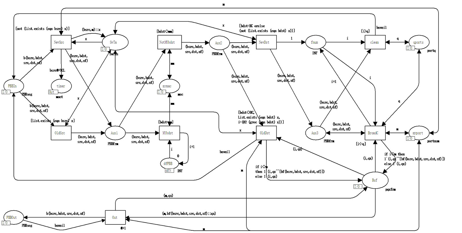
Figure 7. Model of PBB interior switch port (PBBport).
(Figures 6 and 7) consists in the refilling of switching table with records containing besides src backbone address bsrc, which coincides with own B-MAC address. Moreover, the function of recursive search grecB is modified as well as the function eqaB of addresses comparison for the records of the type PBBswi processing; the second (#2) and the third (#3) fields of the table PBBswT are employed; an additional checking known destination address on the belonging to own network is implemented via transitions OldDstMy, OldDstNotMy. If a known destination address dst belongs to own network (transition OldDstMy), then the record cf is formed, which is forwarded to C-port. If a known destination address dst does not belong to own network (transition OldDstNotMy), then the record bf is formed, which is forwarded to B-port, while not only the destination port number (#3(grecB(eqaBdst)y)) but also backbone destination address (#2(grecB (eqaBdst)y)) are determined from the table. The broadcasting (transition BroadC) distinguishes ports via place mPBBp, which stores the number of the first B-port; ports are enumerated sequentially: at first all the C-ports, then all the B-ports. That is why the condition I < pbp pointed in the inscription of the arc BroadC- > Buf, separates C-ports only and its alternative (then)—B-ports; depending on this, either cf or bf record is put into the buffer correspondingly. For the broadcasting into backbone a constant BC equaling to 255 is used as the backbone destination address bdst.
5.3.2. B-port
Model of PBB edge switch port bport represented in Figure 9 is the most complicated that is why it is considered closely. Passive listening (transitions NewSrc, OldSrc) fills in the table SwTa with records containing both customer src and backbone bdst addresses from the current frame. Then the backbone destination address bdst is analyzed; the alternatives are represented by the following transitions: bdstMy—own bdst of the current switch, bdstBC—broadcasting bdst, bdstNotMy—address bdst of some other PBB switch. Then the search in the table is implemented: the key is the destination address dst for own bdst (transitions dstNew, dstOld), the key is bdst address for foreign bdst (transitions bdstNew, bdstOld). In the both cases at the successful search completed, the frame is forwarded (transitions bdstOld, dstOld) into the buffer; in the first case (transition bdstOld)—without changes, in the second case (transition dstOld)—encapsulated 802.3 frame is extracted. The other conditions (transitions dstNew, bdst BC, bdstNew) lead to the start of broadcasting (transition BroadC). Thus, the set of five alternatives is formed: bdstMy& dstNew, bdstMy& dstOld, bdstBC, bdst-NotMy&bdstNew, bdstNotMy& bdstOld. Moreover, the case of possible error is processed separately (transition wrong): the frame is addressed to the current switch (bdstMy), address dst is contained in the table but the corresponding record of the table contains bdst which distinguishes from the address of the current switch.
For the correct forming of the broadcasting, additional Boolean indicators are used in the following places: BCcport—broadcasting on C-ports; BCbport— broadcasting on B-ports. Each of three alternatives of the broadcasting forms its own set of the indicators:
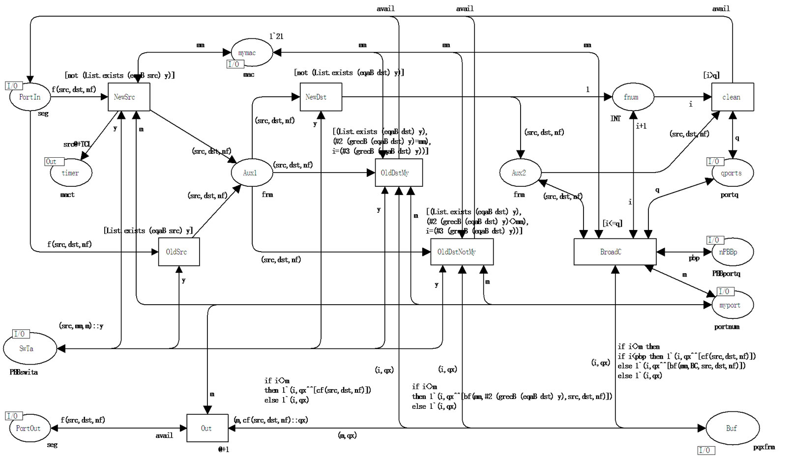
Figure 8. Model of PBB edge switch C-port (cport).
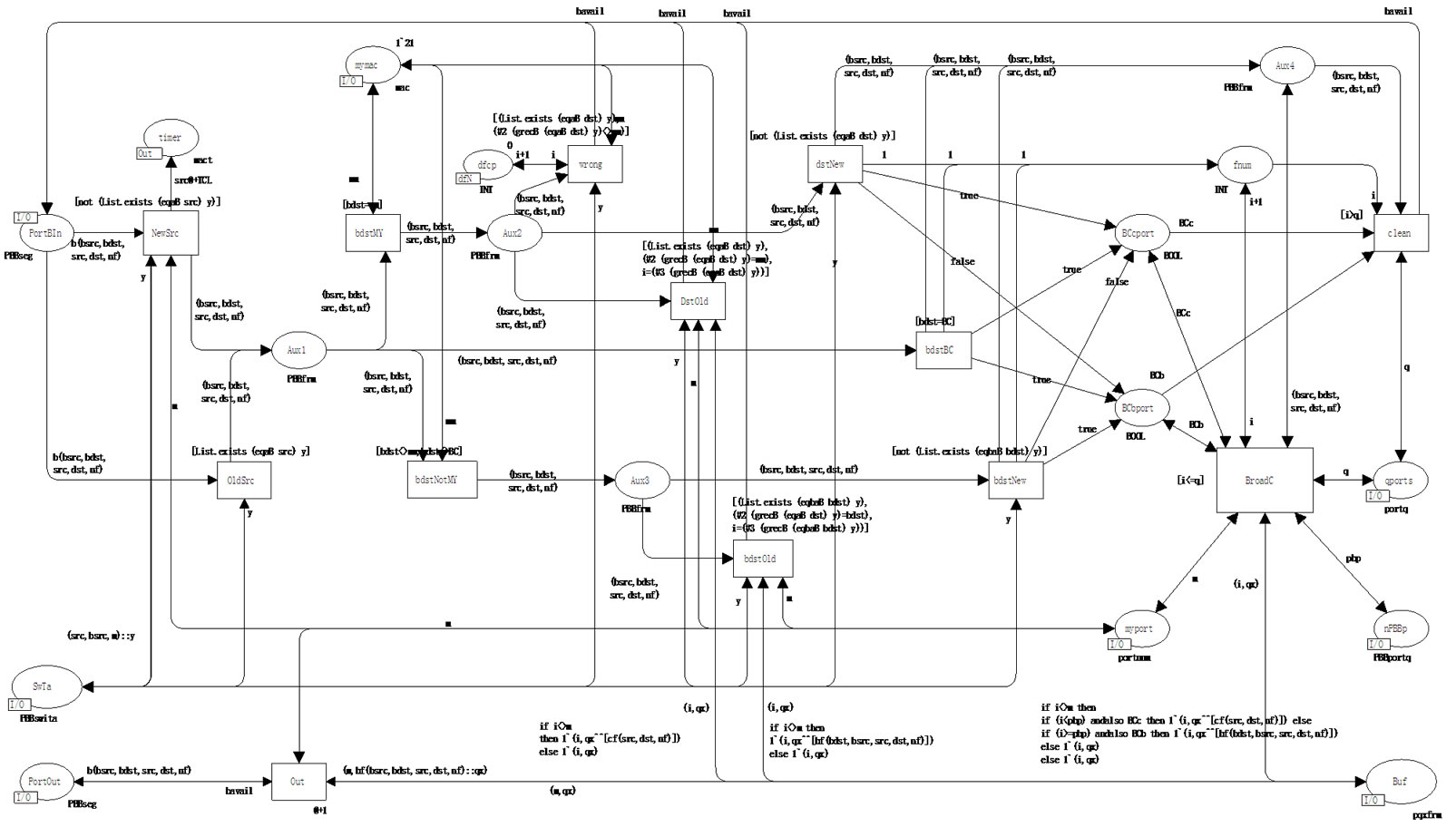
Figure 9. Model of PBB edge switch B-port (bport).
bsdtMy&dstNew—BCcport = true & BCbport = false, bdstBC—BCcport = true & BCbport = true, bdstNotMy &bdstNew–BCcport = false & BCbport = true. Depending on the combination of indicators the inscription of the arc BroadC- > Buf forms broadcasting frames forwarded to C-ports and B-ports.
Note that as the elements of the buffer queues are represented by the union, the output channels of C-ports (transition Out) extracts records cf from the buffer, Bport—records bf and transmit the corresponding frames into the corresponding segments (either of the type seg or PBBseg).
6. Terminal Equipment Models
In the present work, the models of the terminal equipment represented in [9,10] are used. Workstation WS generates queries to servers periodically; the distribution of time between queries is given by the random function Delay(). Server S executes the query of workstation and returns a random number of the reply frames; the distribution of frames number is given by the random function Nsend(); the distribution of query processing time is given by the random function Dexec(). Results of various laws of random values distribution were analyzed: uniform, Poisson, Erlang.
Into the models of the terminal equipment, counters were added represented by the following fused places: SndFrmT of the kind sfT—the counter of sent frames, RcvFrmT of the kind rfT—the counter of received frames, DrpFrmT of the kind dfT—the counter of dropped frames. For the convenience of the model characteristics evaluation, the counters are shifted to the main page (Network). Moreover, measuring workstations MWS implement the evaluation of the network response time directly during the simulation process [9,10].
7. Simulation Results Analysis
Primarily, the separate components debugging was implemented, then the complex debugging of the network model; the tracing of separate frames delivery processes and the filling up of address tables was implemented. Using additional counters it was ascertained that all the sent frames are delivered to their destinations. Dynamically filled up address tables completely correspond to the structural scheme of the network.
The model time unit (MTU) is equal to 1.2 ms, it corresponds to the frame transmission time into 10 Gbps segment. The time of equipment components work was not modeled since it requires nanosecond time scale which complicates the evaluation of the network functioning on prolonged time intervals.
The model measuring fragments are represented by the measuring workstations MWS for the evaluation of the network response time and the frames counters for the evaluation of the performance and the effective performance. The source of overhead in Ethernet technology including PBB is the broadcasting usage as well as the resources spending on the spanning trees construction. The present model allows the estimation of the performance portion spent on the broadcasting only; the evaluation of the spanning tree algorithms work was not implemented.
The counter DrpFrmT of the kind dfT in the main page of the model contains the total number of the broadcasting frames delivered to the terminal equipment; the counter RcvFrmT of the kind rfT—the total number of the delivered useful frames. At the stopping of the model under expired time condition, the content of RcvFrmT is lesser than SndFrmT—the counter of sent frames, which is caused by definite number of frames are in the process of their delivery into the network; but at the generating given number of frames and the model stopping under the absence of events condition, the values of the both counters are equal.
The effective performance of network depends considerably on the records ageing time TCL of the address tables. Moreover, at the network switching on (new subnets connection), a short-term overload is produced because of intensive broadcasting, which leads to temporary decrease of QoS (the network response time). The dynamics of the broadcasting and the response time (as a quality of service characteristic) are shown in Figure 10. In the graphs, a splash of broadcasting at the network switching on and its influence on the response time are shown as well as the second wave of the broadcasting after the cleaning of the address tables (after 12 s.), which influence is smoothed on time.
The dependencies of the effective performance and the response time on the records ageing time are shown in Figure 11. The increase of the records ageing time leads to the improvement of the network performance as well as QoS but it decreases the capabilities of the adaptation to changes of structure and leads to incorrect frames delivery as the result of irrelevant address table records usage.
The influence of the records ageing time is getting stronger at the traffic intensity increase according to evaluations represented in Figure 12. The effective performance of the network is increased at traffic intensity increase (though it leads to the QoS deterioration), which is caused by the increase of frequency of address tables records usage.
Thus, in spite of the considerable advantage, PBB technology possesses the definite imperfections, which complicate the guaranteeing of given QoS and require the performance reservation for the possible overloads smoothing. Note that in the present work the virtual networks, which allow the broadcasting traffic isolation (within the bounds of a virtual network), were not considered.
The preliminary comparative analysis of two technologies is carried out on the base of the models constructed in the present work and the models of E6 networks [6]. The absence of service broadcasting in E6 allows the guaranteed QoS. Hierarchical structure of E6

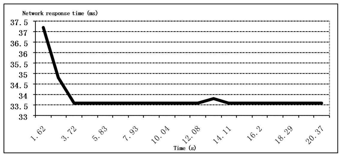
Figure 10. Dynamics of broadcasting and QoS after the switching on.
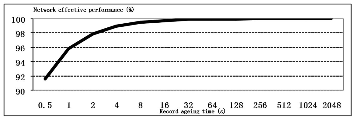
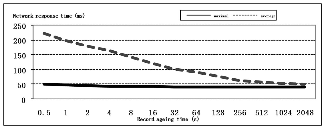
Figure 11. The influence of the record ageing time on the performance and QoS
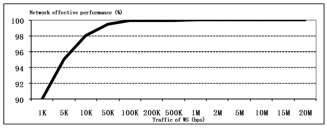
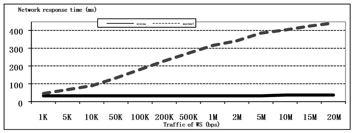
Figure 12. The influence of the traffic intensity on the performance and QoS.
network (including the backbone) is given by the hierarchical E6 addresses and does not lead to the lengthening of the frame header; in PBB each new level of backbone hierarchy requires not less than 12 additional bytes of the frame header (for the pair of B-MAC addresses). Moreover, stack E6 annuls 20-36 bytes of protocols TCP, IP headers for each encapsulated packet. At the encapsulation IP-Ethernet, PBB technology stipulates the duplicate mapping of addresses: IP- > C-MAC, C-MAC- > BMAC, while E6 completely annuls the address mapping within network due to uniform E6 address usage.
8. Conclusions
In the present work the basic components of PBB network models were constructed: PBB interior switch, PBB edge switch—with dynamic filling up of address tables. The modeling of PBB network functioning was implemented. The analysis of simulation results allows the conclusion regarding definite imperfections of PBB technology caused by the broadcasting and sensitivity to the ageing time of the address tables’ records, which complicates the guaranteeing of a given QoS.
The preliminary comparison confirms definite advantages of E6 addressing before PBB. For a thorough comparative evaluation of the two technologies, it is necessary the construction of models displaying the peculiarities of IP-Ethernet encapsulation, the filling up E6 dynamic address tables, the functioning of PBB virtual networks, which are the directions for future research.
9. References
[1] L. Fang, R. Zhang and M. Taylor, “The Evolution of Carrier Ethernet Services—Requirements and Deployment Case Studies,” IEEE Communications Magazine, Vol. 46, No. 3, March 2008, pp. 69-76.
[2] “IEEE Standard for Local and Metropolitan Area Networks—Virtual Bridged Local Area Networks, Amendment 7: Provider Backbone Bridges,” IEEE Std 802.1ah™-2008, 12 June 2008, pp. 1-109.
[3] F. Balus, M. Bocci and M. Aissaoui “VPLS Extensions for Provider Backbone Bridging,” Work in Progress, IETF, July 2008, pp. 1-25
[4] P. P. Vorobiyenko, D. A. Zaitsev and O. L. Nechiporuk, “World-Wide Network Ethernet?” Zviazok (Communications), No. 5, 2007, pp. 14-19.
[5] P. P. Vorobiyenko, D. A. Zaitsev and K. D. Guliaiev, “Way of Data Transmission within Network with Substitution of Network and Transport Layers by Universal Technology of Data-Link Layer,” Patent of Ukraine on Utility Model, No. 35773, 2008.
[6] K. D. Guliaiev, D. A. Zaitsev, D. A. Litvin and E. V. Radchenko, “Simulating E6 Protocol Networks Using CPN Tools”, Proceedings of International Conference on IT Promotion in Asia, Tashkent, 22-26 August 2008, pp. 203-208.
[7] M. Beaudouin-Lafon, W. E. Mackay, M. Jensen, et al., “CPN Tools: A Tool for Editing and Simulating Coloured Petri Nets,” International Conference of Tools and Algorithms for the Construction and Analysis of Systems, Genova, 2-6 April 2001, pp. 574-580. http://www.daimi. au.dk/CPNTools
[8] K. Jensen, “Colored Petri Nets: Basic Concepts, Analysis Methods and Practical Use,” Springer-Verlag, Berlin, 1997.
[9] D. A. Zaitsev and T. R. Shmeleva, “Switched Ethernet Response Time Evaluation via Colored Petri Net Model,” Proceedings of International Middle Eastern Multiconference on Simulation and Modelling, Alexandria, 28-30 August 2006, pp. 68-77.
[10] D. A. Zaitsev, “An Evaluation of Network Response Time Using a Coloured Petri Net Model of Switched LAN,” Proceedings of 5th Workshop and Tutorial on Practical Use of Coloured Petri Nets and the CPN Tools, Aarhus, 8-11 October 2004, pp. 157-167.
[11] D. A. Zaitsev and A. L. Sakun, “An Evaluation of MPLS Efficacy Using Colored Petri Net Models,” Proceedings of International Middle Eastern Multiconference on Simulation and Modelling, Amman, 26-28 August 2008, pp. 31-36.
[12] M. V. Bereznyuk, K. K. Gupta and D. A. Zaitsev, “Effectiveness of Bluetooth Address Space Usage,” Proceedings of 20th International Conference, Software & Systems Engineering and their Applications, Paris, 4-6 December 2007.