Advances in Chemical Engineering and Science
Vol.3 No.2(2013), Article ID:30503,7 pages DOI:10.4236/aces.2013.32018
Copper Recovery from Barren Cyanide Solution by Using Electrocoagulation Iron Process
1Institute Technology of Saltillo, Saltillo, Mexico
2Departament of Chemistry and Metallurgy, University of Sonora, Hermosillo, Mexico
3Faculty of Metallurgy, University of Coahuila, Monclova Coah, México
Email: *jrparga@its.mx
Copyright © 2013 José R. Parga et al. This is an open access article distributed under the Creative Commons Attribution License, which permits unrestricted use, distribution, and reproduction in any medium, provided the original work is properly cited.
Received December 14, 2012; revised January 30, 2013; accepted February 20, 2013
Keywords: Copper Recovery; Electrocoagulation Process; Bipolar Iron Electrodes; Cyanide
ABSTRACT
This paper is a brief overview of the role of inducing the nucleated electro winning of copper by using iron electrodes in electrocoagulation (EC) process. Cyanide compounds are widely used in gold ore processing plants in order to facilitate the extraction and subsequent concentration of the precious metal. Owing to cyanide solution employed in gold processing, effluents generated have high contents of free cyanide as well as copper cyanide complexes, which lend them a high degree of toxicity. In this regard, two options for the treatment of cyanide barren solutions has been used; in two ways; first for cyanide destruction by oxidation with the use of the EC process, in theory, has the advantage of decomposing cyanide at the anode and collecting copper simultaneously by a sludge of copper magnetic iron. In both cases excellent performance can be achieved using the high capacity of the bipolar iron EC technology. We found that it is possible to reduce the copper cyanide complex from 720 mg·l−1 to below 10 mg·l−1 within 20 minutes.
1. Introduction
Due to the dwindling resources of simple cyanide extractable gold deposits, a large proportion of the gold processed in the 21st century will be recovered from complex gold ores, many of which will contain soluble copper minerals. It has been estimated that about 20% of all gold deposits have significant copper mineralization commonly associated with chalcopyrite, tetrahedrite, tennantite, enargite as well as bornite and chalcocite in certain ores [1]. It has also been found that the majority of copper minerals including copper oxides, carbonates, sulfides (with the exception of chalcopyrite) and native copper are highly soluble in cyanide solutions [2]. These copper containing minerals are problematic because, when ores containing such minerals are leached with cyanide to recover the gold, copper also dissolves to form stable copper cyanide complexes. The dissolution of copper consumes a substantial quantity of cyanide and thus, if not recovered imposes a significant financial cost on the gold mine. The presence of copper also causes other problems such as competition with gold to adsorb on carbon unless a sufficient free cyanide concentration is maintained, depletion of gold electrowinning cell efficiency, and gold losses by cementation onto certain copper minerals. Ores containing greater than 0.5% reactive copper may be generally considered uneconomical to process via conventional cyanidation due to the high reagent cost. Therefore, it is necessary to reduce the amount of copper, especially in leaching circuits, in order to increases the dissolution of gold and silver, to achieve this goal it is possible to remove the copper from barren solution after Merril-Crowe process using the electrocoagulation process (EC). This process can be interesting for the copper cyanide removal from processed solutions after the Merrill Crowe process, also has low cost of operation and investment.
2. Copper Cyanide Chemistry
The major challenges to the processing of gold-copper ores using cyanidation is that of the high cyanide consumptions that are typically experienced, along with effective control of the leach, particularly when there is variable cyanide-soluble copper in the ore. It is widely accepted that gold dissolution in cyanide solutions occurs as sequence of two reactions shown in Equations (1) and (2), Elsner’s equation shows that oxygen is critical for the dissolution of gold.
 (1)
(1)
 (2)
(2)
The stoichiometry of the process shows that 4 moles of cyanide are needed for each mole of oxygen present in solution. At room temperature and standard atmospheric pressure, approximately 8.2 mg of oxygen are present in one liter of water. This corresponds to 0.27 × 10⁻³ mol/L accordingly, the sodium cyanide concentration (molecular weight of NaCN = 49) should be equal to 4 × 0.27 × 10−3 × 49 = 0.05 g/L or approximately 0.01%. This was confirmed in practice at room temperature by a very dilute solution of NaCN of 0.01% - 0.5% for ores, and for concentrates rich in gold and silver of 0.5% - 5% [3]. Also, lime is added to keep the system at an alkaline pH of 10.5 - 11.0. Other factors affecting gold leaching kinetics are grain size, agitation speed, temperature, pressure, foreign ions and cyanicides.
Free cyanide exists as the uncomplexed cyanide ion, CN−, and molecular hydrogen cyanide, HCN. These species are related by the acid dissociation of HCN:
![]() (3)
(3)
The concentration of free cyanide is the sum of the CN− and HCN concentrations, and the equilibrium diagram shown in Figure 1 illustrates the distribution.
This figure shows the proportions of free cyanide as CN−, and HCN as a function of pH at 25˚C. At pH values below 7, cyanide is predominantly present as the unionized HCN molecule, which is easily volatilized because of its high vapor pressure. The equilibrium is displaced in favor of cyanide ion formation at pH values above 7.
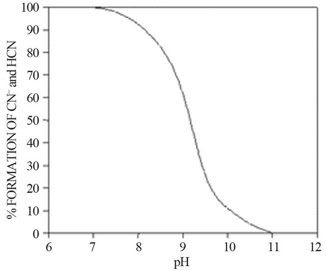
Figure 1. Equilibrium distribution diagram for cyanide as a function of pH.
Hydrogen cyanide (HCN), also known as hydrocyanic acid, is a colorless gas or liquid with a boiling point of 25.7˚C, a vapor pressure of 100 kPa at 26˚C and Henry’s Law constant of 6.4 atm/mole [4], this makes HCN very volatile. Thus, low pH, high temperature, low pressure, and intimate contact with air, all tend to increase the rate of dissipation of cyanide from solution as hydrogen cyanide. In addition to free cyanide, other complexes such as the metal cyanide complexes formed with gold, silver, copper, nickel, iron and cobalt must be considered.
In cyanidation plants all around the world, the concentration of cyanide used to dissolve gold in ores is typically higher than the stoichiometric ratio, due to the solubility of other minerals. Free cyanide produces complexes with several metallic species, especially transition metals, which show a broad variation in both stability and solubility. Many common copper minerals are soluble in the dilute cyanide solution under typical of leach conditions found in the gold cyanidation process. Minerals such as azurite and malacite, are rapidly leached and are soluble in dilute cyanide solutions.
Enargite and chalcopyrite leach more slowly but are sufficiently soluble to cause excessive cyanide loss and contamination of the pregnant leach solutions. In reactions in aqueous solutions the cupric ion is rapidly converted to cuprous form and then copper forms a series of extremely stable soluble complexes in cyanide such as:
 (4)
(4)
 (5)
(5)
 (6)
(6)
 (7)
(7)
Under typical gold cyanidation conditions  has been shown to be the dominant species from the EhpH diagram for the copper-cyanide-water system [4,5]. The high consumption of cyanide during the cyanidation of copper-gold ores is due to the fact that copper forms complexes of high coordination numbers with cyanide (Reaction 3 to 6),
  in particular. Therefore, hydrometallurgical treatment of these ores by cyaniding as a rule gives rise to a series of difficulties associated with increase in the cyanide consumption and decrease in the dissolution rate of gold and silver, and in the cementation process. This precipitate is of low quality, because the copper is precipitated along with gold and silver, resulting in a higher consumption of zinc dust, fluxes in the smelting of the precipitate and shorter life for crucibles.
In this regard a study is proposed to remove copper cyanide ions with, a very promising electrochemical treatment technique, which does not require chemical additions. This process is electrocoagulation (EC). The EC process operates on the principle that coagulation of copper cyanide ions from barren solutions from the MerrillCrowe process is caused by the combined effects of electrolysis gases (H2 and O2) and the electrolytic production of cations from the iron anodes that corrode during electrolysis.
3. Electrocoagulation Fundamentals
The EC process operates on the principle that the cations produced electrolytically from iron and/or aluminum anodes enhance the coagulation of contaminants from an aqueous medium. Electrophoretic motion tends to concentrate negatively charged particles in the region of the anode and positively charged ions in the region of the cathode. The consumable, or sacrificial, metal anodes are used to continuously produce polyvalent metal cations in the vicinity of the anode. These cations neutralize the negative charge of the particles carried toward the anodes by electrophoretic motion, thereby facilitating coagulation. In the flowing EC techniques, the production of polyvalent cations from the oxidation of the sacrificial anodes (Fe and Al) and the electrolysis gases (H2 and O2) works in combination to flocculate the coagulant materials [6], the gas bubbles produced by the electrolysis carry the pollutant to the top of the solution where it is concentrated, collected and removed. Figure 2 illustrates the schematic diagram of the process.
Generally, in the EC process bipolar electrodes are used. Pretorius [7] and Mameri [8] have reported on the use of cells with bipolar electrode arranged in series. These cells, operated at relatively low current densities, produce iron or aluminum coagulant in a more effective, fast and economical manner when compared to chemical coagulation. The savings result from a reduction in the time necessary for the treatment and an increase in the anodic area improved the efficiency of the electrolysis [7,8]. An electrocoagulation cell with bipolar electrodes
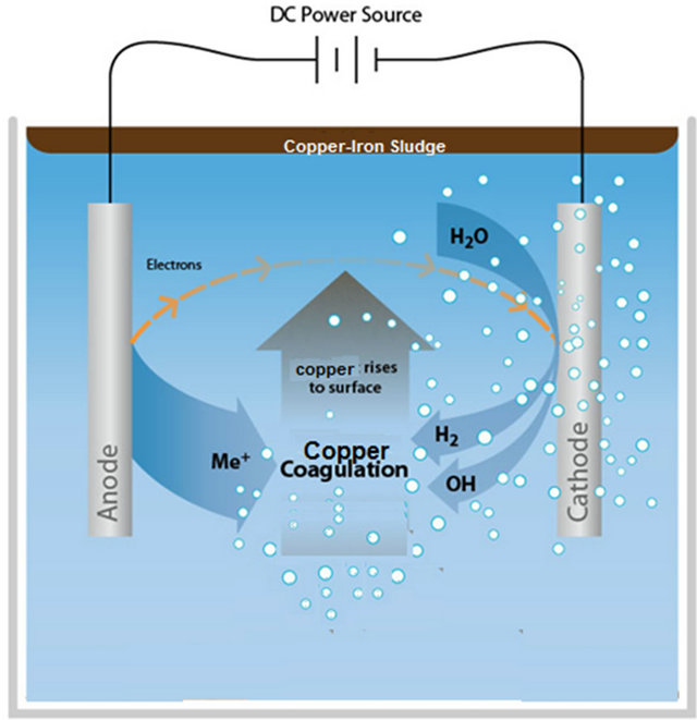
Figure 2. Schematic diagram of the EC process.
connected in series is shown in Figure 3. The inner electrodes are bipolar, that is they carry both positive and negative charges on opposing faces. These charges develop on the electrode surfaces and are opposite in sign of the charge carried by the parallel electrode surface (refer to Figure 3). During electrolysis the positive side of these bipolar electrodes undergoes anodic reactions, while on the negative side, cathodic reactions occur.
The released ions neutralize the charge of the particles and thereby initiate coagulation. The bipolar arrangement reduces the time needed for the treatment due to the increase in surface area mentioned above. This arrangement also has the practical advantage of simplified set-up in that only two monopolar electrodes are connected to the electric power source with no interconnections between the inner bipolar electrodes.
The Chemical Reactions of the Electrocoagulation Process
The chemicals reactions that have been proposed to describe the mechanism of EC for the production of H2(g) and ![]() (cathode) and
(cathode) and ![]() (anode) [9] are:
(anode) [9] are:
 (8)
(8)
 (9)
(9)
![]() (10)
(10)
 (11)
(11)
 (12)
(12)
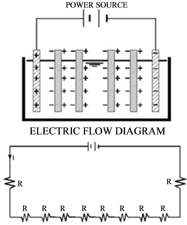
Figure 3. A schematic representation of a bipolar electrocoagulation cell and the equivalent electrical circuit (resistors reflects electrode surfaces).
 (13)
(13)
Overall reaction.
(14)
The pH of the medium usually rises as a result of this electrochemical process and the Green Rust formed
 remains in the aqueous stream as a gelatinous suspension, which can remove the gold and silver from pregnant cyanide rich solutions, either by complexation or by electrostatic attraction followed by coagulation and flotation.
Formation of rust (dehydrated hydroxides) occurs a while after the process, as shown in the following:
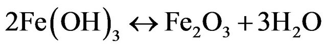 (hematite) (15)
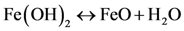 (16)
(16)
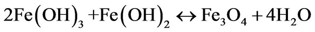 (magnetite) (17)
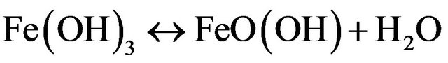 (goethite, lepidocrocite) (18)
A schematic representation of these reactions in an EC process, using iron electrodes, is shown in Figure 4. As mentioned above, the gas bubbles produced by electrolysis carry the copper along with the sludge to the top of the solution where it is collected and removed [10]. However, it is the reactions of the metal ions that enhance the formation of the coagulant. The metal cations are hydrolyzed, releasing hydrogen ions that result in hydrogen evolution at the cathode, to yield both soluble and insoluble hydroxides that will react with or adsorb copper from the cyanide solution and also contribute to coagulation by neutralizing the negatively charged colloidal particles that may be present at neutral or alkaline pH.
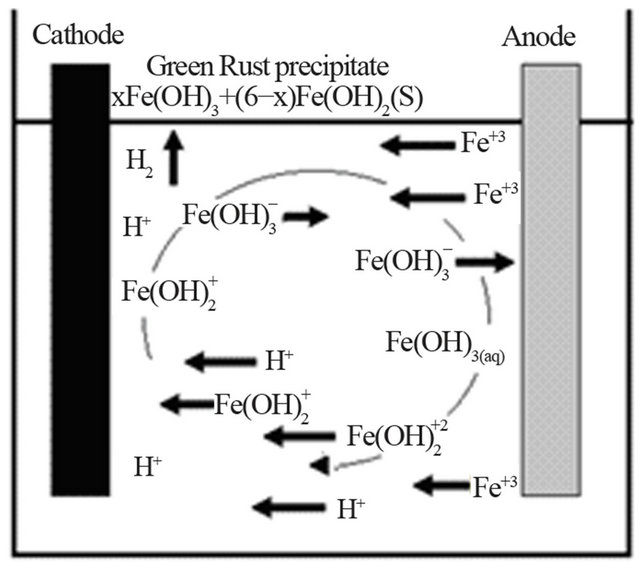
Figure 4. An illustration of the EC mechanism (arrow indicate the migration of ions, the H2 evolution and the formation of green rust).
This enables the particles to approach closely and agglomerate under the influence of Van der Waals attracttive forces. The pH of the medium rises as a result of this electrochemical process and the Fe(OH)n(s) formed remains in the aqueous stream as gelatinous suspension, which can remove the  from the barren solution, either by complexation or by electrostatic attraction followed of coagulation and flotation [11]. Generally, in the EC process, bipolar electrodes are used. It has been reported that cells with bipolar electrodes, connected in series and operating at relatively low current densities [12], produce iron or aluminum coagulant more effecttively, more rapidly and more economically when compared to chemical coagulation.
4. Experimental Details
The experimental work was performed using a barren solution from the Merrill Crowe process containing an average in the range of 660 - 712 ppm of copper. EC experiments were performed using a 600 ml Pyrex beaker glass (Figure 5), equipped with two iron electrodes (10 cm × 2.5 cm) with an electrode separation of 5 mm. A regulated power supply (model Steren PRL-25) to provide the necessary energy to the electrocoagulation cell, magnetic stirrer (Model PC-310, Corning) with 100 rpm was used, and the initial and final pH was taken with a pH meter (VWR Scientific 8005), filtration was performed with Whatman filter paper No.42. To determine the adsorption copper in iron hydroxide species generated at the anode, a barren solution after the cementation process was used that was provided by the William Mine Co. This solution contained an average of 0.02 mg/L gold and 0.1 mg/L silver along with amounts of zinc, lead. Among others, the analysis was performed according to EPA 200.7 (EPA 200.7 is an analytical method for
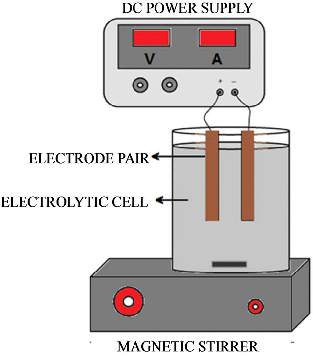
Figure 5. EC schematic diagram of the experimental setup.
detection of metals and trace elements by ICP/atomic emission spectrometry). The solution and the solids were separated by filtration through filter paper, the sludge from the EC was dried for 8 hrs in an oven at 80˚C. The tables below show the initial conditions of the EC test to remove copper.
Optimization of Parameters
In order to find the optimum parameters of the EC process for the removal of copper, experiments were carried out by changing the pH of the solution, residence time in the EC cell and voltage and amperage.
5. Results
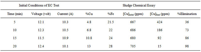
Tables 1-3 show the results for tests performed with 4 grams/liter of sodium chloride.
From these results it was determined that the optimum parameters were: pH 8, residence time of 20 minutes and 4 grams/liter of NaCl, this achieved 99% copper removal. Also, when the time increased from 15 to 20 minutes the removal of copper increased from 92% to 99%, this occurs in the pH range from 8 to 9 approximately, this coincides with the production of the magnetic iron, Fe3O4, which has magnetic properties that accelerates the process of adsorption of metals, the adsorption rate is then physically, because it is caused by the magnetic forces of the magnetite into copper, without altering their chemical composition. This removal of copper also can explain with a decrease in the zeta potential on iron hydroxides which causes a decrease in repulsive forces between the particles, generated collision between particles thus favors the formation of flocs which float to the water surface through micro bubbles generated from oxygen and hyTable 1. Results obtained for pH 8 and 4 g/liter of NaCl.
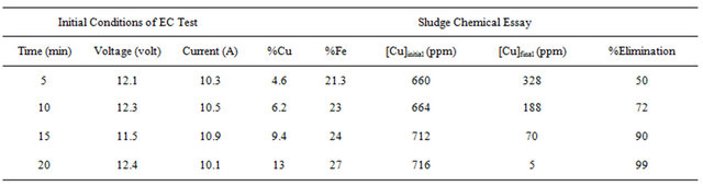
Table 2. Results obtained for pH 9 and 4 g/liter of NaCl.
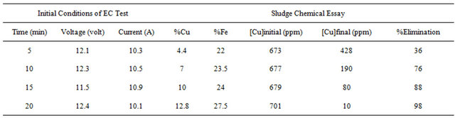
Table 3. Results obtained for pH 10 and 4 g/liter of NaCl.
drogen from the iron electrodes. Also, the advantages of the EC process is the decomposing of cyanide at the anode, where the anodic oxidation of cyanide is proportional to the alkalinity of the electrolyte and consistent with the following mechanism:
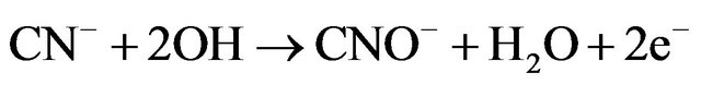 (18)
(18)
 (19)
(19)
 (20)
(20)
Figure 6 shows the graph of timeelimination where it is observed the behavior of the removal of copper.
6. Product Characterization
In order to identify the iron species present, Scanning Electron Microscope (SEM/EDX) was used to characterize the solid products formed during the EC process for removal of copper with iron electrodes.
6.1. Scanning Electron Microscopy (SEM/EDAX)
Figure 7 shows SEM image and Figure 8 shows EDAX of copper adsorbed on iron species. These SEM and EDAX results show that the surfaces of these iron oxide/
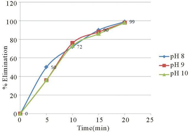
Figure 6. % Elimination of copper at pH 8, 9 and 10.
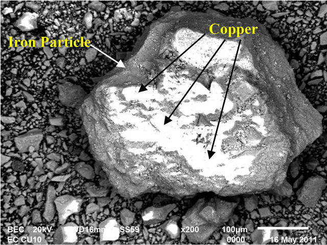
Figure 7. SEM image.
oxyhydroxide particles were coated with a layer of copper.
6.2. X-Ray Diffraction
Diffractograms were obtained with a Bruker AXS D4 Endeavor diffractometer operating with a Cu-K radiation source filtered with a graphite monochromator (λ = 1.5406 Å). The samples were wet ground to a fine powder (isopropyl alcohol from Sigma-Aldrich) and pressed into a sample holder. The XRD scans were recorded from 20˚ to 80˚ 2θ, with 0.02˚ step-width and with a 10 s counting time for every step-width (increment). Experiments were run at 40 kV and 40 mA power. Figure 9, shows a diffractogram of the filtered solid products (the feed solution contained 700 ppm of copper and the pH of the solution after EC was ~10).
This figure indicates the presence of magnetite, geothite, iron hydroxide oxide, and lepidocrocite in the solid products.
7. Conclusions
Electrocoagulation process was carried out to obtain a 99% of copper removal. The optimal operations conditions were: pH = 8, residence time: 20 minutes and 4 g/l of sodium chloride as conductivity modifier. The solid product obtained from EC process was 13% copper and 24% iron. The EC process does not generate any smell in the process of elimination of copper from the barren solution. During the EC process is not necessary to add any reagent (except Nacl), since the coagulating agent is generated in situ.
We found that it is possible to reduce the copper cyanide complex from 720 mg·l−1 to below 10 mg·l−1 within 20 minutes.
Also, the results of this study suggest that EC produces magnetic particles of magnetite. lepidocrocita and amorphous iron oxyhydroxide species that can be used to removal copper. The Scanning Electronic Microscopy, techniques demonstrate that the formed species are of magnetic type, like lepidocrocite and magnetite which adsorbed the copper particles on his surface due to the electrostatic attraction between both metals.
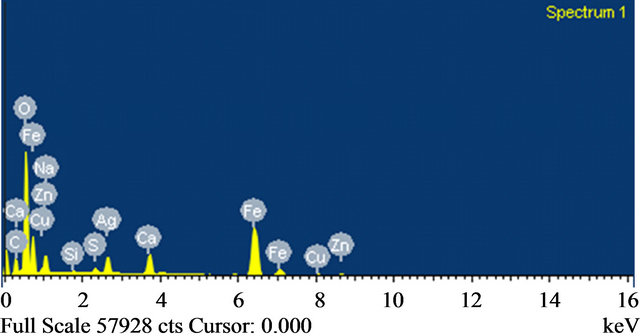
Figure 8. EDAX Analysis.
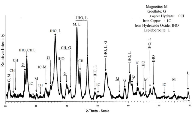
Figure 9. X-ray diffraction spectrum obtained from the EC product at pH = 10.
8. Acknowledgements
The authors wish to acknowledge support of this project to the National Council of Science and Technology (CONACYT) and to Dirección General de Educación Superior Tecnológica (DGEST).
REFERENCES
- D. M. Muir, S. R. LaBrooy and C. Cao, “Recovery of Gold Fromcopper-Bearing Ores,” In: R. J. Harden, Ed., Gold Forum Ontechnology and Practic, World Gold, 1989.
- J. O. Marsden abd C. I. House, “The Chemistry of Gold Extraction,” 2nd Edition, Society for Mining, Metallurgy and Exploration, Inc., Littleton, 2006.
- J. R. Parga, S. S. Shukla and D. L. Cocke, “Photocatalytic Detoxification of Cyanide and Recovery of Titanium Dioxide by Electrocoagulation,” Research Journal of Chemistry and Environment, Vol. 9, No. 1, 2005, pp. 60-63.
- S. T. Mudder, “The Chemistry and Treatment of Cyanidation Wastes,” Mining Journal Books Limited, London, 1991, pp. 277-278.
- M. D. Adams and R. Lawrance, “Biogenic Sulphide for Cyanide Recycle and Copper Recovery in Gold-Copper Ore Processing,” International Workshop on Process Hydrometallurgy, Hydroprocess Brisbone, 2008, pp. 14-16.
- O. Asare, K. Xue and T. Ciminelli, “Solution Chemistry of Cyanide Leaching Systems. In Precious Metals Mineralogy,” Extraction and Processing-Proceedings of and International Symposium, 1984, pp. 173-197.
- N. Mameri, A. R. Yeddou, H. Lounici, D. Belhocine, H. Grib and B. Bariou, “Defluoridation of Septentrional Sahara Water of North Africa by Electrocoagulation Process Using Bipolar Aluminum Electrodes,” Water Research, Vol. 32, No. 5, 1998, pp. 1604-1612. doi:10.1016/S0043-1354(97)00357-6
- W. A. Pretorius, W. G. Johannes and G. G. Lempert, “Electrolytic Iron Flocculant Production with a Bipolar Electrode in Series Arrangement,” Water South Africa, Vol. 17, No. 2, 1991, pp. 133-138.
- G. Pavas, M. P. Camargo, C. Jones and V. T. Pineda, “Oxidación Fotocatalítica de Cianuro,” Universidad EAFIT, Medellín, 2005, pp. 56-58.
- J. R. Parga, H. M. Casillas, V. Vazquez and J. L. Valenzuela, “Cyanide Detoxification of Mining Wastewaters with TiO2 Nanoparticles and Its Recovery by Electrocoagulation,” Chemical Engineering and Technology, Vol. 32, No. 12, 2009, pp. 1901-1908. doi:10.1002/ceat.200900177
- G. Vicuña and I. Tuñon, “Apuntes de Química Avanzada,” Departamento de Química-Física. Universidad de Valencia, 2006, pp. 103-115.
- A. G. Gupta and S. Kundu, “Adsorptive Removal of As(III) from Aqueous Solution Using Iron Oxide Coated Cement (IOCC): Evaluation of Kinetic Equilibrium and Thermodynamic Models,” Separation and Purification Technology, Vol. 51, No. 2, 2006, pp. 165-172. doi:10.1016/j.seppur.2006.01.007
NOTES
*Corresponding author.