Journal of Signal and Information Processing
Vol. 3 No. 2 (2012) , Article ID: 19557 , 6 pages DOI:10.4236/jsip.2012.32022
URAV Simulation Training System Based on Aerosim and Google Earth
![]()
1Optics and Electronic Department, Mechanical Engineering College, Shijiazhuang, China; 2College of Information and Communication Engineering, Harbin Engineering University, Harbin, China.
Email: *oec_ljw2009@sohu.com
Received January 7th, 2012; revised March 15th, 2012; accepted April 3rd, 2012
Keywords: Unmanned Reconnaissance Aerial Vehicle; Simulation Training; Google Earth; Visual Simulation
ABSTRACT
In order to solve the difficulties of traditional simulation training method on unmanned reconnaissance aerial vehicle, such as the low environment fidelity, difficulty of modeling and long cycle of development, a simulation training method based on Google Earth is put forward. The 6-DOF motion system of URAV is established through Matlab/Simulink. The visual simulation environment which is close to real scenes is formed though GE and software of SketchUp, and the visualization of flight data and elevation information of the region are also obtained through the software of GMS Aircraft Instrument and Measurement Studio. Experiments show that the method has satisfactory effects and its functions also can be strengthened, therefore it provides reference to related researchers.
1. Introduction
UAV has already become an important channel to obtain intelligence in regional conflicts with its advantage of zero casualties. It is mainly used for battlefield scout, intelligence collection, object tracking and fire shoot. However, live training takes a long time and it requires huge expenditure to train UAV operators. In order to reduce flight risks and damages brought by frequent use of equipment and decrease the cost of training [1,2], simulation training method is used to show the flight process of UAV directly. In addition, it enjoys merits of less cost, greater safety, repeatability and adaptability [3].
Simulation training system introduced in the paper is mainly used to train operators of UAV. The reality degree of simulation is very important to the simulation system. In the traditional simulation method, the view of operators in manned aerial vehicle (MAV) is adopted mainly, and flight scenes are simulated by virtual technology with the software of VRML, WTK, Creator/Vega Prime, OpenGL [3-5]. The flight scenes of the traditional simulation method are formed by texture mapping; therefore, it has low fidelity, the modeling process is also complicated and its development cycle is quite long. Because the terrain information is hypothetic so it is difficult to realize the consistency between flight process and real terrain environment. Now it is very hard for flight simulation system to achieve the consistency between flight characteristics and real flight conditions. Sometimes the difference of them is so great that it is very harmful to operators’ simulation training. The differences are tabulated in Table 1.
The 6-DOF (Degree of Freedom) motion system of URAV is established through Matlab/Simulink. It applies the information of Google digital global to establish a high fidelity dynamic aerial image scene in the paper which can intercommunicate with the data of UAV flight. Simulated scene is consistent with the attitude, velocity and position of UAV, thus the different visual effects can be realized such as moving, scaling and ranging.
2. System Structure
The basic principle of URAV simulation training method based on Aerosim and Google Earth is as shown in Figure 1. Operators send remote control orders by operating control panel, the orders are calculated by the Simulink model of URAV and the data of flight conditions is sent through serial interfaces. The data from serial interfaces are read though Visual C++ 6.0 so as to display the scene in real-time though GE and selects the GE elevation information under present conditions, in order to simulate terrain environment comprehensively and truly and imbed buildings, tanks and vehicles in the image, the software of SketchUp is adopted to make 3D modeling of the image. The model is added into flight scene through using KML language, the attitude flight path of URAV and

Table 1. The differences in development tools.
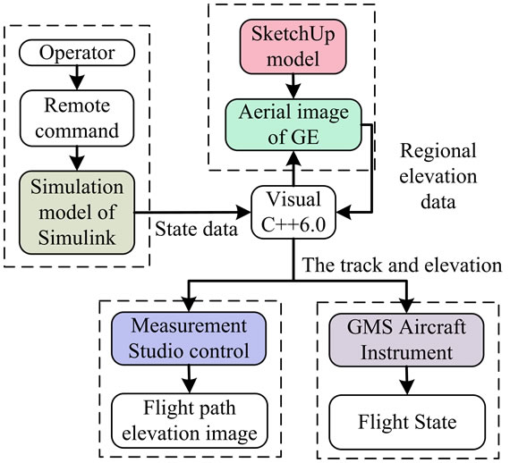
Figure 1. The structure of simulation training system.
its elevation information are shown in real-time with GMS Aircraft Instrument and 3D Graph control panel in the software of Measurement Studio.
3. Simulations
3.1. Simulation of the Flight Data
AeroSim toolbox in Simulink environment is the model tool to establish nonlinear 6-DOF dynamics model of airplane [6,7]. URAV model can be established on the basis of complete plane models through configuring corresponding plane parameter with the help of configuration files. The method can be used in different kind of UAV simulation trainings and it can reduce development time and difficulty of the training system.
The internal layout of the complete aircraft model is shown in Figure 2. All sub-systems were designed using the AeroSim blocks [8]. A simplified diagram is presented in Figure 3. The aerodynamics, propulsion, and inertia models compute the airframe loads (forces and moments) as functions of control inputs and environment (atmosphere and Earth) effects. The resulting accelerations are then integrated by the Equations of Motion to obtain the aircraft states (position, velocity, attitude, angular velocities). The aircraft states then will affect the output of the environment blocks at the next iteration (for example altitude changes result in atmospheric pressure changes, latitude and longitude variations result in gravity variations). Also, the aircraft states are used in the computation of sensor outputs (GPS, inertial measurements, etc.) [9]. In the model, the remote control order to drive plane model and outputs of flying posture angle and position information are based on S function as shown in Figure 4. The data of the system are transmitted through serial interface with using Serial Send toolbox in the software of Instrument Control. In order to make the simulation data more convenient for observing, the data of the system are shown in the picture and digital form.
3.2. Visualization of UAV Poster and Ground Information
3D coordinate is an ideal choice to show the UAV flight posture and terrain environment in flight region directly. 3D aerial image can reconstruct UAV motion in truth [10], which is helpful for evaluating operators’ training and improving training efficiency.
In the GCS software, the supervisory console for UAV’s state data is more intuitionistic and available by virtual instrument. GMS developed by USA can be used in Windows and transferred by software such as VC, so it decreases large works of sound code development. Airspeed, Altimeter, Artificial horizon, Compass are used in this paper which is as shown in Figure 5.
NI Measurement Studio is an integrated suite provided for Visual Studio 6.0 environment, includes various commonly used measurement and user interface controls, tools and class libraries, which greatly reduces developing time of various application programs. The 3D visualization of URAV’S posture image and ground information not only reflects the flight path of UAV, but also provides ground elevation information at the same time.
CWGraph3D Control can be edited if it is dragged into
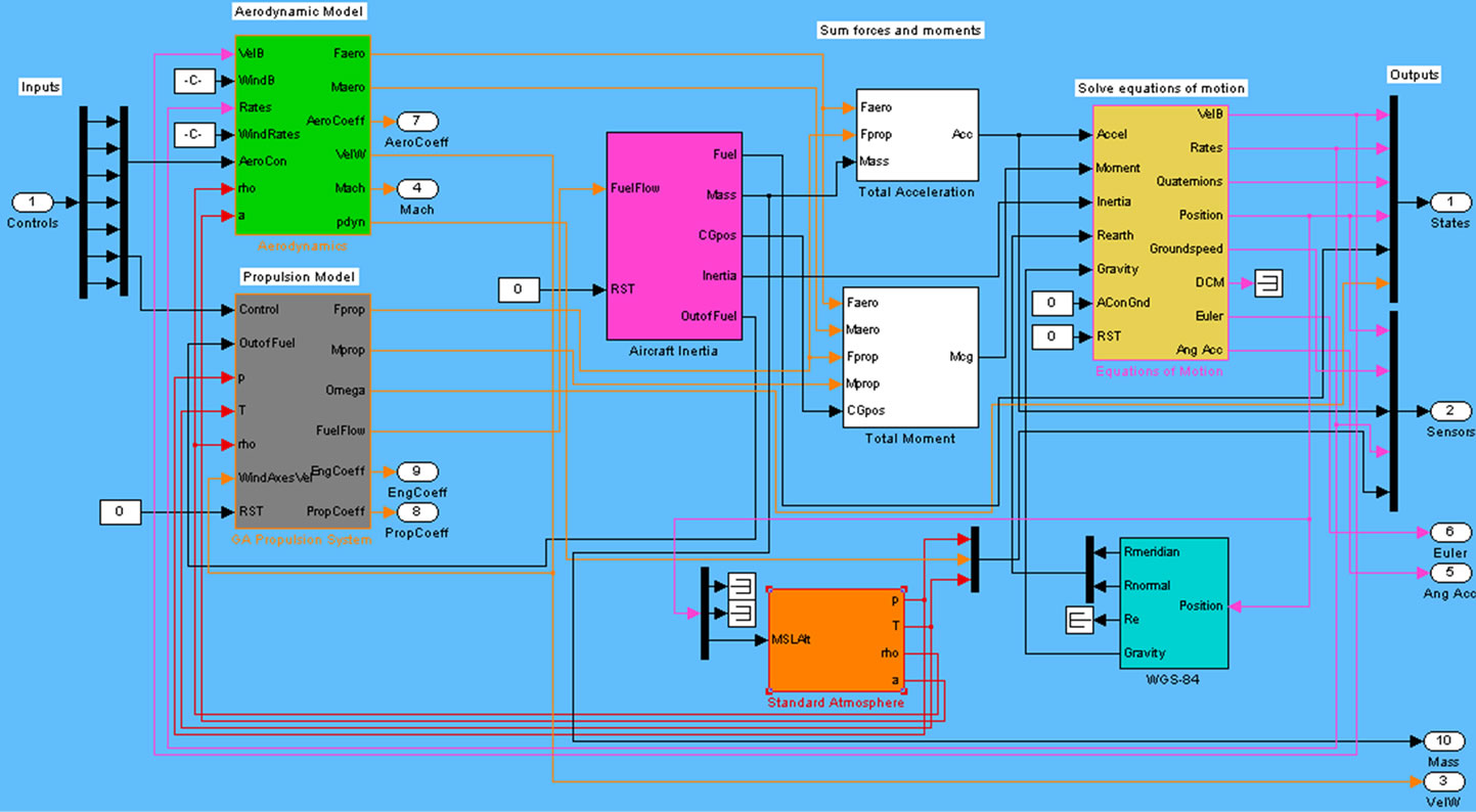
Figure 2. The URAV model through the software of AeroSim.
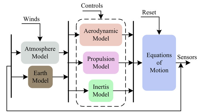
Figure 3. A simplified diagram of modules.
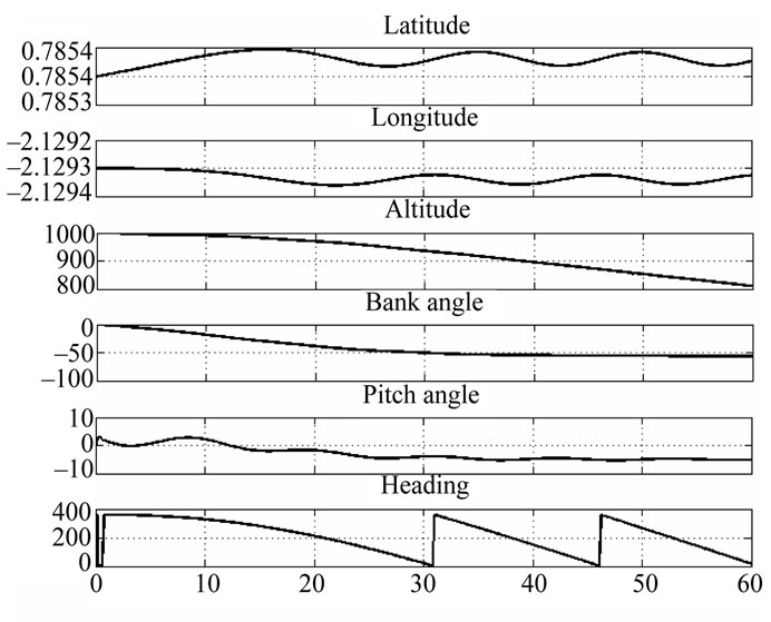
Figure 4. The flight condition data of UAV with 6-DOF.
dialogue box in the software. Caption() order can set the name of topic, includes coordinates of latitude, longitude and elevation. Flight path is drawn by Plot3Dcurve(). The function of Plot3DSimpleSurface() can be used to make simple surface plot, i.e. to draw a continuous curve of discrete flight path point. In terms of ground elevation information, it needs to obtain points on the screen by function GetPointOnTerrainFromScreenCoords() in GE COM API, and then elevation information is obtained by function GetAltitude(). At last, all the elevation information of image needs to be selected and rendered. The panel of SetStyle(CNiPlot3D::PlotStyles::Surface) can be used to cover the surface of vertex, which is as shown in Figure 6.
4. Simulation Environment
As known that the visual image data of GE is integration of satellite image and data of aerial photo. The highest resolution of GE can reach 0.5 m. It makes use of servers with great volume to integrate image data and other related information such as elevation information together; its volume can reach T-Bit level, which can provide a large quantity of data for the simulation training system.
From the analysis of the performance and characteristic of URAV, it can be known that the investigation task of URAV are mainly carried out through video cameras and the rotation of video camera can be realized in two degrees of freedom and focal length can be changed accordingly.
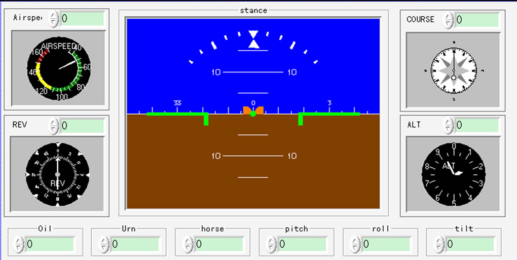
Figure 5. GMS aircraft instrument.
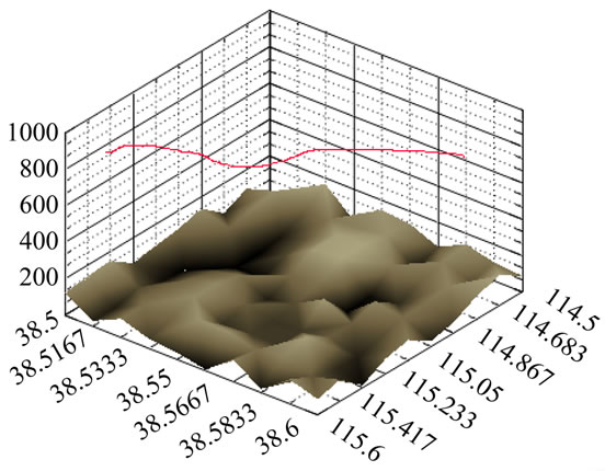
Figure 6. URAV flight path and ground elevation information.
Because of the similarity between GE image and camera-shot image of URAV, GE image is adopted in the paper as the scene of simulation training. Because the GE scene is the scene of the real world, it is realistic and the terrain matches the real terrain environment strictly compared with simulated environment. So operators can improve operation skills and will be more familiarized with environment at the same time through the training. The number of training scenes is not limited, so it enhances operators’ enthusiasm of training.
GE COM API provides great convenience to the redevelopment of GE [11,12]. Based on GE COM API, orders can be sent to control image translation and changes of 3D viewpoint through Visual C++6.0.
4.1. Control of Flight Environment
Accordingly to training requirement, the image should be displayed in full-screen and projector or large screen display. The related terrain environment should be used according to different training tasks; the method of the preserves data in the paper is though the high-speed cache by browsing GE. When training task is changed, the files of cache in different part should be used. The method is easy to be operated and controlled; therefore it has a wide application. The simulation data of UAV is transferred through the function of SetCameraParams() in the paper so as to realize the free control of flight environment. The grammar of the function is as follows:
BOOL SetCameraParams (double lat, double lon, double alt, AltitudeModeGE altMode, doublerange, double tilt, double azimuth, double speed).
Among them, lat, lon and alt represent latitude, longitude and elevation of UAV in flight process respectively. When focal length of the camera is changed, lat, lon, alt denote the actual position of simulation video camera after calculation, tilt is the motion angle of video camera in vertical direction, azimuth represents the motion angle in level direction. Speed represents the time of the image change to object position. The parameters are updated in real-time by the data received in serial interfaces so as to achieve the change of different scenes.
4.2. Generating Method of Task Object
Traditional scene simulation is based on rendering of flight environment, but it ignores complicated object model on the ground. However, the training task of URAV is to investigate terrain and important objects in certain region. GE provides 3D model map layer of regions around the globe, direct visual experience and feeling can be obtained in the training process. The 3D model is formed with the help of Google SketchUp and the virtual technology. As known that the GE provides a large number of architecture models, the modeling method of people and vehicles is proposed in the paper.
Compared with other 3D softwares, SketchUp is easy to use and be grasped. It can be conveniently communicated with other widely used design software, such as AutoCAD, 3Ds max, Revit. There already has a large quantity of models on the internet, in order to improve efficiency, we modifies existing models’ appearance and surface texture so as to make it match terrain environment appropriately. An example can be given to show how a vehicle model be set up through the method. First, the model is put into SketchUp and its appearance and surface texture are moderately adjusted, which is as shown in Figure 7. Then the position of GE is obtained and the model’s posture is also adjusted. The model is loaded to GE ground environment by KML language [13-15], as shown in Figure 8.
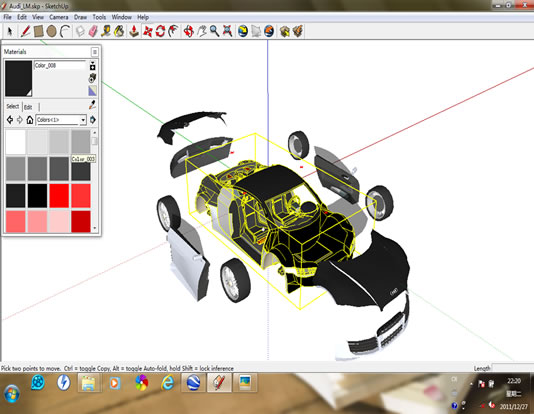
Figure 7. SketchUp modeling.
 (a)
(a)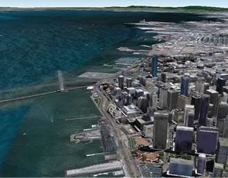 (b)
(b)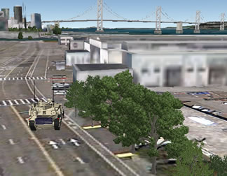 (c)
(c)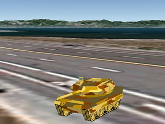 (d)
(d) (e)
(e)
Figure 8. Object task model imbedded in GE. (a) The car; (b) The bindings; (c) The trees; (d) The tank; (e) The helicopter.
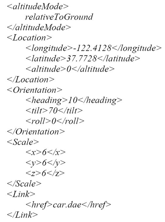
The key format of KML is as below:
5. Conclusions
The basic principles of GE-based URAV simulation train ing method and its realization process are presented in the paper. A visual control interface is edited by Visual C++ 6.0 and it passes the test in laboratory, which is displayed as in Figure 9.
The method can realized the simulation of different UAV through changing 3D simulation models of UAV and the data of serial interface, therefore the method has strong portability and adaptability. The system provides a more vivid operation environment and visual scene. Flight simulation in different terrains can be realized by making use of large number of scenes in GE, so it can
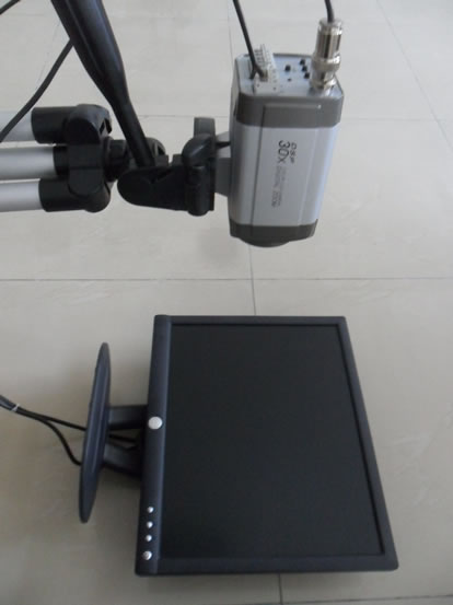
Figure 9. Testing environment of lab.
avoid repetitive training. It also can help operators to familiarize relevant terrain in the training process, therefore the reality and indulgence of training is strengthened. Various complicated tasks are produced through SketchUp model. By making use of current 3D models, the workload of modeling are reduced through form transformation and it provides good reference to objects’ tracking and fire correction. The method describes flight process vividly, which contributes to the evaluation of operators’ training and increases training efficiency.
REFERENCES
- T. J. Hing and P. Y. Oh, “Development of an Unmanned Aerial Vehicle Piloting System with Integrated Motion Cueing for Training and Pilot Evaluation,” Journal of Intelligent and Robotic Systems, Vol. 54, No. 13, 2009, pp. 3-19. doi:10.1007/s10846-008-9252-3
- Y. Wang, W. Zhang, S. Wu and Y. Guo, “Simulators for Driving Safety Study—A Literature Review,” Lecture Notes in Computer Science, Vol. 45, No. 1, 2007, pp. 584- 593. doi:10.1007/978-3-540-73335-5_63
- B. Ji, G. L. Shan and H. Chen, “Visual Simulation Method Based on VRML and Target Track,” Journal of System Simulation, Vol. 23, No. 9, 2011, pp. 1900-1904.
- G. D. Jin, L. B. Lu and Y. L. He, “URAV Real-Time Simulation System,” Journal of System Simulation, Vol. 19, No. 13, 2007, pp. 2932-2935.
- B. J. Yao, H. Zhao, C. L. Li and M. C. Chen, “3D Huge Terrain Generation in Flight Scene Simulation,” Journal of System Simulation, Vol. 21, No. 6, 2009, pp. 1633-1636.
- Z. H. Qi, D. W. Hu, A. L. Liu and X. P. Hu, “Airborne IMU Simulation Based on Simulink and Flight Gear,” Journal of Chinese Inertial Technology, Vol. 16, No. 4, 2008, pp. 400-403.
- J. Li, X. M. Li, K. C. Qian and H. X. Zhou, “Motion State Estimation for Micro UAV Using Inertial Sensor and Stereo Camera Pair,” Acta Aeronautica et Astronautica Sinica, Vol. 32, No. 12, 2011, pp. 2310-2317.
- J. N. Wu and W. Wang, “Research of a Kind of New UAV Training Simulator Based on Equipment Simulation,” Computer Measurement & Control, Vol. 19, No. 12, 2011, pp. 3105-3107.
- C. D. Edwards, “Nonlinear Six Degree-of-Freedom Simulator for a Small Unmanned Aerial Vehicle,” Mississippi State University, Mississippi, 2010.
- G. Ye, Z. F. Tian and C. L. Yan, “Flight-Test Data Visualization of Aircraft’s Flight Course Based on OpenGL,” Acta Aeronautica et Astronautica Sinica, Vol. 32, No. 6, 2011, pp. 1050-1057.
- E. Sun, A. Nieto and Z. Li, “GPS and Google Earth Based 3D Assisted Driving System for Trucks in Surface Mines,” Mining Science and Technology, Vol. 20, No. 1, 2010, pp. 138-142.
- Google Earth COM API Documentation. http://earth google.com/comapi/
- Keyhole Markup Language Documentation Introduction. http://code.google.com/api/kml/documentation/
- J. Ma, “Ground Monitor and Control System for Unmanned Aerial Vehicle Based on Google Earth,” Nanjing University of Aeronautics and Astronautics, Nanjing, 2011.
- J. P. Dai, “3D Visualization Technology Based on Google SketchUp,” Science of Surveying and Mapping, Vol. 36, No. 5, 2011, pp. 231-233.
NOTES
*Corresponding author.