Journal of Biomaterials and Nanobiotechnology
Vol.3 No.2A(2012), Article ID:18987,6 pages DOI:10.4236/jbnb.2012.322034
Numerical Investigation of Traveling Wave Electroosmotic Flows in a Microchannel*
![]()
Mechanics Department, Huazhong University of Science and Technology, Wuhan, China.
Email: wujkang@mail.hust.edu.cn
Received January 29th, 2012; revised February 28th, 2012; accepted March 10th, 2012
Keywords: Traveling-Wave Electroosmotic Flow (TWEF); Coordinate Transformation Method (CTM); Electric Double Layer (EDL); Poisson-Nernst-Planck (PNP) Equations
ABSTRACT
In this paper, a coordinate transformation method (CTM) is employed to numerically solve the Poisson-Nernst-Planck (PNP) equation and Navier-Stokes (NS) equations for studying the traveling-wave electroosmotic flow (TWEF) in a two-dimensional microchannel. Numerical solutions indicate that the numerical solutions of TWEF with and without the coordinate transformation are in good agreement, while CTM effectively improves stability and convergence rate of the numerical solution, and saves computational cost. It is found that the averaged flow velocity of TWEF in a microchannel strongly depends on frequency of the electric field. Flow rate achieves a maximum around the charge frequency of the electric double layer. The approximate solutions of TWEF with slip boundary conditions are also presented for comparison. It is shown that the NS solution with slip boundary conditions agree well with those of complete PNP-NS equations in the cases of small ratios of Electric double layer (EDL) thickness to channel depth (λD/H). The NS solution with slip boundary conditions over-estimates the electroosmotic flow velocity as this ratio (λD/H) is large.
1. Introduction
Microfluidics has emerged as a new area of multiphysical research associated with fluid mechanics, biology, chemistry and electricity [1]. Microfluidic devices have extensive applications in biochemical and biomedicical analyses. Electroosmotic microfluidic chips have many advantages such as easy fabrication, low costs, and high reliability. Electroosmotic flows (EOF) have been increasingly recognized as an efficient fluid transport/manipulation mechanism in microfluidic chips [2]. Good understanding of electrokinetic flow behaviors is required for the optimal design of electroosmotic microfluidic devices. Most solid surfaces acquire an electric charge when brought into contact with electrolyte solutions. The charged wall surface attracts counter-ions and repels co-ions in the liquid. As a result, there is an excess of counter-ions over co-ions in a thin liquid layer near the solid wall. This thin and charged liquid layer is called the Electric double layer (EDL) [3,4]. Electroosmosis (EOF) is the charged liquid flow relative to the stationary wall surface under an electric field applied at a tangent to the wall. A lot of studies, such as [5-8] have been devoted to EOF in microchannels with DC electrical fields where a high voltage is usually required. Recently, electroosmotic flows driven by AC electrical fields with asymmetry electrodes have been studied [9-12]. It is found that the AC field with low voltage can produce directional electroosmotic flow rates in a microchannel, but the flow rate is small. Ramos [13-16] also found directional flow rates of electroosmotic flows in a microchannel driven by traveling wave electrical fields. A group of discrete electrodes are embedded beneath the solid wall and electrically insulated from the liquid. A traveling wave electrical field can be created by applying AC voltage of the same amplitude and frequency on all electrodes, and a lag phase angle is imposed between two neighboring electrodes in sequence. Traveling-wave electroosmotic flow (TWEF) is a nonlinear electrokinetic flow phenomenon. The traveling wave electric field attracts/repulses ions periodically to induce charge density inside the channel. The electric force on the fluid ρeE is a nonlinear interaction between the applied electric field and induced charge density. It is called induced charge electroosmosis (ICEO) [17]. Experimental study [13] showed that the averaged electroosmotic flow velocity of TWEF in a microchannel achieves a maximum around the charge frequency of EDL. Exact analytic solutions of TWEF in a microchannel have not been available. Numerical solution is also difficult because of the locally high gradient near the solid wall and multiphysical interactions of fluid flow, electricity and ion migration. Furthermore, the gradient is much greater in the direction perpendicular to the wall (transverse direction) than that in the direction tangent to the wall (longitudinal direction). Therefore, a refined grid is needed in the region near the wall. However, the grid size in the transverse direction may be much smaller than that in the longitudinal direction. Such kind of grid often leads to poor numerical solutions. It is difficult to manage numerical convergence and grid refinement. The coordinate transformation method (CTM) [18] is one of the effective methods for solving complex electrokinetic flows. CTM amplifies EDL thickness and does not change computational domain, so that numerical convergence can be greatly improved. The numerical solutions in a transformed system with a coarse grid can be as accurate as those in a non-transformed system with a refined grid. The objective of this study is to use CTM for numerical investigation of TWEF behaviors based on complete electrokinetic equations and to make comparison with approximate NS solutions with slip boundary conditions.
2. Physical and Mathematical Description of TWEF in a Microchannel
A two-dimensional microchannel with embedded electrodes is shown in Figure 1. A group of discrete micro-electrodes is embedded on the bottom wall of the channel. Electrodes are insulated from the liquid. No electrode is on the top wall of the channel that is electrically insulated. A traveling wave electrical field can be created by applying AC voltage on all electrodes with the same amplitude and frequency, but a lag phase exists between every two neighboring electrodes. The traveling wave electric potential on the bottom wall can be approximately expressed by , where, V0, ω, k are the amplitude, angle frequency and wave number of the traveling wave, respectively.
  is the physical frequency, and
 , where L is the wave length. It is expected that the traveling wave electroosmotic flow behaves periodically in the longitudinal direction of the channel (x), thus a part of the channel (L × H) is needed for numerical analysis, as shown in Figure 1, where H is the channel depth. The microchannel is filled with a symmetrical electrolyte solution.

Figure 1. Sketch of a two-dimensional microchannel with traveling wave electroosmotic flows.
3. Governing Equations and Boundary Conditions of TWEF in THE Microchannel
The continuity equation and Navier-Stokes (NS) equation for incompressible fluid flow read as:
 . (1)
. (1)
 . (2)
. (2)
where, V is velocity, ρ is fluid density, μ is dynamic viscosity of the fluid, p is pressure, and ρe is the volume charge density of the solution. The last term in Equation (2) (–ρeΔΨ) is the electric force acting on the fluid, where Ψ is electrical potential. No-ship boundary conditions on channel walls and periodical flow conditions at the inlet and outlet of the channel are imposed. The electric potential of TWEF is governed by the Poisson equation [1]
 . (3)
. (3)
where c+, c– are mole concentrations of positive and negative ions, respectively, ε is solution permittivity, and F is Faraday’s constant. The traveling wave electric potential on the bottom wall of the channel is
 . (4)
. (4)
and
 . (5)
. (5)
on the insulated top wall. Periodic conditions of the potential Ψ at inlet and outlet of the channel are imposed. The ion concentrations are governed by the PoissonNernst-Planck (PNP) equations reflecting charge conservation law.
 . (6)
. (6)
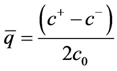
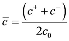
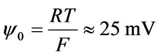
where D is ion diffusivity, R is the gas constant, T is the absolute temperature, zi is the ion valence, and Ji is the ion flux. Furthermore, n·Ji = 0 on the channel wall, and periodic conditions of ion concentration are imposed at inlet and outlet of the channel. In general, the dimensionless flow variables are defined as follows:
 ,
,  ,
,  ,
,  ,
,
 . (7)
. (7)
 ,
,  ,
,  ,
,  ,
,
 ,
, . (8)
. (8)
 ,
,  ,
,  ,
,  ,
,
 ,
,  ,
, . (9)
. (9)
where,  is the characteristic thickness of the electric double layer, ε and σ are permittivity and electric conductivity of the solution, respectively, and c0 is the ion concentration of the bulk solution.
Dimensionless Poisson equation is written as:
 . (10)
Dimensionless Nernst-Planck equation reduces to
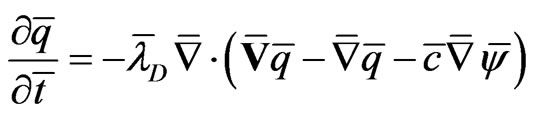 . (11)
 . (12)
Dimensionless Navier-Stokes equation is written as:
 . (13)
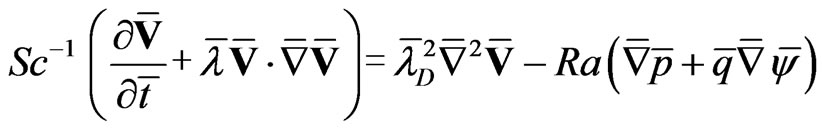 . (14)
where, 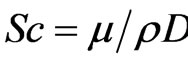 ,
, . Equations (10)-(14) are the dimensionless coupled governing equations of TWEF in a microchannel.
Coordinate Transformation Method for TWEF in a Microchannel
Coordinate transformation is introduced by defining
 ,
,  ,
, . (15)
where ,
,  ,
,  in Equations (10)-(14) are expressed as:
 ,
, . (16)
where, 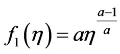 ,
,  ,
,
 . (17)
Poisson Equation (10) in the transformed coordinate system  is written as:
 . (18)
where, .
.
Nernst-Planck Equations (11)-(12) in the  system are written as:
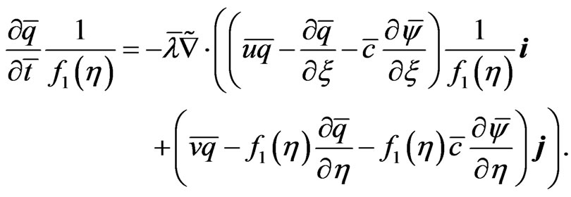 (19)
(19)
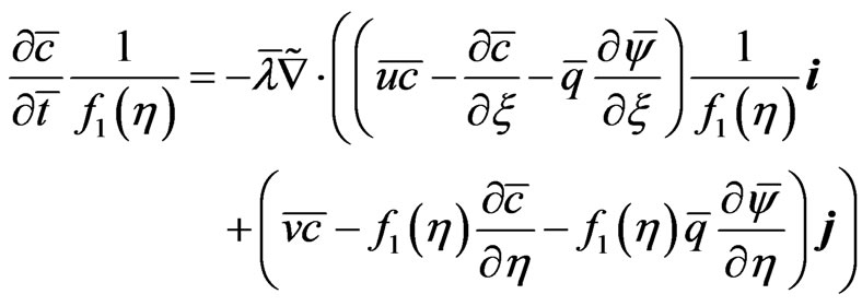 . (20)
Flow Equations (13)-(14) in the  system are written as:
 . (21)
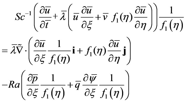 . (22)
 . (23)
4. Numerical Example and Discussion
Typical microchannel geometric data and physica1 parameters are given as follows. The computational channel length and depth are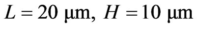 , as shown in Figure 1, ρ = 993.3 kg/m3, c0 = 10–2 mol/m3, μ = 6.919 × 10⁻⁴ Pa/s, T = 310 K, ε = 7.2036 × 10⁻¹⁰ F/m, F = 96,490 C/mol, R= 8.314 J/(k·mol), λD = 100 nm, D = 2 × 10⁻⁹ m2/s, c0 = 10–2 mol/m3, U0 = 2 × 10⁻⁴ m2/s, σ = 1.45 × 10⁻⁴ (mS)/m, a = 0.2 in coordinate transformation Equation (15). Averaged TWEF velocity is defined as
 , where P is the period of TWEF. Dimensionless averaged velocity is defined as
 . COMSOL Multiphysics was used to solve TWEF Equations (18)-(23) in the transformed system (
 ) and Equations (10)-(14) in the physical system (
 ). To validate our numerical solutions, an approximate solution of the NS equations with electroosmotic slip velocity boundary conditions is also presented for comparison with that of the complete TWEF equations. When the voltage amplitude of the traveling wave electric field is low, and the ratio of EDL thickness to channel depth (
 ) is small, the effects of EDL on the electrokinetic flow can be replaced by a local slip velocity
  [9-11]. It is called Helmholtz-Smoluchowski velocity, where ξ and E are the local wall zeta potential and wall electric field intensity, respectively. This velocity serves as the slip boundary condition when solving the NS equations without solving Poisson-NernstPlanck (PNP) equations [19]. This slip boundary model simplifies numerical computation, but it may produce errors. The local grids close to electrodes in the physical system and transformed system are shown in Figure 2 and Figure 3. The total number of grids in the transformed system is much smaller than that in the physical system.
Figure 4 to Figure 7 show effects of the TWEF frequency on the averaged flow velocity. Dimensionless frequency is defined as 

 , where
  is the charge time scale of EDL in the microchannel. Numerical results indicate that averaged electroosmotic velocity looks like Gaussian distribution with respect to the electric field frequency, and achieves a maximum around
 , corresponding to the charge time of the electric double layer in the micro-

Figure 2. Local grid near the wall in physical system, total 800 finite-elements.

Figure 3. Local grid near the wall in transformed system, total 200 finite-elements.

Figure 4. Averaged electroosmotic velocity versus electric frequency .
.

Figure 5. Averaged electroosmotic velocity versus electric frequency .
.

Figure 6. Averaged electroosmotic velocity versus electric frequency .
.
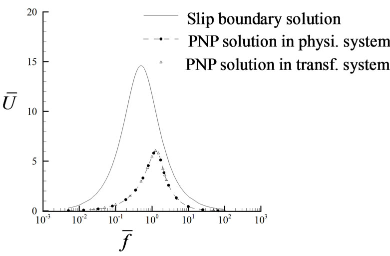
Figure 7. Averaged electroosmotic velocity versus electric frequency .
.
channel. The averaged velocity behavior is consistent with experimental results [16]. It can be seen, from Figure 4, that the numerical solutions with and without coordinate transformation are in good agreement. The slip boundary solution also agrees with that of the complete PNP equations, but the peak value is slightly larger. In this case, both the voltage amplitude of the electric field and EDL thickness are small,  ,
,  ,
, 
 = 0.01.
In the case of large voltage applied on the electrodes ( ) in Figure 5, it can be seen that the averaged velocity increases with the increase of the voltage amplitude of the electric field, and the peak frequency(when velocity is maximum ) of the PNP solution is slightly lower than that of the slip boundary solution. In the case of large voltages, the slip boundary solution is less accurate. In the case of a shallow channel and small wall voltage (
 ,
, ) in Figure 6, the slip boundary solution over-estimates the flow velocity. The error is about 60% relative to that of the PNP solution. In the case of a shallow channel and high applied voltage (
 ,
, ) in Figure 7, it can be seen that the slip boundary solution leads to a considerable error both in the flow velocity and the peak frequency. The slip boundary approximation is not valid for relatively large ratio of
 , and complete PNP-NS equations have to be used which accurately describe the multiphysical interaction between the fluid flow, electricity and ion transport in the microfluidic system.
The effects of EDL thickness (dependent on fluid properties) on the electroosmotic flow velocity is illustrated in Figure 8. It can be seen that averaged flow velocity decreases with the increase of the EDL thickness ( ). In addition, the slip boundary solution is accurate for small
 , and over-estimates flow velocity as
  is large.
The effects of wave length of TWEF on the electroosmotic flow velocity is shown in Figure 9 where 
 . It can be seen that when the wave length increases the averaged velocity decreases and the peak frequency is shifted to lower values.
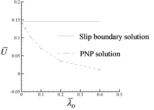
Figure 8. Averaged electroosmotic velocity versus ,
, 

Figure 9. Averaged electroosmotic velocity versus electric frequency .
.
5. Conclusions
The numerical investigation of traveling wave electroosmotic flows (TWEF) in a microchannel is carried out in this study using a coordinate transformation method, based on fully coupled nonlinear Poisson-Nernst-Planck equations and Navier-Stokes equations. Conclutions are summarized as follows.
1) Grid refinement is required for accurate numerical solution due to high gradients of TWEF near the solid wall and multiphysical interactions between fluid flow, electricity and ion transport. The coordinate transformation method adopted in this study effectively decreases gradients of flow variables and improves stability and convergence. The numerical solutions in the transformed system with a coarse grid can be as accurate as those in the physical system with a refined grid.
2) Averaged velocity of TWEF in the microchannel behaves like a Gaussian distribution with respect to the electric field frequency, and achieves a maximum when the frequency of TWEF approaches the charge frequency of the electric double layer, i.e., . The averaged velocity is small as the electric frequency is far away from the charge frequency. The averaged velocity decreases when EDL thickness in the microcannel or the wave length of TWEF increases.
3) Slip boundary model simplifies numerical computation of TWEF in the microchannel. The slip boundary solution is accurate in the case of small ratio of EDL thickness to channel depth, and over-estimates averaged TWEF velocity when the ratio ( ) is large.
REFERENCES
- D. Li, “Electrokinetics in Microfluidics: Interfaces Science and Technology,” 1st Edition, Academic Press, New York, 2004.
- M. S. Yoon, B. J. Kim and H. J. Sung, “Pumping and Mixing in a Microchannel Using AC Asymmetric Electrode Arrays,” International Journal of Heat and Fluid Flow, Vol. 29, 2008, pp. 269-280. doi:10.1016/j.ijheatfluidflow.2007.10.002
- J. Lyklema, “Fundamentals of Interface and Colloid Science,” 1st Edition, Academic Press, New York, 1995.
- R. J. Hunter, “Zeta Potential in Colloid Science,” 1st Edition, Academic Press, New York, 1981.
- Y. Zhen and L. G. Anthony, “Electrokinetic Transport and Separations in Fluidic Nanochannels,” Electrophoresis, Vol. 28, No. 4, 2007, pp. 595-610. doi:10.1002/elps.200600612
- J. M. Edwards and M. N. Hamblin, “Thin Film Electroosmotic Pumps for Biomicrofluidic Applications,” Biomicrofluidics, Vol. 1, No. 1, 2007, Article ID 014101.
- A. L. Margaret and C. J. Stephen, “Electrokinetic Fluid Control in Two-Dimensional Planar Microfluidic Devices,” Analytical Chemistry, Vol. 79, No. 19, 2007, pp. 7485-7491. doi:10.1021/ac071003y
- G. E. Karniadakis and A. Beskok, “Micro Flows: Fundamentals and Simulation,” Springer-Verlag, New York, 2002.
- D. B. Pengra, S. L. Li and P. Wong, “Determination of Rock Properties by Low Frequency AC Electrokinetics,” Journal of Geophysical Research, Vol. 104, No. B12, 1999, pp. 29485-29508. doi:10.1029/1999JB900277
- H. K. Yang, H. Y. Jiang, et al., “AC Electrokinetic Pumping on Symmetric Electrode Arrays,” Microfluid and Nanofluid, Vol. 7, 2009, pp. 767-772.
- A. Ramos, A. Gonzalez, A. Castellanos, et al., “Pumping of Liquids with AC Voltages Applied to Asymmetric Pairs of Microelectrodes,” Physical Review E, Vol. 67, No. 5, 2003, Article ID 056302. doi:10.1103/PhysRevE.67.056302
- M. Pribyl, K. Adamiak, et al., “Numerical Models for AC Electro-Osmotic Micropumps,” IEEE Industry Applications Society Annual Meeting, Edmonton, 5-9 October 2008, pp. 1870-1877.
- A. Ramos, H. Morgan, N. G. Green, et al., “Pumping of Liquids with Traveling-Wave Electroosmosis,” Journal of Applied Physics, Vol. 97, No. 8, 2005, Article ID 084906. doi:10.1063/1.1873034
- A. Ramos, A. Gonzalez, P. Garcia-Sanchez, et al., “A Linear Analysis of the Effect of Faradaic Currents on Traveling-Wave Electroosmosis,” Journal of Colloid and Interface Science, Vol. 309, No. 2, 2007, pp. 323-331. doi:10.1016/j.jcis.2007.01.076
- A. Gonzalez, A. Ramos and A. Castellanos, “Pumping of Electrolytes Using Traveling-Wave Electro-Osmosis: A Weakly Nonlinear Analysis,” Microfluid and Nanofluid, Vol. 5, 2008, pp. 507-515. doi:10.1007/s10404-008-0261-0
- P. Garcia-Sanchez and A. Ramos, “The Effect of Electrode Height on the Performance of Traveling-Wave Electroosmotic Micropumps,” Microfluid and Nanofluid, Vol. 5, 2008, pp. 307-312. doi:10.1007/s10404-007-0247-3
- M. Z. Bazant and T. M. Squires, “Induced-Charge Electrokinetic Phenomena: Theory and Microfluidic Applications,” Physical Review Letters, Vol. 92, No. 6, 2004, Article ID 066101. doi:10.1103/PhysRevLett.92.066101
- Y. Zhang, J. K. Wu and B. Chen, “A Coordinate Transformation Method for Numerical Solutions of the Electric Double Layer and Electroosmotic Flows in a Microchannel,” International Journal for Numerical Methods in Fluids, Vol. 68, No. 6, 2012, pp. 671-685. doi:10.1002/fld.2527
- J. Hrdlicka, P. Cervenka, M. Pribyl and D. Snita, “Mathematical Modeling of AC Electroosmosis in Microfluidic and Nanofluidic Chips Using Equilibrium and Non-Equilibrium Approaches,” Journal of Applied Electrochemistry, Vol. 40, No. 5, 2010, pp. 967-980. doi:10.1007/s10800-009-9966-3
NOTES
*Supported by the National Science Foundation of China, Grant No. 11172111 and the Ph.D. Programs Foundation of Ministry of Education of China, Grant No. 20090142120007.