Journal of Minerals and Materials Characterization and Engineering
Vol.1 No.3(2013), Article ID:31720,6 pages DOI:10.4236/jmmce.2013.13018
Effect of Heat Treatments on Corrosion of Welded Low-Carbon Steel in Acid and Salt Environments
1Department of Metallurgical and Materials Engineering, Federal University of Technology, Akure, Nigeria
2Department of Mineral Resources Engineering, Federal Polytechnic, Ado-Ekiti, Nigeria
Email: *seidu2@yahoo.co.uk
Copyright © 2013 Saliu Ojo Seidu, Bolarinwa Johnson Kutelu. This is an open access article distributed under the Creative Commons Attribution License, which permits unrestricted use, distribution, and reproduction in any medium, provided the original work is properly cited.
Received March 18, 2013; revised April 20, 2013; accepted April 28, 2013
Keywords: Low-Carbon Steel; Heat Treatments; Microstructure; pH
ABSTRACT
Effect of heat treatment on the corrosion of welded low-carbon steel in 0.3 M and 0.5 M of hydrochloric acid and sodium chloride environments at ambient temperature (25˚C) has been investigated. Arc welded low-carbon steel sample of known composition were subjected to the corrosion reagents for 21 days (504 hours). pH and weight loss values were taken at interval of 3 days. Thereafter, weight loss method was used to measure the rate of corrosion attack on the heat treated samples at ambient temperature. Results obtained showed that at low concentration, the annealed sample exhibits better corrosion characteristic as compared to the normalized and quenched samples. However, at higher concentration the normalized sample exercised better service performance over the annealed and quenched samples. The quenched sample was found to have relatively low corrosion performance over the annealed and normalized samples at both low and high concentrations of the media.
1. Introduction
Carbon steels are the most important alloys used in petroleum and chemical industries since they account for over 98% of the construction materials. Among the most widely used of these alloys is low-carbon steel, its wide range of applications such as chemical, oil gas storage tanks and transportation pipelines is due to its moderate strength, good weldability and formability [1]. However, this material is susceptible to corrosion when used in chemical and sour crude oil environments.
Pipelines deterioration as a result of corrosion has come to be accepted worldwide as an unavoidable fact of life. 2241 major pipeline accidents were reported [2] in the United Kingdom (UK) in the last 10 years and in the US alone the lost number on corrosion is approaching 350 million dollar per year [3]. In Nigeria, petroleum pipeline explosions occur regularly resulting in loss of lives and environmental pollution. There was a report of pipeline explosion in Idjerhe (Jesse) where hundreds of lives were lost [4]. A related incident in Adeje village near Warri, Delta State, where more than 250 Nigerians were fared died [5].
The present degradation of infrastructures particularly in the salt and acid environments has continued to generate a lot of worries to the researchers in this noble area in the view to procure lasting solution to the problem. Metallurgical control of corrosion includes inhibition, coating and heat treatments [6]. Over the years, inhibition and coatings have been the two major methods of corrosion control. Therefore, in this work attention is paid to heat treatment method of corrosion control.
Heat treatment is a method of altering the physical and sometimes chemical properties of materials. The most recent study of cost of materials lost to corrosion in the United Kingdom carried out by the government committee on corrosion and protection was put at a staggering rate of £350 billion per annum. Corrosion, like taxes and death is inevitable especially in the chemical and petroleum industries [7]. Hence, if one considers the enormous amount of money spent in combating corrosion and the attendant grievous consequences of corrosion disasters then, this work is a right step in the right direction. Hence, studies were carried out on how the corrosion characteristics of welded low-carbon steel can be improved upon through quenching, normalizing and annealing heat treatment routes with a view to obtaining best route(s) for optimum service performance in acid and salt media at varied concentrations.
2. Materials and Method
2.1. Materials
The materials used for this work are low carbon steel in form of a plate of 10 mm thickness, multi-purpose electrode (gauge 10) and corrosion reagents.
2.2. Method
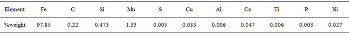
The chemical analysis of the “as-received” low-carbon steel sample was conducted by optical emission spectrometry with an AR430 metal analyzer. The chemical composition is shown in Table 1.
Specimen of dimension 10 × 10 × 10 mm was cut from the original sample with hack saw, polished with 240, 320, 400, 600, 1000 and 1200 grits of emery papers respectively and etched with 2% nital solution. Microscopy studies were then carried out on the prepared sample using optical microscope at magnification of 400×.
2.3. Welding
Twenty (20) samples of 10 × 10 × 10 mm dimension were cut from the remaining steel plate using hack saw, the samples were then divided into four (4) groups A, B, C and D with each group having five samples. Samples in group A serves as control while samples in groups B, C and D were welded using electric arc welding with general purpose electrode (gauge 10).
2.4. Heat Treatment
All the welded samples were stress relieved to remove internal stresses imposed on them during welding [8]. They were then heated to a temperature of 650˚C, soaked for 30 minutes and allowed to cool in the furnace to ambient temperature (25˚C). Samples B were then subjected to normalizing treatment by heating them to 920˚C soaked for 30 minutes and cooled in still air to ambient temperature.
Samples C were annealed by heating them to 920˚C soaked for 30 minutes and cooled in the furnace to ambient temperature. Samples D were heated to 920˚C soaked for 30 minutes and cooled in water at ambient temperature. All the heat treatment samples were prepared for metallographic analysis; they were consecutively polished with emery papers of grades 240, 320, 400, 600, 1000 and 1200 grits to remove scales resulting from heat treat processes.
2.5. Preparation of Corrosive Media
Corrosive media of Conc. HCl and Conc. NaCl were prepared with 0.3 M and 0.5 M. Thereafter, the welded and the non-welded heat treatment samples were exposed to the media for 21 days (504 hours) for corrosion attacks. Weight loss—a measure of difference between the original mass of the sample before immersion (M1) and the mass of the same sample after exposure (M2) was taken at interval of 3 days and corrosion rate in mil per year is calculated using the recommended ASTM relation Corrosion rate = W/A·(T/365)
where:
W = Weight loss (gram);
A = Total area of exposure (cm2);
T = Exposure time in hours;
g/mm2/yr = gram per square mm per year (corrosion rate units).
pH was measured on daily basis for 21 days (504 hours) using Buffer tablets stabilized pH meter.
3. Results
3.1. Assessment of Corrosion Attack on the Test Samples
Corrosion action on the test samples were assessed by visual observation and corrosion rate measurement. Formation of corrosion products (light-green colour material) on the surfaces and the edges of the steel samples was observed to have occurred after 24 hours of exposure, but much earlier in samples attacked by 0.5 M and 0.3 M of Conc. HCl. Areas of attack on the samples by the environments were visually observed to be more for the quenched sample as compared to the normalized and annealed samples, and the oxidation products were observed to be uniformly laid on the samples’ surfaces and edges.
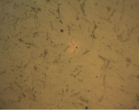
3.2. Optical Microscopy Study
Optical microscopy study of the “as-received” nonwelded low carbon steel (Figure 1(a)) revealed predominantly pearlite phase in a matrix of ferrite. The dark areas correspond to pearlite and light areas depict the ferrite phase.
Figure 1(b) revealed the microstructure of the “as-received” welded stress relieved sample after corrosion attack. Visibly present are dark areas corresponding to
Table 1. Chemical composition of the “as-received” low-carbon steel.
pearlite phase and light areas corresponding to ferrite phase. Some dark spots are also seen in the matrix.
Figure 1(c) is the microstructure of welded normalized sample. Pearlite and ferrite are the two phases present with the volume of pearlite occuring more as compared to ferrite.
Figure 1(d) shows microstructure of welded annealed sample, pearlite and ferrite are the two phases present with more volume of ferrite as compared to pearlite. Grain size of normalized structure is seen to be smaller than that of the corresponding annealed structure.
Figure 1(e) shows optical microstructure of welded quenched sample, visibly present are pearlite and ferrite phases with more volume of pearlite as compared to ferrite. Some dark spots are also present while the grain size of quenched structure is smaller as compared to both the normalized and annealed structures.
3.3. Cummulative Weight Loss
Figure 2 shows plot of samples cumulative weight loss against time of exposure in 0.3 M of sodium chloride solution. It is observed that the samples lose weight with
 (a)
(a)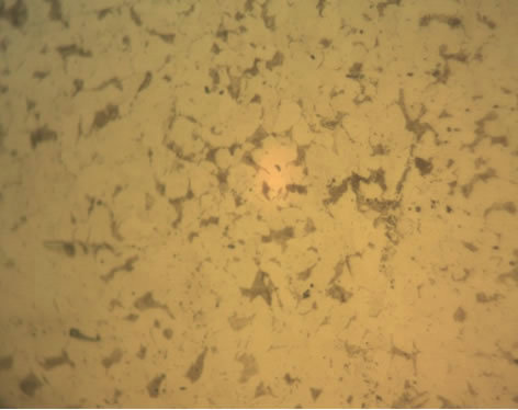 (b)
(b) (c)
(c) (d)
(d) (e)
(e)
Figure 1. Optical microstructures of (a) Non welded as-received; (b) Welded as-received; (c) Welded normalized; (d) Welded annealed; and (e) Welded quenched samples at magnification 400×.
increasing exposure time; trend of weight loss is in increasing order of annealed, quenched, as-received and normalized samples.
Figure 3 is a plot of cummulative weight loss of the samples against exposure time in 0.5 M sodium chloride. The as-received and quenched samples were seen to lose weight at almost the same rate, while the normalized and annealed samples, there occurs a significant rate of weight loss for the normalized sample as compared to the annealed sample. A relatively significant difference in rate of weight loss is observed.
Figure 4 shows weight loss characteristic of the samples over exposure time in 0.3 M of HCl. The normalized, quenched and annealed samples were found to exhibit an initial gradual weight loss. On further exposure to the environment, a rather constant weight loss is observe and between exposure time range of 4881 hours and 504 hours, the normalized, quenched and as-received samples showed constant weight loss, while the annealed sample revealed the highest weight loss value.
Cummulative weight loss of the samples in 0.5 M HCl over the exposure time is shown in Figure 5. For the normalized, annealed and quenched samples, an initial sharp increase weight loss between 72 - 278 hours of exposure is observed. Subsequently, a gradual increase

Figure 2. Cummulative weight loss with time of exposure in 0.3 M sodium chloride.
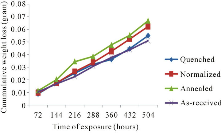
Figure 3. Cummulative weight loss with time of exposure in 0.5 M sodium chloride.
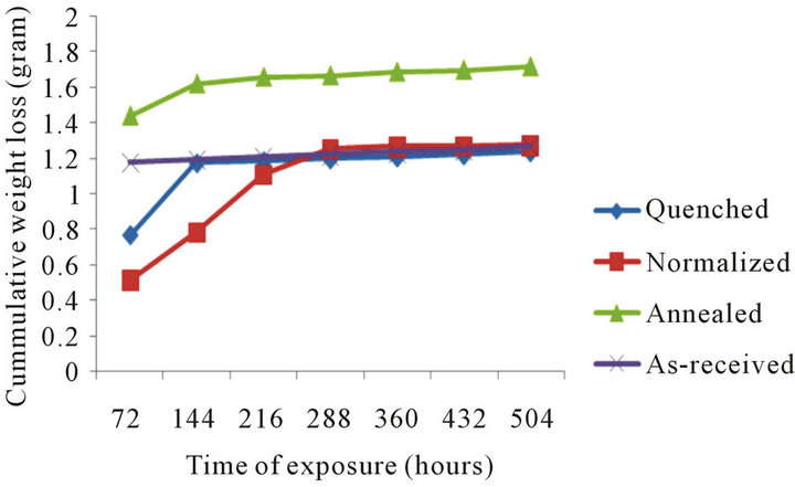
Figure 4. Cummulative weight loss with time of exposure in 0.3 M hydrogen chloride.
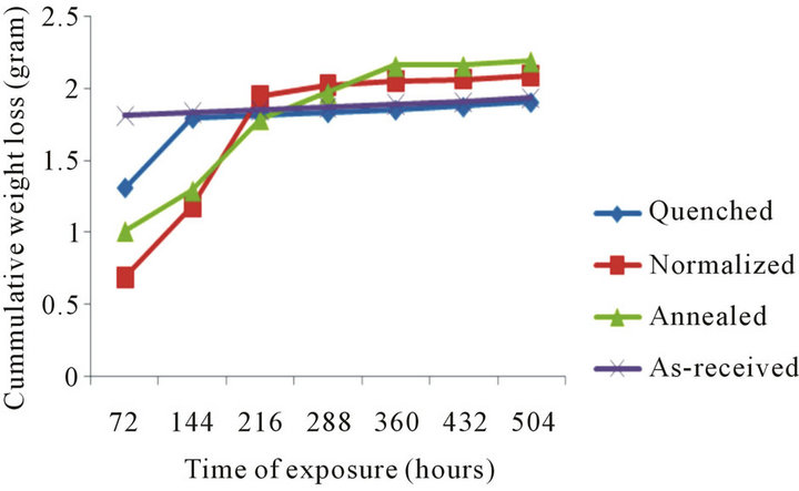
Figure 5. Cummulative weight loss with time of exposure in 0.5 M hydrogen chloride.
up to 504 hours is noticed, the normalized sample shows less initial weight loss as compared to the annealed and quenched samples, with increasing time of exposure, the annealed sample is found to lose weight more rapidly relative to the quenched and normalized samples. The as-received sample shows a constant weight loss from the initial to the final stage of exposure time.
3.4. pH
Figure 6 is a plot of the pH against time of exposure for samples in 0.3 M of NaCl solution, the plot revealed marginal incremental difference in pH of all the samples with incresing time of exposure.
Plot of the samples pH against time of exposure in 0.5 M of NaCl solution is given in Figure 7; unlike for 0.3 M of NaCl solution, the plot is characterized by sharp increase in pH with the annealed sample exhibiting highest pH value as compared to the normalized, quenched and as-received samples.
Plot of pH against exposure time for samples in 0.3 M of HCl is seen in Figure 8" target="_self"> Figure 8. The pH is found to increase with increasing exposure time with the quenched sample exhibiting highest pH value as compared to the normalized, annealed and as-received samples.

Figure 6. pH with time of exposure of samples in 0.3 M NaCl.

Figure 7. pH with time of exposure of samples in 0.5 M NaCl.
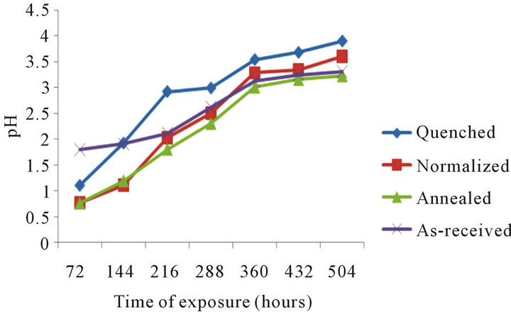
Figure 8. pH with time of exposure of samples in 0.3 M HCl.
Figure 9 shows plot of pH against time of exposure of samples in 0.5 M of HCl, there is increase in pH value of the samples over the entire exposure time.
4. Discussion
The pearlite (dark) phase and ferrite (light) phase observed in the microstructure of the as-received sample (Figure 1(a)) may have resulted from the past history of the steel plate. The dark spots observed in the (Figure 1(b)) may be due to corrosion effects, the more fraction

Figure 9. pH with time of exposure of samples in 0.5 M HCl.
volume of ferrite in annealed condition (Figure 1(c)) may have resulted from phase transformation occuring during heat treatment, while the homogeneous dispersion of pearlite could have been due to size of austenite grains from which they were transformed [9].
The more fraction volume of pearlite obtained in the microstructure of normalized sample (Figure 1(d)) could be due to air cooling. The observed difference in grain size and phase distribution for the welded annealed, normalized and quenched samples (Figures 1(c), (d) and (e)) could be attributed to the effect of heat treatment. The rate of cooling from the austenite region affects grain size and (ferite-pearlite) phase distribution [10].
The observed increase in cummulative weight loss of the samples at constant temperature agrees with the observation earlier made that corrosion rate at constant temperature increases with increasing exposure time, while the observed variation in the weight loss of the sample may be attributed to difference in the samples grain size [11]. It was equally revealed that heat treatment affects rate of corrosion and posited that the bigger the grains of a material, the more are its resistance to corrosion [12]. Hence, the annealed sample with the biggest grain size distribution revealed less weight loss as compared to the normalized and quenched samples.
The observed increase in cummulative weight loss of the sample at increasing concentration (0.3 - 0.5 M) of the media is in agreement with the corrosion of aluminium in HCl [11]. It was showed that corrosion rate of aluminium increases considerably with increasing concentration, and the observed difference in the weight loss of the samples in HCl and NaCl solutions could be attributable majorly to difference in corrosivity of the environments. However the observed constant cummulative weight loss of the as-received sample throughout the exposure time may be due to formation of impevious layer which is generally known to be protective. The noticed spontaneous exponential increase in weight loss of the annealed sample has further showed that annealed sample may not have reasonable tolerance for corrosion in harsh environments.
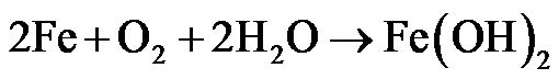
The observed characteristic increase in pH and corresponding decrease in corrosion rates of the samples in the acid and salt environments with increasing exposure time may be due to electrochemical behaviour of the various samples in the different environments. At high pH, hydrogen evolution is reduced and the possibility of protective film formation is increased such that as exposure time is increased the rate at which the samples corrode is reduced. The relatively lower rate of corrosion in aqueous solution may be due to formation of black surface, which is adherent, non-porous and uniformly lay on the metal [13]. This black product is magnetic (Fe2O3) and passivates very well. Hence, formation of protective film greatly reduces corrosion rate. Previous study [14] showed that the greater the alkalinity, the slower the rate of attack becomes. Also, in a related study [12] on the role of aqueous corrosion in the selection of water treatment parameters showed that corrosion reaction of mild steel in aerated environments (solutions) can be written as:
 (1)
(1)
He noted that at the initial stage of attack, the corrosions rate of the test sample is increased. As the exposure time is increased; there occurred formation of ferrous hydroxide film as barrier to oxygen diffusion. With continuous exposure of the sample to the environment iron(II) hydroxide is converted to iron(III) hydroxide and in the process the pH of the environment is raised.
5. Conclusion
From the results obtained, it is observed that the effectiveness of the heat tretment methods of corrosion control is largely dependent on the concentration of the various media. At low concnetration the annealed sample was found to have remarkable corrosion resistance, hence better service performance as compared to the normalized and quenched samples. While at higher concentrations, the normalized sample was found to exercise better service performance over the annealed and quenched samples. The quenched sample on the other hand is observed to have relatively low corrosion performance over the annealed and normalized sample at both low and high concentrations of the media.
REFERENCES
- T. Senthilkumar and T. K. Ajiboye, “Effect of Heat Treatment Processes on the Mechanical Properties of Medium Carbon Steel,” Journal of Minerals and Materials Characterization and Engineering, Vol. 11, No. 2, 2012, pp. 143-152.
- P. R. Roberge, “Hand Book of Corrosion Engineering,” McGraw-Hill Inc., New York, 2000, pp. 65-72.
- S. Nicholas, “Rust Is Risk,” Intech, USA, 2009.
- J. Trevor, “More than 250 Feared Dead in Nigeria Pipeline Explosion,” WSWS, News and Analysis Africa, 2005.
- M. A. Bodude, “Integrity Assessment of Locally Produced Low-Carbon Steel For Oil and Gas Transportation,” Ph.D. Thesis, Federal University of Technology, Akure, 2006.
- K. R. Trethewey and P. R. Roberge, “Corrosion Management in the Twenty-First Century,” British Corrosion Journal, Vol. 30, No. 3, 1995, pp. 192-197. doi:10.1179/000705995798113925
- O. O. Daramola, B. O. Adewuyi and I. O. Oladele, “Corrosion Behaviour of Heat Treated Rolled Medium Carbon Steel in Marine Environment,” Journal of Minerals and Materials Characterization and Engineering, Vol. 10, No. 10, 2011, pp. 888-903.
- A. V. Adedayo, S. A. Ibitoye and O. A. Oyetoyan, “Annealing Heat Treatment Effects on Steel Welds,” Journal of Minerals and Materials Characterization and Engineering, Vol. 9, No. 6, 2010, pp. 547-557.
- R. A. Higgins, “Engineering Materials and Applied Physical Metallurgy Part 1,” 6th Edition, Arnold Hodder Headline Group, 1993, pp. 31-33.
- Y. U. Lakhtin, “Engineering Physical Metallurgy and Heat Treatment,” MIR Publishers, Moscow, 1979, pp. 183-185.
- D. T. Oloruntoba, O. O. Oluwole and E. O Oguntade, “Comparative Study of Corrosion Behaviour of Galvanized Steel and Coated Al 3103 Roofing Sheets in Carbonate and Chloride Environments,” Materials and Design, Vol. 30, 2009, pp. 1371-1376.
- G. H. Aydogdu and M. K. Aydinol, “Determination of Susceptibility to Intergranular Corrosion and Electrochemical Reactivation Behaviour of AISI 316l Type Stainless Steel,” Corrosion Science, Vol. 48, 2006, pp. 3565- 3583.
- F. O. Aramide, E. O. Olorunniwo, P. O. Atanda and J. O. Borode, “Corrosion Characteristics of As-Cast Ductile Iron in Lime Juice,” Journal of Minerals and Materials Characterization and Engineering, Vol. 9, No. 10, 2010, pp. 867-877.
- A. S. Fouda, L. H. Madkour, A. A. El-Shafie and A. A. El-Asklany, “Inhibitory Effect of Some Carbazides on Corrosion of Aluminum in HCl and NaOH Solutions,” Materialwissenschaft und Werkstofftechnik, Vol. 26, No. 6, 1995, pp. 342-346.
NOTES
*Corresponding author.