International Journal of Medical Physics, Clinical Engineering and Radiation Oncology
Vol. 1 No. 2 (2012) , Article ID: 21749 , 10 pages DOI:10.4236/ijmpcero.2012.12007
A Hybrid Algorithm to Address Ambiguities in Deformable Image Registration for Radiation Therapy
1Department of Radiation Physics, The University of Texas MD Anderson Cancer Center, Houston, USA
2Scripps Proton Therapy Center, San Diego, USA
Email: yonzhang@mdanderson.org, songgao@mdanderson.org
Received June 4, 2012; revised July 10, 2012; accepted August 5, 2012
Keywords: Deformable Image Registration; Radial Basis Functions; Spline Registration; Image-Guided Radiotherapy; Auto-segmentation
ABSTRACT
We proposed the use of a hybrid deformable image registration approach that combines compact-support radial basis functions (CSRBF) spline registration with intensity-based image registration. The proposed method first uses the previously developed image intensity-based method to achieve voxel-by-voxel correspondences over the entire image region. Next, for those areas of inaccurate registration, a sparse set of landmark correspondences was defined for local deformable image registration using a multi-step CSRBF approach. This hybrid registration takes advantage of both intensity-based method for automatic processing of entire images and the CSRBF spline method for fine adjustment over specific regions. The goal of using this hybrid registration is to locally control the quality of registration results in specific regions of interest with minimal human intervention. The major applications of this approach in radiation therapy are for the corrections of registration failures caused by various imaging artifacts resulting in, low image contrast, and non-correspondence situations where an object may not be imaged in both target and source images. Both synthetic and real patient data have been used to evaluate this hybrid method. We used contours mapping to validate the accuracy of this method on real patient image. Our studies demonstrated that this hybrid method could improve overall registration accuracy with moderate overhead. In addition, we have also shown that the multi-step CSRBF registration proved to be more effective in handling large deformations while maintaining the smoothness of the transformation than original CSRBF.
1. Introduction
Deformable image registration is becoming an important tool for tracking changes in a patient’s anatomy during radiotherapy [1-9]. The image-intensity method [10] and the landmark method [11] are two main categories used in radiation therapy. Landmark-based registration requires the identification of a sparse set of control-point pairs in both the source and target images. Therefore, it is usually tedious, and subject to inter-observer variations in identifying landmark points. This is especially true for three-dimensional (3D) registration requiring identification of a large number of landmark points. On the other hand, image intensity-based registration usually can be done automatically using image intensity information as the sole input parameters. However, image intensitybased registration is subject to intensity variations caused by various imaging artifacts. Because little user input is required in the intensity-based registration process, correspondence ambiguity in image intensity can be a problem in certain situations [12]. Correspondence ambiguity may lead to unrealistic deformations, a typical example of which is low intensity contrast within the prostate and bladder region, where intensity-based registration tends to produce an unsatisfactory motion field owing to the lack of image features. The landmark-based registration algorithm is less dependent of the underlying image content than intensity-based approach if a set of key feature correspondences can be reliably defined. However, automatic and accurate building a large number of feature correspondences across an image pair is generally a tough problem, and manually labeling the correspondences can be extremely labor-intensive. In addition, the validity of landmark-based registration depends on the number and distribution of control points.
To improve the robustness and accuracy of deformable image registration in certain clinical situations, we have proposed a hybrid registration approach that combines the landmark-based method, using compact-support radial basis functions (CSRBFs) [13] with the intensity-based diffusion method [2,3]. In this hybrid approach, CSRBF spline registration was used to establish correspondences over in the local region defined by a sparse set of landmarks; while the regions distant away from landmarks were registered using the image intensitybased diffusion method. We used a multi-step strategy in our implementation of CSRBFs that can handle large geometric deformations.
Though some researchers have proposed combination of image intensity and landmarks for registration [14-18], the major difference is that they applied both image intensityand landmark-based registrations to the entire image and calculated the registration by optimization of global cost function. In our proposed method, the image intensity-based registration applies to the entire image; while the landmark-based registration applies only to a local region where accurate registration results cannot be achieved using intensity-based registration alone. We also proposed a multi-step CSRBF registration method that has proven to be robust in handling large deformations and insensitive to the registration parameters used.
2. Materials and Methods
2.1. Intensity-Based Diffusion Registration
Image intensity-based registration is also called voxel similarity-based registration because the registration metric and the cost function is calculated directly using the voxel-intensity values of the two images to be registered, i.e., source S(x) image and target T(x) image [10]. The registration process involves transforming the source image to best match the target image. The sum of squared-intensity differences (SSD) between source and target images is usually used in conjunction with a smoothness constraint, which can simulate various mechanical property of the material. For example, elastic image registration simulates the linear elastic material, and fluid image registration [19-21] simulates deformations in fluid dynamics. A generic diffusion-type image registration model can be constructed using the Tikhonov regularization constraint [2,3,17]. Thirion’s [22] demons registration algorithm [8,9] can be regarded as an approximation of the diffusion registration model using isotropic filtering.
We previously implemented a variational diffusion registration [2], where the displacement vector field uk (k = x, y, z in the Cartesian coordinate system) can be determined by solving the registration equation [2,3,17].
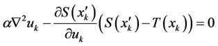 (1)
(1)
where a is the smooth parameter; S(xk) and T(xk) are the source and target image intensities, respectively; and 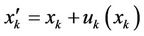 . The displacement fields are the solutions of the nonlinear partial differential equations in Equation (1), and these equations can be solved numerically using a multigrid method [2].
2.2. Landmark-Based Registration Using CSRBF Spline
CSRBF spline registration requires user intervention to establish the correspondences between the same object in both source and target images. The main steps in landmark based registration algorithm consist of identifying pairs of corresponding landmarks in images, computing the appropriate transformation parameters, and then interpolating transformation fields for positions not on the landmarks.
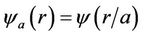
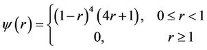
The properties of radial basis functions (RBFs) are well defined and have proven to be efficient for interpolation [23]. Researchers have proposed using many different RBFs for landmark-based image registration with or without compact support[13]. The main disadvantage of RBFs without compact support is that the resultant transformation acts as a global function so that a single landmark pair would affect entire image region, a typical example is thin-plate spline (TPS). The transformations generated by CSRBF are localized, and the impacts of landmarks on a certain location are inversely proportional to the distances to the landmarks. In our implementation, we selected the Wendland y function [23] as the RBF with the spatial-support parameter a for local registration:
 (2)
(2)
where
 (3)
(3)
This function is positively defined in a 3D space and has C2 continuity (second derivative continuity). An RBF is based on a scalar radius r and is symmetric around a control point. The smaller the value of a, the more local the confinement of for at the landmark control points. To handle large deformations using CSRBF spline registration, a large a value may be needed [13]. Therefore, selection of this a parameter must be a compromise between the requirement for local confinement and the existence of large deformations in certain clinical situations.
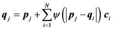
CSRBF spline registration initially identifies the corresponding coordinate locations (control points) in both source and target images. The control-point pairs are then used to determine a coordinate transformation (mapping) between two images. The set of control points in the source image can be denoted as , and the corresponding control-point set in the target image can be denoted as
 . A successful registration should map every point in
  to the corresponding
 . Transformation of the mapping function can be represented as a linear combination of the CSRBFs of the distance between two control-point sets:
 (4)
(4)
where i, j = 1, ···, N, and N is the number of control points. For a given set of control points, the transformation coefficients  are the solutions for this linear system:
 (5)
(5)
where  and
and .
.
Once the transformation coefficients  are obtained as depicted in Equation (5), the mapping between any points x other than the control points is given as follows:
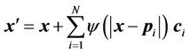 (6)
(6)
where x' is the corresponding point of x, and
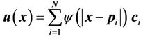
is the displacement field for point x. The displacement fields generally depend on both the number and spatial distribution of control points. For a given set of controlpoint pairs, the displacement fields depend on the value of the compact support parameter a. Usually, a small a value makes the transformation more local to the control points, and the deformation of the object is relatively small. In certain clinical situations, a large a value is required to handle large deformations in a small region. When a large a value is used, the CSRBF spline transformation may influence the outer regions away from the area defined by the control points.
2.3. Multi-Step Registration Using CSRBF Spline
With large deformations, landmark-based registration may produce “cross-over” of the grid, as shown in Figure 5(c). Although a large support size can be used for regions away from the region of interest may lead to unrealistic displacement fields such as that caused by bone deformation as shown in Figure 4 (c)-(d). Joshi and Miller [24] mathematically proved the existence of diffeomorphism in a set of landmark correspondences with large deformations and derived an iterative algorithm. However, we argue that strict diffeomorphism may be overconstrained in many situations. Moreover, as a clinical solution for adaptive radiation therapy, our goal is to avoid “cross-over” in deformation with an affordable computational cost rather than solve a strict topologypreserve map. Therefore, we implemented a heuristic divide-and-conquer procedure to handle large deformation across patient anatomy while maintaining the locality of the transformation.
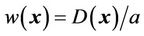
After selection of the control-point pairs, the distances between the corresponding points roughly represent the deformation of the subject from the source image to the target image. Using one-step registration would necessitate a large compact support parameter a for large deformation, which could violate the locality [13] of the transformation. In the present study, we implemented a multi-step CSRBF splines. We could artificially reduce the distances between the source and target control points by creating intermediate “virtual” control points between them as illustrated in Figure 1. The intermediate virtual control points are coordinates of points between source and target control points; they are not actual points identified in the images. The main reason for using these intermediate virtual control points is to reduce the distances between the source and intermediate points, making the transformation more local and topologically preserved when using Equation (4). At the end of this multi-step CSRBF registration process, the final control points are the same as the landmark points identified by the user.
The multi-step registration initially registers the source control points (real points) to the virtual control points

Figure 1. 2D representation of a multi-step CSRBF spline registration using two intermediate virtual control points (blue and yellow circles with crossed marks). The red open circles with the solid curve represent the source image, and the solid black dots are linked landmarks on the target image (dashed curve).
 , which are closest to the source control points. Next, the previous virtual control point set
  is used as the source set and registered to the next virtual control point set
 . This procedure is repeated until the final step, which registers the last set of virtual control points
  to the target control point set
 . The number of registration steps is n+1. In each step of the registration process, the same compact support parameter value a is used. The transformation coefficients
  are obtained for each step by repeatedly solving Equation (5), and these coefficients are used sequentially to calculate the displacement fields of every point using Equation (6) in the region of interest. The final displacement field between the source and target images is the cumulative displacement field obtained in the multiple steps.
2.4. The Hybrid Registration Algorithm
The image intensity-based deformable registration algorithm [2,9] works well for many clinical applications when the image quality is good and source and target images are relatively similar. The hybrid registration algorithm is designed for situations when the image quality and / or source and target similarity are inadequate for successful registration using the image intensity-based algorithm alone. Therefore, prior to the use of the hybrid registration, we first registered the image pair using intensity-based diffusion registration algorithm. We used the hybrid registration only when the diffusion registration could not produce satisfactory results.
As illustrated in the flowchart in Figure 2, the hybrid registration method includes four essential steps: 1) registering the entire region of interest using image intensity-based diffusion registration, 2) manually identifying control-point pairs in regions in which the previous registration results were considered inadequate, 3) using the multi-step CSRBF spline registration algorithm to register the local region of the image according to the predefined control-point pairs, and 4) combining the displacement fields from multi-step CSRBF spline registration with that those obtained from the diffusion registration.
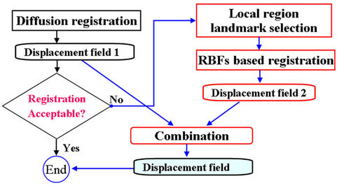
Figure 2. Diagram of the proposed hybrid deformable image registration approach.
The combination of two displacement fields should satisfy the smooth constraints for the two registration methods, and the local registration should not affect global registration of the entire region. In our implementation, we first used a spline function to connect all of the landmark points to calculate a closed 3D volume. We marked the interior of this 3D volume as the “in-field” volume, where the displacement field was determined solely using the CSRBF spline registration method. We then expanded the 3D surface of this in-field volume to create a “transition zone” with the width of the expansion equal to the compact support parameter a. Within the transition zone, the displacement field  was determined according to the weighted average of both of the displacement fields calculated using the intensity-based method
  and the landmark-based method
  at each position:
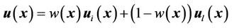 (7)
(7)
where the weighting function  can be determined using a linear function of Euclidean distance transformation
  [25,26] between the point of interest x and the 3D surface of the in-field volume:
 (8)
(8)
where the compact support parameter a normalizes the weighting function to a value within [0,1]. This is illustrated in the two-dimensional (2D) diagram in Figure 3. This implementation allows for CSRBF spline registration in the local region specified by the control points, whereas the image intensity-based diffusion registration controls the region away from the control points with a smooth transition in the transition zone.
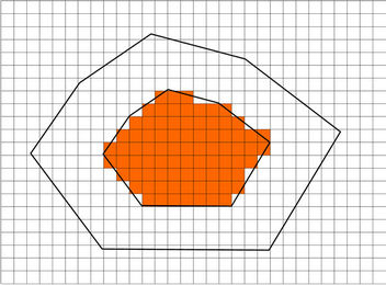
Figure 3. A 2D diagram showing the combination of landmark-based and image intensity-based registration. The peripheral landmark points form an in-field area (shaded) in which the displacement field was determined using the landmark-based registration method only. A transition zone is identified by expanding the in-field area using the registration parameter a. In the transition zone, the displacement field is computed based on the weighted average of the displacement fields with both methods. In the “out-field” area, the displacement field was determined solely using the intensity-based registration method.
2.5. Patient Data
Computed tomography (CT) images for four patients with prostate cancer, two patients with lung cancer, and one patient with head and neck cancer were used to test the accuracy and efficiency of the hybrid deformable image registration method. For the prostate cancer patients, daily (target) CT images were acquired using a CT-on-rails system (EXaCT; Varian Medical Systems, Palo Alto, CA). For the lung cancer patients, four-dimensional (4D) CT images were used to test the registration of tumor sliding along chest wall. The 4D CT data were reconstructed using CT scans acquired synchronously with the respiratory signals representing 3D CT data sets at various breathing phases (total, 10 phases). In 4D CT images, the 0% phase CT images (denoted by T0) and 50% phase CT images (denoted by T5), corresponding to the end of inspiration and expiration scans, respectively, and the largest range of tumor motion owing to respiration appears in the CT images in these two phases.
2.6. Validation Method
We used the results of the deformable image registration to determine whether this transformation can correctly auto-delineate the daily target volume. In this procedure the manually drawn contours in the source CT image were transformed to the contour in target CT image using the displacement field calculated from deformable image registration. The deformed contours in the target image automatically segmented the anatomic structures in the target image. Precise registration led to the deformed contours correctly fitting the corresponding structures in the target image. Therefore, the deformed contours facilitated evaluation of the image registration algorithm. The deformable image registration methods were implemented using the C++ programming language. All tests were run on an Intel Pentium IV (2.8 GHz)-equipped personal computer.
3. Results
3.1. Single-step vs Multi-Step CSRBF Spline Registration
In the multi-step CSRBF registration algorithm, the number of steps is specified by the user and depends mainly on the distances between source and target control points. Our experience showed that a four-step procedure is reasonable for challenging cases with very large deformations.
Figure 4 shows the differences in one-, two-, threeand four-step registration using an artificial cuboid in the prostate cancer CT images. We identified 18 controlpoint pairs on the edges of the rectangle denoting the cuboid in one particular slice. This figure demonstrates
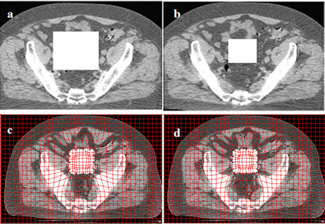
Figure 4. Deformed images using the one-step and multi-step CSRBF spline methods. (a) A large artificial square in the source image; (b) A small square in the target image; (c) Deformed image using the one-step method (a = 65, pelvic bones deformed); (d) Deformed image using the two-step method (a = 52); (e) Deformed image using the three-step method (a = 45); (f) Deformed image using the four-step method (a = 40).
that the four-step algorithm achieves the best locality of transformation, as it deforms the cuboid correctly while minimizing the influence on the surrounding tissues. In one-step registration, the algorithm can deform the cuboid as well as the pelvic bones. In this example, different a parameters are used for different registration approaches. Among these four approaches, the one-step approach requires a maximum a value, while the four-step approach uses the smallest one. This is consistent with a single control-point pair study performed by Fornefett et al. [13] They showed that to achieve a given displacement D, the minimum compact support parameter a should satisfy a > 3.66D for 3D cases. Although this relationship is not exactly applicable for multiple control points, it can serve as a guideline for tuning a parameter. In multi-step registration, because the displacement D is accumulatively achieved in a few steps and only a portion of it is achieved in each step, a smaller parameter a than that in the single-step algorithm can be used.
Figure 5 shows the displacement field obtained using one-step registration versus four-step registration with four landmark point pairs and the same compact support parameter a. The four-step registration produced more reasonable mapping of the transformation, whereas the one-step registration produced unrealistic mapping. Using
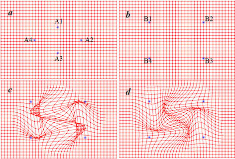
Figure 5. A 2D depiction of deformable registration using the one-step and multi-step CSRBF spline methods. (a) Four control points shown on the source image; (b) The corresponding matched control points shown on the target image. Points Ai match to Bi, in which i = 1, 2, 3, and 4; (c) The displacement field in the one-step method, which shows that the resultant displacement field does not have the desired one-to-one mapping; (d) The displacement field in the multi-step method, which is more reasonable than that in the one-step method.
the multi-step method allows for selection of as small a parameter a as possible to maintain the locality of the transformation.
Figure 6 shows transverse slices of the CSRBF spline registration results for a pair of CT images of a prostate tumor using the one-step and multi-step methods, respectively. To illustrate the differences in these two registration approaches, we selected an identical set of control points around the boundary of the prostate and rectum, which is shown in Figure 6(a) (on the source image) and Figure 6(b) (on the target image). The smallest compact parameter a used in the oneand four-step approaches was 130 and 32, respectively. The deformed images (Figures 6(c) and 6(d)) show that one-step CSRBF spline registration greatly influenced the region close to the area specified by the control points, whereas the four-step registration had produced more local transformation. The deformed contours also show that the multi-step CSRBF spline registration (Figure 6(f)) matched the anatomy better than the one-step method did (Figure 6(e)). The multi-step method handled a large deformation with good locality of transformation in this case. We achieved similar results with other prostate cancer cases.
3.2. Prostate Cancer Cases
The goal of deformable image registration in our study was to auto-delineate the anatomic structures by mapping the manual contours in the treatment planning CT image to the daily CT image. The deformed contours achieved using the three registration approaches (image intensity-based diffusion, landmark-based CSRBF spline, and
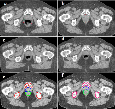
Figure 6. One-step CSRBFs spline registration versus multistep CSRBFs spline registration for CT images of prostate patient.Blue and green contours stand for prostate and rectum respectively. (a), (b) Control points were selected around the boundary of prostate and rectum; (c) Deformed image using 1-step method, a = 120; (d) Deformed image using 4-step method, a = 50; (e) Deformed contours using the 1-step CSRBFs spline registration; (f) Deformed contours using the 4-step CSRBFs spline registration. The contours are better matched in (f) than in (e), especially for the pelvis bones. The results show that the multi-step approach is more accurate in mapping contours for this case.
hybrid) are shown in Figure 7. The deformed contours achieved using only the diffusion registration (Figure 7(b)) did not correctly map the structures of the bladder or prostate owing to the low soft-tissue contrast between the two organs. The deformed contours achieved for the bladder and prostate using the multi-step CSRBF spline registration correctly mapped the structures of the bladder, prostate, and seminal vesicles, but the deformed contour of the rectum was not a good match for the anatomy (Figure 7(c)). The deformed contours resulted from a combination of the intensity diffusion and CSRBF spline approaches, thereby achieving good matches for these anatomical structures (Figure 7(d)). In this example, the registration error for the image intensity-based method resulted mainly from correspondence ambiguity arising from the low intensity contrast between the boundaries of the bladder and prostate. Applying CSRBF spline registration to this local ambiguous region reduced this registration error. We obtained similar results for the three other prostate cancer cases. The registration volume was 423 × 251 × 53 (voxels), and we used 13 control points. The CPU times were 136.0, 9.1, and 152.2 seconds for the diffusion, CSRBF, and our hybrid method, respectively.
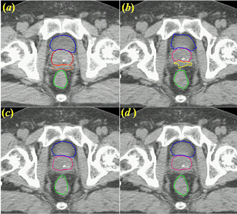
Figure 7. Contour mapping using a displacement field obtained with three deformable image registration approaches. (a) The original reference contours overlaid on the planning CT image, where Blue, red, orange and green contours stand for bladder, prostate, seminal vesicle and rectum, respectively; (b) Deformed contours created using diffusion-based deformable image registration alone; (c) Deformed contours created using CSRBF spline registration alone for the prostate and bladder only. Note that the deformed contours for the rectum were not accurate because the rectum was not used and was outside the region of compact support; (d) Deformed contours created using the hybrid registration method combining (b) and (c).
3.3. 4D CT of Lung Cancer Cases
In this experiment, we will demonstrate the application of our hybrid algorithm in handling the motion discontinuity along tissue interface. We used a lung cancer case with a 4D CT image data set in which lung tumors had large superior-inferior motion relative to the nearby, relatively stationary chest wall. We manually delineated the contours of the tumor and normal structures in the reference phase (T5). The peak-to-peak tumor movement from phase T5 to phase T0 was 2.5 cm. Although we were able to track the motion of structures using the image intensity-based diffusion registration method, the smoothing constraint achieved using this method prevented the tumor from sliding along the chest wall. This can be observed in the images shown in middle column in Figure 8, which show a “dragging effect” in the deformed contour (indicated by green contour) with use of the diffusion method alone. Owing to the smoothing requirement in these automatic image registration methods, the tissue cannot slide freely against a stationary check wall. However, using the CSRBF method, we were able to constraint the registration based on contours defined by human intervention. The result of the CSRBF correction with the hybrid method is shown in the right column of
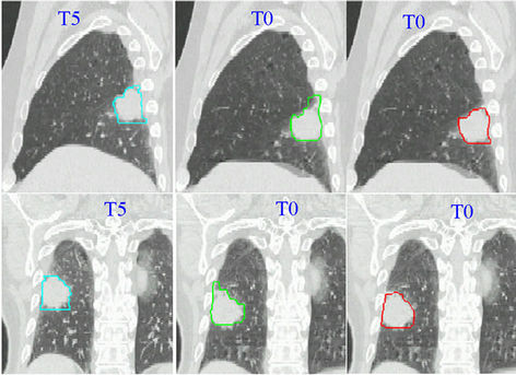
Figure 8. Auto-segmentation of a lung tumor using the diffusion and hybrid registration methods. The sagittal view is shown in the upper row, whereas the coronal view is shown in the bottom row. The left column contains the reference-phase CT scans (T5; end-of-expiration phase) with manual contours overlaid. The middle column images are T0 scans (end-of-inspiration phase) with contours deformed using the diffusion registration method. We observed a drag in the superior GTV, which attached to the chest wall. The images in the right column show the deformed contours created using the hybrid registration method. The deformed contour matches the GTV correctly.
Figure 8, indicating a good agreement with the reference tumor boundary (gross tumor volume [GTV]) in the left column of Figure 8. The registration volume in this case was 350 × 239 × 111 in voxels and we used 14 control points. The CPU times were 266.6 s for the diffusion method, 20.4 s for the CSRBF method, and 304.3 s for the hybrid method.
4. Discussion
In this study, we proposed the use of a hybrid deformable image registration approach that combines automatic image intensity-based deformable image registration with a local deformation registration method using a compact support spline. We also implemented a multi-step CSRBF registration method that improved the handling of large deformations while preserving the locality of transformation. Our results have demonstrated that the hybrid method improved the effectiveness of deformable image registration in handling many of the challenging clinical applications with moderated human intervention. In our cases, identification of these pairs in source and target images using our in-house software program took about 5 to 10 minutes.
For landmark-based registration, a basic assumption is that a set of corresponding landmarks can be established across the source and target image. Landmarks can be points, lines, surfaces, or volumes; in this investigation, however, we only considered point-based landmarks in this study. These corresponding points are often considered to be control points, and the goal of the registration process is to find a transformation between two images using the information from the corresponding landmarks [24,27]. Bookstein [28] proposed a landmark-based approach to nonrigid image registration that used TPS interpolation. Rohr et al. [29] further developed this technique and incorporated the elastic constraints and orientations information into landmark-based registration [30]. The TPS algorithm is also a general RBF-based spline algorithm [13,31,32]. In TPS registration, each control point has a global influence on the transformation, and dealing with local deformations, which is important as demonstrated in our study, is difficult. Many investigators have proposed using CSRBF splines for deformable image registration [13,31,32], which can handle local as well as global deformation issues. Very recently, investigators proposed using a Gaussian elastic body spline (GEBS) deformable-image registration algorithm [33,34]. The GEBS algorithm also can handle local as well as global deformations via a compact support parameter similar to that in CSRBF splines. Furthermore, researchers considered the CSRBF spline algorithm to be more computationally efficient than the GEBS algorithm [34].
The image intensity-based deformable registration algorithms have gained popularity in medical imaging applications [2,3,8-10,21]. Diffusion registrations are a constrained optimization method, and the optimal solution can be achieved by the optimization of an image similarity measure. The advantages of diffusion registration over landmark based registration methods are that it is fully automatic. The implicit assumption as a result is that the correspondences can be determined by image features in both source and target image images. However, similarity measures may not be reliable if the inherent image contrast and / or intensity levels are insufficient or nonexistent, or inaccurate (due to image artifacts) and thus unable to identify the same object in both images [12]. For practical reasons, human intervention is necessary to constraint registration in the areas of interest. This was the main reason we devised the hybrid registration approach for clinical applications.
Our results showed that our proposed hybrid registration approach is applicable to a variety of typical image-guided radiotherapy situations, such as low-contrast images of the prostate, dental imaging artifacts, and the sliding tumor problem in lung cancer cases described above. As discussed in section 2.2, the registration result depends on the number and spatial distribution of control points. To achieve accurate registration, defining the control-point pairs near the boundaries of target structures is crucial. Landmark-based registration can become computationally expensive if the number of control points increases. The proposed hybrid registration approach provides a convenient compromise for reducing the requirement of a large number of control points by using global, automatic intensity-based registration.
5. Conclusion
In this study, we investigated our proposed hybrid deformable image registration approach that combines multi-step CSRBF spline registration of local image regions with global intensity based registration. We demonstrated that this hybrid algorithm could improve the registration results with minimal human intervention. In this approach, we used the landmark-based CSRBF spline algorithm to adjust the local deformations. We also implemented a multi-step strategy to improve the ability of the CSRBF algorithm to handle large deformations while preserving the locality of the transformation. Our proposed hybrid approach improves the robustness and practicality of deformable image registration for image-guided clinical applications.
6. Acknowledgements
The authors would like to thank Mr. Donald Norwood from department of scientific publishing for editing this manuscript.
REFERENCES
- A. Bharatha, M. Hirose, N. Hata, et al., “Evaluation of Three-Dimensional Finite Element-Based Deformable Registration of Preand Intraoperative Prostate Imaging,” Medical Physics, Vol. 28, No. 2, 2001, pp. 2551-2560. doi:10.1118/1.1414009
- S. Gao, L. F. Zhang, H. Wang, et al., “A Deformable Image Registration Method to Handle Distended Rectums in Prostate Cancer Radiotherapy,” Medical Physics, Vol. 33, No. 9, 2006, pp. 3304-3312. doi:10.1118/1.2222077
- W. Lu, M. L. Chen, G. H. Olivera, K. J. Ruchala and T. R. Mackie, “Fast Free-Form Deformable Registration via Calculus of Variations,” Physics in Medicine and Biology, Vol. 49, No. 14, 2004, pp. 3067-3087. doi:10.1088/0031-9155/49/14/003
- T. R. Mackie, J. Kapatoes, K. Ruchala, et al., “Image Guidance for Precise Conformal Radiotherapy,” International Journal of Radiation Oncology, Biology and Physics, Vol. 56, No. 1, 2003, pp. 89-105. doi:10.1016/S0360-3016(03)00090-7
- E. Rietzel, G. T. Y. Chen, N. C. Choi and C. G. Willet, “Four-Dimensional Image-Based Treatment Planning: Target Volume Segmentation and Dose Calculation in the Presence of Respiratory Motion,” International Journal of Radiation Oncology, Biology and Physics, Vol. 61, No. 5, 2005, pp. 1535-1550. doi:10.1016/j.ijrobp.2004.11.037
- D. Sarrut, V. Boldea, S. Miguet and C. Ginestet, “Simulation of Four-Dimensional CT Images from Deformable Registration between Inhale and Exhale Breath-Hold CT Scans,” Medical Physics, Vol. 33, No. 3, 2006, pp. 605- 617. doi:10.1118/1.2161409
- E. Schreibmann, G. T. Y. Chen and L. Xing, “Image Interpolation in 4D CT Using a BSpline Deformable Registration Model,” International Journal of Radiation Oncology, Biology and Physics, Vol. 64, No. 5, 2006, pp. 1537-1550. doi:10.1016/j.ijrobp.2005.11.018
- H. Wang, L. Dong, M. F. Lii, et al., “Implementation and Validation of a Three-Dimensional Deformable Registration Algorithm for Targeted Prostate Cancer Radiotherapy,” International Journal of Radiation Oncology, Biology and Physics, Vol. 61, No. 3, 2005, pp. 725-735.
- H. Wang, L. Dong, J. O’Daniel, et al., “Validation of an Accelerated ‘Demons’ Algorithm for Deformable Image Registration in Radiation Therapy,” Physics in Medicine and Biology, Vol. 50, No. 12, 2005, pp. 2887-2905. doi:10.1088/0031-9155/50/12/011
- D. L. G. Hill, P. G. Batchelor, M. Holden and D. J. Hawkes, “Medical Image Registration,” Physics in Medicine and Biology, Vol. 46, No. 3, 2001, pp. R1-R45. doi:10.1088/0031-9155/46/3/201
- K. Rohr, “Landmark-Based Image Analysis: Using Geometric and Intensity Models,” Kluwer Academic Publisher, Dordrecht, 2001.
- W. R. Crum, L. D. Griffin, D. L. Hill and D. J. Hawkes, Zen and the Art of Medical Image Registration: Correspondence, Homology, and Quality,” NeuroImage, Vol. 20, No. 3, 2003, pp. 1425-1437. doi:10.1016/j.neuroimage.2003.07.014
- M. Fornefett, K. Rohr and H. S. Stiehl, “Radial Basis Functions with Compact Support for Elastic Registration of Medical Images,” Image and Vision Computing, Vol. 19, No. 1-2, 2001, pp. 87-96. doi:10.1016/S0262-8856(00)00057-3
- A. Azar, C. Y. Xu, X. Pennec and N. Ayache, “An Interactive Hybrid Non-Rigid Registration Framework for 3D Medical Images,” 3rd IEEE International Symposium on Biomedical Imaging: Nano to Macro, 2006, pp. 824-827.
- T. Hartkens, D. L. G. Hill, A. D. Castellano-Smith, et al., “Using Points and Surfaces to Improve Voxel-Based Non-Rigid Registration,” Proceedings of the 5th International Conference on Medical Image Computing and Computer-Assisted Intervention-Part II, 2002, pp. 565- 572.
- H. J. Johnson and G. E. Christensen, “Consistent Landmark and Intensity-Based Image Registration,” IEEE Transactions on Medical Imaging, Vol. 21, No. 5, 2002, pp. 450-461. doi:10.1109/TMI.2002.1009381
- E. Haber and J. Modersitzki, “Numerical Methods for Image Registration,” Oxford University Press, Oxford, 2004.
- P. Cachier, J.-F. Mangin, X. Pennec, et al., “Multisubject Non-Rigid Registration of Brain MRI Using Intensity and Geometric Features,” Medical Image Computing and Computer-Assisted Intervention, Vol. 2208, 2001, pp. 734-742.
- G. E. Christensen, R. D. Rabbitt and M. I. Miller, “Deformable Templates Using Large Deformation Kinematics,” IEEE Transactions on Image Processing, Vol. 5, No. 10, 1996, pp. 1435-1447. doi:10.1109/83.536892
- E. D’Agostino, F. Maes, D. Vandermeulen and P. Suetens, “A Viscous Fluid Model for Multimodal Non-Rigid Image Registration Using Mutual Information,” Medical Image Analysis, Vol. 7, No. 4, 2003, pp. 565-575. doi:10.1016/S1361-8415(03)00039-2
- M. Foskey, B. Davis, L. Goyal, et al., “Large Deformation 3D Image Registration in Image-Guided Radiation Therapy,” Physics in Medicine and Biology, Vol. 50, No. 24, 2005, pp. 5869-5892. doi:10.1088/0031-9155/50/24/008
- J.-P. Thirion, “Image Matching as a Diffusion Process: An Analogy with Maxwell’s Demons,” Medical Image Analysis, Vol. 2, No. 3, 1998, pp. 243-260. doi:10.1016/S1361-8415(98)80022-4
- H. Wendland, “Piecewise Polynomial, Positive Definite and Compactly Supported Radial Functions of Minimal Degree,” Advances in Computational Mathematics, Vol. 4, No. 1, 1995, pp. 389-396. doi:10.1007/BF02123482
- S. C. Joshi and M. I. Miller, “Landmark Matching via Large Deformation Diffeomorphisms,” IEEE Transactions on Image Processing, Vol. 9, No. 8, 2000, pp. 1357- 1370. doi:10.1109/83.855431
- G. Borgefors, “On Digital Distance Transforms in Three Dimensions,” Computer Vision and Image Understanding, Vol. 64, No. 3, 1996, pp. 368-376. doi:10.1006/cviu.1996.0065
- A. Rosenfeld and J. L. Pfaltz, “Distance Functions in Digital Pictures,” Pattern Recognition, Vol. 1, No. 1, 1968, pp. 33-61. doi:10.1016/0031-3203(68)90013-7
- J. V. Hajnal, D. J. Hawkes and D. L. G. Hill, Eds., “Medical Image Registration,” CRC Press, Boca Raton, 2001.
- F. L. Bookstein, “Principal Warps: Thin-Plate Splines and the Decomposition of Deformations,” IEEE Transactions on Pattern Analysis Machine Intelligence, Vol. 11, No. 6, 1989, pp. 567-585. doi:10.1109/34.24792
- K. Rohr, H. S. Stiehl, R. Sprengel, T. M. Buzug, J. Weese and M. H. Kuhn, “Landmark-Based Elastic Registration Using Approximating Thin-Plate Splines,” IEEE Transactions on Medical Imaging, Vol. 20, No. 6, 2001, pp. 526-534. doi:10.1109/42.929618
- K. Rohr, M. Fornefett and H. S. Stiehl, “Spline-Based Elastic Image Registration: Integration of Landmark Errors and Orientation Attributes,” Computer Vision & Image Understanding, Vol. 90, No. 2, 2003, pp. 153-168. doi:10.1016/S1077-3142(03)00048-1
- N. Arad, N. Dyn, D. Reisfeld and Y. Yeshurun, “Image Warping by Radial Basis Functions: Applications to Facial Expressions,” CVGIP: Graphical Models and Image Processing, Vol. 56, No. 2, 1994, pp. 161-172. doi:10.1006/cgip.1994.1015
- M. P. Wachowiak, X. G. Wang, A. Fenster and T. M. Peters, “Compact Support Radial Basis Functions for Soft Tissue Deformation,” Proceedings of the 2004 IEEE International Symposium on Biomedical Imaging: From Nano to Macro, Arlington, 15-18 April 2004, pp. 1259- 1262.
- J. Kohlrausch, K. Rohr and H. S. Stiehl, “A New Class of Elastic Body Splines for Nonrigid Registration of Medical Images,” Journal of Mathematical Imaging and Vision, Vol. 23, No. 3, 2005, pp. 253-280. doi:10.1007/s10851-005-0483-7
- V. Pekar, E. Gladilin and K. Rohr, “An Adaptive Irregular Grid Approach for 3D Deformable Image Registration,” Physics in Medicine and Biology, Vol. 51, No. 2, 2006, pp. 361-377. doi:10.1088/0031-9155/51/2/012