Advances in Nanoparticles
Vol.2 No.1(2013), Article ID:27885,7 pages DOI:10.4236/anp.2013.21005
Modified Bow-Tie Nanoparticles Operating in the Visible and Near Infrared Frequency Regime
Department of Applied Electronics, “Roma Tre” University, Rome, Italy
Email: renato.iovine@uniroma3.it, luigi.laspada@uniroma3.it, vegni@uniroma3.it
Received December 7, 2012; revised January 10, 2013; accepted January 20, 2013
Keywords: Bow-Tie; Nanoparticles; Localized Surface Plasmon Resonance; Analytical Models; Biomedical Applications
ABSTRACT
In this contribution electromagnetic properties of traditional and modified bow-tie nanoparticles are investigated. The modified bow-tie particles consist of a pair of opposing metallic truncated triangles, embedded in a dielectric environment, with a rectangular dielectric hole engraved on the metallic structure. New analytical models for both structures are developed in order to describe the nanoparticles electromagnetic behavior in terms of resonant wavelength position, magnitude and amplitude width for the extinction cross-section. Analytical results are compared to the numerical values and to the experimental ones existing in literature. Good agreement among them is obtained. Then, the structures are analyzed in terms of sensitivity properties. Results reveal that the modified bow-tie structure can be applied for biomedical applications.
1. Introduction
In the last few years several researchers have been involved in nanoparticle-based devices development, paving the way for new biomedical applications.
Metallic nanoparticles exhibit unusual optical properties deriving from the strong local electromagnetic field enhancement in the neighborhood of the structure under the Localized Surface Plasmon Resonance (LSPR) excitation [1].
As a result the interaction between the localized electromagnetic field and the surrounding dielectric environment is restricted in a small area. Therefore, such structures are very sensitive to changes in the refractive index of the surrounding dielectric medium.
Most of biomedical applications, based on nanoparticles, exploit the interaction between the electromagnetic field with metal nanoparticles in the Visible (VIS) and Near Infrared Region (NIR) [2]. These electromagnetic properties make metallic nanoparticles suitable for several application fields: such as biochemical sensing and detection [3,4], protein analysis [5,6], cell membrane function [7], food quality analysis [8]. They can also be used as contrast agents in cellular and biological imaging [9, 10], Raman signal intensity enhancement [11,12] and therapeutic applications as photo thermal destruction of cancerous cells [13].
The nanoparticle effectiveness as sensing or therapeutic tool depends on its optical properties. In particular, it is well known that smaller particles are excellent absorbers; and on the contrary the bigger ones are very strong scatters [14].
Although several researches have focalized the attention on the experimental evaluation of nanoparticle electromagnetic characteristics (in terms of wavelength position, magnitude and bandwidth), little is known about the possibility to control the physical phenomenon. Predicting the electromagnetic behavior of such structures is of considerable interest to build up inclusions that satisfy certain requirements, for specific applications.
In this regard, this paper attempts to present a new design method for bow-tie-based nanoparticles.
These particles (a pair of opposing gold truncated triangles) are used in order to obtain the strong hot spot in their gap. In fact, the possibility to tune the structure response by varying its geometrical parameters such as bow-tie angle, side length and gap distance has been studied [15,16]. The effects of the bow-tie geometry on its sensitivity have been recently evaluated [17]. Such results suggest that bow-tie nanoparticles can be employed for sensing applications. Despite this, the literature is almost silent on the development of models useful to design such structures.
For this reason, in this paper new analytical models are presented.
Moreover, in this study we propose modified bow-tie particles by using a dielectric rectangular hole engraved on the structure. In this configuration nanoparticles exhibit a multi resonant behavior associated with a high electric field localizations (hot spots) near the nanoparticles.
The main advantage in using analytical models is the possibility to tune the nanostructure resonances, in the VIS and NIR frequency regime, by changing its geometrical and electromagnetic properties.
The article is structured as follows:
• First of all, the electromagnetic properties of a classical bow-tie nanoparticle are evaluated in terms of extinction cross-section. A new analytical model, describing its electromagnetic resonant behaviour in terms of wavelength position, magnitude and bandwidth, is proposed. In order to validate the proposed closed-form formula, a comparison among analytical, numerical and experimental values is shown.
• Secondly, by introducing a dielectric hole in the bowtie particle, an additional hot spot and a multi resonant behavior were obtained. The effect of the dielectric hole, on the particle electromagnetic behavior, is analytically described.
• Then, the effects of geometrical and electromagnetic parameters on the resonant properties for both structures are explored.
• Finally, the sensitivity of the traditional and modified bow-tie particles are evaluated and discussed. A comparison between the sensitivity of the traditional bowtie and the modified one is proposed.
2. Analytical Models and Electromagnetic Properties of Bow-Tie Nanoparticles
In this section, the electromagnetic properties for the classical bow-tie geometry and the modified one are presented. The aim is to present a new design method to build up the aforementioned nanoparticles with desired electromagnetic properties.
The proposed geometries consist of a pair of opposing metallic truncated triangles embedded in a dielectric environment. The structure is excited by a plane-wave, having the electric field  parallel and the propagation vector
 ![]() perpendicular to the plane containing the particle as depicted in Figure 1. Specifically, the nanostructure optical properties in terms of extinction cross-sections (Cext) and the electric field distribution (hot spots) at the resonant wavelength are evaluated.
perpendicular to the plane containing the particle as depicted in Figure 1. Specifically, the nanostructure optical properties in terms of extinction cross-sections (Cext) and the electric field distribution (hot spots) at the resonant wavelength are evaluated.
The considered geometrical parameters are shown in Figure 1. They are: the major-side length a, the height of the triangles b, the minor-side length c, the inter-particles gap d, the height of the dielectric hole g, the minor-side of the dielectric hole f and the thickness e of the structures.
In order to study their resonant properties the following assumptions are stated:
• The particle sizes are much smaller than the operative wavelength [18]. In this way, inclusions can be considered “electrically small”. Therefore their resonant behavior can be studied in terms of quasi-static approximation;
• The particle is homogeneous and the surrounding dielectric environment is a homogeneous and nonabsorbing medium.
Under such conditions, we can relate the electromagnetic extinction properties of the nanoparticle to its polarizability expression.
Let’s point out some relevant aspects concerning the present work:
• For metallic nanoparticles, experimental values [19] of the complex permittivity function have been used;
• The surrounding dielectric medium is considered to be vacuum.
2.1. Bow-Tie Analytical Model and Electromagnetic Properties
In case of arbitrary shaped particles, the dipolar polarizability expression reads [18]:
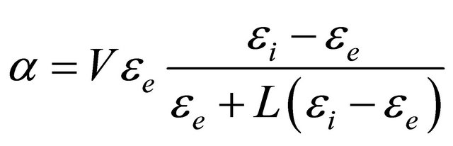 (1)
(1)
where V is the particle volume, εe is the electric permittivity of the surrounding dielectric environment, εi is the inclusion electric permittivity and L is the depolarization factor. Following the same procedure conducted in [20], it is possible to develop new analytical models describing the extinction cross-section properties for both considered nanoparticles. The general corresponding expression can be written as follows:
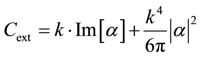 (2)
(2)
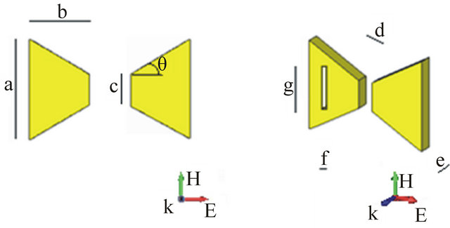
Figure 1. Geometrical sketch of the particles under study: (a) Top view of classical bow-tie particle; (b) Perspective view of modified bow-tie particle by dielectric incision. Geometrical parameters: a = 2btanθ + c; b = 100 nm; c = 50 nm; d = 20 nm; e = 25 nm; 10 ≤ f ≤ 30; 80 ≤ g ≤ 100; 30˚ ≤ θ ≤ 60˚.
where  is the wave number, λ is the wavelength and
  is the refractive index of the surrounding dielectric environment.
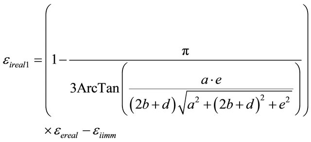
Considering such elements and the electric field polarization of the impinging plane wave, the polarizability formula for the classical bow-tie particle follows:
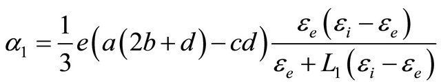 (3)
(3)
with
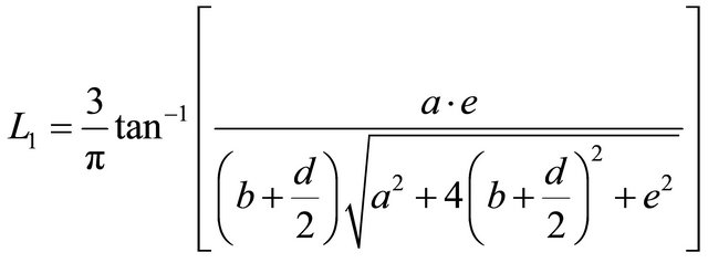 (4)
(4)
In Figure 2 a comparison between analytical model and numerical simulation, performed by the full-wave solver CST Microwave studio [21], for the extinction cross-section spectra of gold traditional bow-tie nanoparticle is shown.
In our simulations we have used a time-domain method based on finite integration technique (FIT). In particular, the structure is discretized using hexagonal mesh. To make sure that the particles are represented as well as possible, we have optimized the Global Mesh Properties parameters (lines per wavelength: 30; lower mesh limit: 30; mesh line ratio limit: 10) and used a Mesh refinement process (local edge refinement factor: 6; local volume refinement factor: 4). The final mesh consisted of around 2,000,000 mesh elements depending on the geometrical parameters.
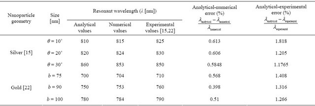
In order to verify the quality of the proposed model, analytical results are compared to the numerical values and to the experimental ones [15,22], for different geometrical parameter dimensions, as reported in Table 1.
The relative errors were evaluated and reported in Table 1. Good agreement among all the three results was achieved.
2.2. Modified Bow-Tie Analytical Model and Multi-Resonant Properties
Until now inclusions have been assumed to be homogeneous structures.
In this section a new non homogeneous structure is proposed. The classical bow-tie structure is modified by inserting a dielectric hole in one of its side, as shown in Figure 1(b).
The reason for the employment of the dielectric hole in the classical bow-tie particle is the possibility to excite a new resonant frequency on the same structure in order to achieve a multi-band behavior.
The main advantages to use a multi-resonant structure are the following:
• Improved sensor sensitivity: the excitation of multiple resonant frequencies in the same structure, caused by such a configuration, leads to a high electromagnetic field localization in the neighbourhood of the nanoparticles (an additional hot spot is obtained). By using the dielectric hole (perpendicular to the electric field oscillation axis) inside the bow-tie particle, an additional resonant peak is obtained as shown in Figure 3. From a physical point of view, the multi-resonant behavior can be related to the additional capacitance existing inside the particle. This resonance is localized towards longer wavelengths compared to the classical bow-tie configuration (Figure 3) due to the fact that we have assumed g > c as shown in Figure 1.
• The possibility to tune the nanostructure resonances, by changing its geometrical and electromagnetic characteristics in order to coincide with the spectral absorption characteristics of the sample is under study. It turns out to be a useful tool for absorption measurements.
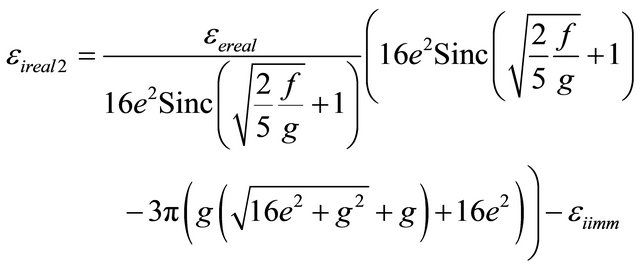
In particular, by following the same procedure conducted in the previous section, in order to control and to tune such frequencies a new analytical model for the
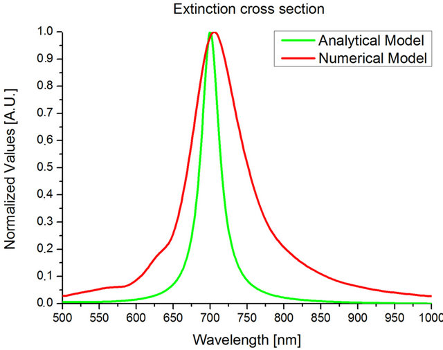
Figure 2. Analytical-numerical model comparison for the extinction cross-section spectra for gold classical bow-tie nanoparticle: θ = 30˚.
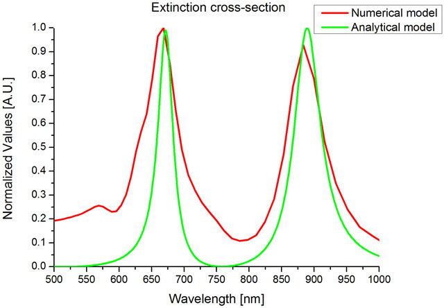
Figure 3. Analytical-numerical model comparison for the extinction cross-section spectra for gold modified bow-tie nanoparticles: f = 10 nm, g = 80 nm and θ = 30˚.
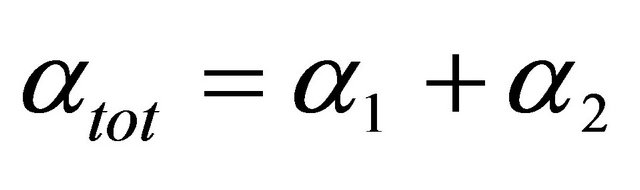
modified bow-tie polarizability was developed. In this case the total polarizability is the sum of the traditional bow-tie polarizability α1 and the dielectric hole polarizability α2 as follows
 (5)
(5)
being:
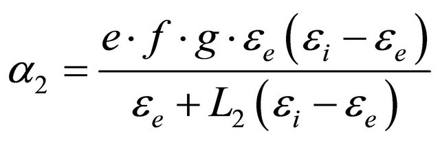 (6)
(6)
with
 (7)
(7)
A comparison between analytical and numerical models for the extinction cross-section spectra is shown in Figure 3.
This electromagnetic behavior is also confirmed by full-wave numerical simulations. Considering a modified bow-tie with the following geometrical parameters for the dielectric hole: f = 10 nm and g = 80 nm the electric field distribution in the nanoparticle is shown in Figures 4 and 5. It can be noted that the electric field localization inside the dielectric hole (Figure 4) leads to a new resonant peak (883 nm), while the electric field distribution existing in the gap (Figure 5) represents the resonant frequency (668 nm) that can be found in the classical bow-tie configuration.
3. Effect of the Geometrical and Electromagnetic Parameters
The inclusion electromagnetic properties are highly dependent on the size, shape, and nanoparticle composition. Therefore, in this section the effect of the geometrical and electromagnetic parameters on the nanoparticle resonant behavior is studied. In order to design the aforementioned inclusions, we relate their electromagnetic resonant properties to the geometrical parameters, to the metallic material properties (real and imaginary part of permittivity: εreal and εimm, respectively), and to the surrounding dielectric environment permittivity εe. It is well known that the particle polarizability is at its resonant condition when:
![]() (8)
(8)
Assuming that the inclusion permittivity can be expressed as εi = εireal + jεiimm and the background material permittivity as εe = εereal + jεeimm the particle resonant condition (in the quasi-static approximation) occurs at:
 (9)
(9)
Figure 4. Near electric field distribution of modified bow-tie particle with θ = 30˚; f = 10 nm, g = 80 nm at 883 nm.
Figure 5. Near electric field distribution of modified bow-tie particle with θ = 30˚; f = 10 nm, g = 80 nm at 668 nm.
Then the role of the geometrical parameters, on the bow-tie particle resonant behavior can be evaluated. By using (9) and assuming a background lossless material (εeimm = 0) the traditional bow-tie particle resonant condition reads:
(10)
An example of the effects of the geometrical parameters variations on bow-tie resonant properties is shown in Figure 6.
Let’s now consider the modified bow-tie particle. A similar expression for the resonant condition can be obtained. In this case we have two coexisting solutions. The first resonant condition was reported before and it refers to the traditional bow-tie resonance-see (10). The second
Table 1. Comparison of resonant wavelengths for classical bow-tie particle: analytical, numerical and experimental values (silver [15]: a = 2btan[θ] + c, b = 140 nm, c = 5 nm, d = 28.5 nm, e = 48 nm; gold [22]: a = 2btan[θ] + c, c = 5 nm, d = 12 nm, e = 20 nm, θ = 28˚).
resonant condition (corresponding to the dielectric hole resonant behavior) reads:
 (11)
(11)
By varying the geometrical parameters of the dielectric hole it is possible to tune the position, magnitude and amplitude width of the additional resonant peak as shown in Figures 7 and 8.
4. Sensitivity Analysis and Performances
In this section we analyze the sensitivity properties of both bow-tie nanoparticles. The sensitivity is commonly defined as the ratio wavelength shift to refractive index variation, expressed in nm/RIU (Refractive Index Unit). The sensitivity performances in the range 1 < n < 1.6 for different geometrical parameters of the traditional bowtie and the modified one have been evaluated (Tables 2 and 3).
In particular, in Table 2 a comparison for the traditional bow-tie among analytical, numerical and experimental values [23,24] is reported.
Instead, in Table 3 the sensitivity performances for the modified bow-tie particle, as a function of f and g values, are shown.
The following relevant aspects can be pointed out:
First of all, the introduction of the dielectric hole leads to higher sensitivities values compared to the traditional configuration for the first resonant peak (compared to the traditional bow-tie particle).
Secondly, the sensitivity of the first LSPR peak (■) is small influenced by varying the geometrical parameters
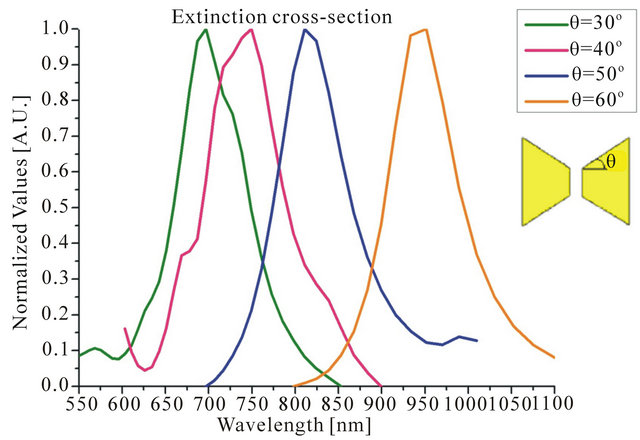
Figure 6. Extinction spectra of classical bow-tie particles by varying θ.
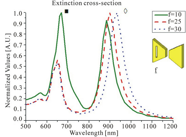
Figure 7. Extinction spectra of modified bow-tie particle by varying dielectric incision geometry: 10 nm < f < 30 nm, θ = 30˚, g = 80 nm.
of the dielectric hole. On the other hand, the new resonant peak (◊), related to the hole, is strongly influenced by such variations. In particular it is possible to observe
Table 2. Sensitivity values for traditional bow-tie particles.
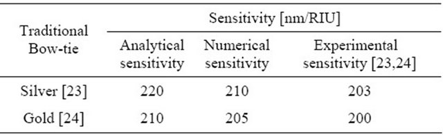
Table 3. Sensitivity performances of modified bow-tie particles for different value of f and g.
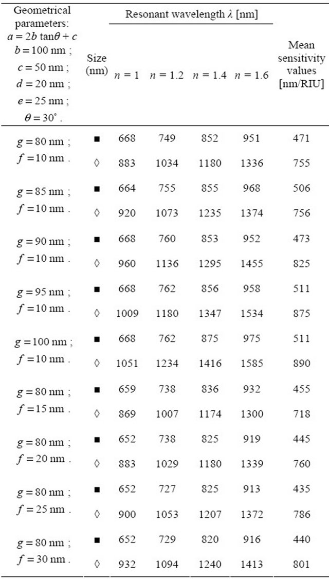
that sensitivity performances grow by increasing the hole length g.
The following bow-tie configuration: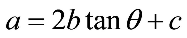 ;
;
b = 100 nm; c = 50 nm; d = 20 nm; e = 25 nm; θ = 30˚; g = 100 nm; f = 10 nm exhibits good value of sensitivity for the LSPR peaks (■ 511 nm/RIU and ◊ 890 nm/RIU). Such a result is confirmed by the analytical model and numerical simulations, suggesting the possibility to use the modified bow-tie structure for sensing applications.
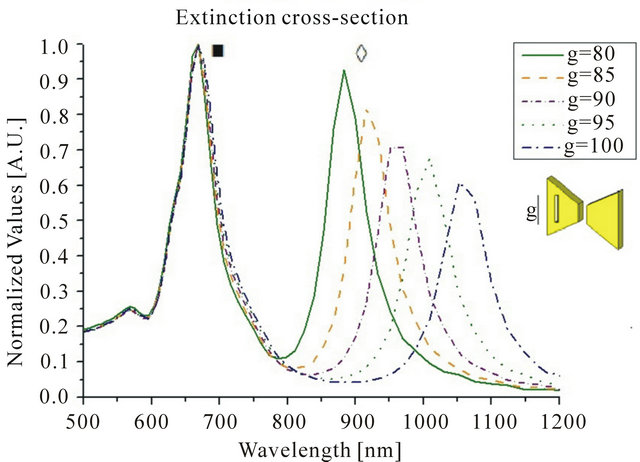
Figure 8. Extinction spectra of modified bow-tie particle by varying dielectric incision geometry: 80 nm < g < 100 nm, θ = 30˚, f = 10 nm.
5. Conclusions
In this contribution electromagnetic properties of traditional and modified bow-tie particles in the Infrared and Visible frequency range were investigated.
New closed-form analytical models for both kinds of structures were proposed, in order to describe their resonant extinction cross-section behavior in terms of wavelength position, magnitude and bandwidth.
Good agreement among analytical models, numerical results and experimental values existing in literature was achieved.
By using the proposed models, the effects of the geometrical and electromagnetic parameters on the nanoparticles resonant properties were studied.
Finally, the structures were analyzed in terms of sensitivity properties, in order to verify the possibility to use them as sensing platform in the visible and infrared frequency regime for biomedical applications.
In particular, analytical, numerical and experimental results clearly demonstrated and confirmed the high sensitivity properties of the proposed modified bow-tie particles.
REFERENCES
- A. Moores and F. Goettmann, “The Plasmon Band in Noble Metal Nanoparticles: An Introduction to Theory and Applications,” New Journal of Chemistry, Vol. 30, No. 8, 2006, pp. 1121-1132. doi:10.1039/b604038c
- W. Cai, T. Gao, H. Hong and J. Sun, “Applications of Gold Nanoparticles in Cancer Nanotechnology,” Nanotechnology, Science and Applications, Vol. 1, 2008, pp. 17-32.
- J. C. Riboh, A. J. Haes, A. D. McFarland, C. Ranjit and R. P. Van Duyne, “A Nanoscale Optical Biosensor: Real Time Immunoassay and Nanoparticle Adhesion,” The Journal of Physical Chemistry B, Vol. 107, No. 8, 2003, pp. 1772- 1780. doi:10.1021/jp022130v
- J. J. Storhoff, R. Elghanian, R. C. Mucic, C. A. Mirkin and R. L. Letsinger, “DNA Directed Synthesis of Binary Nanoparticle Network Materials,” Journal of American Chemical Society, Vol. 120, No. 48, 1998, pp. 12674- 12675. doi:10.1021/ja982721s
- E. M. Larsson, J. Alegret, M. Kall and D. S. Sutherland, “Sensing Characteristics of NIR localized Surface Plasmon Resonances in Gold Nanoring for Application as Ultrasensitive Biosensors,” Nano Letters, Vol. 5, No. 5, 2007, pp. 1256-1263. doi:10.1021/nl0701612
- R. Bukasov, T. A. Ali, P. Nordlander and J. S. ShumakerParry, “Probing the Plasmonic Near-Field of Gold Nanocrescent Antennas,” ACS Nano, Vol. 4, No. 11, 2010, pp. 6639-6650. doi:10.1021/nn101994t
- W. J. Galush, S. A. Shelby, M. J. Mulvihill, A. Tao, P. Yang and J. T. Groves, “A Nanocube Plasmonic Sensor for Molecular Binding on Membrane Surfaces,” Nano Letters, Vol. 9, No. 5, 2009, pp. 2077-2082. doi:10.1021/nl900513k
- H. M. Hiep, T. Endo, K. Kerman, M. Chikae, D.-K. Kim, S. Yamamura, Y. Takamura and E. Tamiya, “A Localized Surface Plasmon Resonance Based Immunosensor for the Detection of Casein in Milk,” Science and Technology of Advanced Materials, Vol. 8, No. 4, 2007, pp. 331-338. doi:10.1016/j.stam.2006.12.010
- D. Yelin, D. Oron, S. Thiberge, E. Moses, Y. Silberberg and I. Willner, “Multiphoton Plasmon-Resonance Microscopy,” Optics Express, Vol. 11, No. 12, 2003, pp. 1385- 1391. doi:10.1364/OE.11.001385
- K. Sokolov, M. Follen, J. Aaron, I. Pavlova, A. Malpica, R. Lotan and R. Richards-Kortum, “Real-Time Vital Optical Imaging of Precancer Using Anti-Epidermal Growth Factor Receptor Antibodies Conjugated to Gold Nanoparticles,” Cancer Research, Vol. 63, No. 9, 2003, pp. 1999- 2004.
- M. Y. Sham, H. Xu and R. Cromer, “SERS Nanoparticles: a New Optical Detection Modality for Cancer Diagnosis,” Nanomedicine, Vol. 2, No. 5, 2007, pp. 725-734. doi:10.2217/17435889.2.5.725
- L. Sun, C. Yu and J. Irudayaraj, “Raman Multiplexers for Alternative Gene Splicing,” Analytical Chemistry, Vol. 80, No. 9, 2008, pp. 3342-3349. doi:10.1021/ac702542n
- X. Huang, P. K. Jain, I. H. El-Sayed and M. A. El-Sayed, “Plasmonic Photothermal Therapy (PPTT) Using Gold Nanoparticles,” Lasers in Medical Science, Vol. 23, No. 3, 2008, pp. 217-228. doi:10.1007/s10103-007-0470-x
- P. K. Jain, K. S. Lee, I. H. El-Sayed and M. A. El-Sayed, “Calculated Absorption and Scattering Properties of Gold Nanoparticles of Different Size, Shape, and Composition: Applications in Biological Imaging and Biomedicine,” Journal of Physical Chemistry B, Vol. 110, No. 14, 2006, pp. 7238-7248. doi:10.1021/jp057170o
- W. Ding, R. Bachelot, S. Kostcheev, P. Royer and R. E. de Lamaestre, “Surface Plasmon Resonances in Silver Bowtie Nanoantennas with Varied Bow Angles,” Journal of Applied Physics, Vol. 108, No. 12, 2010, pp. 124314. doi:10.1063/1.3524504
- H. Fischer and O. J. F. Martin, “Engineering the Optical Response of Plasmonic Nanoantennas,” Optics Express, Vol. 15, No. 12, pp. 9144-9154.
- Y. Zhao, N. Engheta and A. Alù, “Effects of Shape and Loading of Optical Nanoantennas on Their Sensitivity and Radiation Properties,” Journal of the Optical Society of America B, Vol. 28, No. 5, 2011, pp. 1266-1274. doi:10.1364/JOSAB.28.001266
- C. Bohren and D. Huffmann, “Absorption and Scattering of Light by Small Particles,” John Wiley, New York, 1983.
- P. B. Johnson and R. W. Christy, “Optical Constants of the Noble Metals,” Physical Review B, Vol. 6, No.12, 1972, pp. 4370-4379. doi:10.1103/PhysRevB.6.4370
- J. G. Van Bladel, “Electromagnetic Fields,” John Wiley & Sons, Hoboken, 2007. doi:10.1002/047012458X
- CST Computer Simulation Technology, www.cst.com.
- A. Weber-Bargioni, A. Schwartzberg, M. Schmidt, B. Harteneck, D. F. Ogletree, P. J. Schuck and S. Cabrini, “Functional Plasmonic Antenna Scanning Probes Fabricated by Induced-Deposition Mask Lithography,” Nanotechnology, Vol. 21, No. 6, 2010, pp. 1-6. doi:10.1088/0957-4484/21/6/065306
- A. D. McFarland and R. P. Van Duyne, “Single Silver Nanoparticles as Real-Time Optical Sensors with Zeptomole Sensitivity,” Nano Letters, Vol. 3, No. 8, 2003, pp. 1057-1062. doi:10.1021/nl034372s
- R. Morarescu, H. Shen, R. A. L. Vallée, B. Maes, B. Kolaric and P. Damman, “Exploiting the Localized Surface Plasmon Modes in Gold Triangular Nanoparticles for Sensing Applications,” Journal of Materials Chemistry, Vol. 22, No. 23, 2012, pp. 11537-11542. doi:10.1039/c2jm30944k