International Journal of Modern Nonlinear Theory and Application
Vol.2 No.4(2013), Article ID:40320,5 pages DOI:10.4236/ijmnta.2013.24031
Dynamics and Synchronization of Memristor-Based Fractional-Order System
School of Electronics and Information Engineering, Sichuan University, Chengdu, China
Email: *hm_deng@scu.edu.cn
Copyright © 2013 Hongmin Deng, Qionghua Wang. This is an open access article distributed under the Creative Commons Attribution License, which permits unrestricted use, distribution, and reproduction in any medium, provided the original work is properly cited.
Received October 21, 2013; revised November 18, 2013; accepted November 24, 2013
Keywords: Memristor; Fractional Order; Simulation; Synchronization
ABSTRACT
A memristor-based fractional order circuit derived from Chua’s topology is presented. The dynamic properties of this circuit such as phase trajectories, time evolution characteristics of state variables are analyzed through the approximation method of fractional order operator. In addition, it clearly describes the relationships between the impedance variation of the memristor and the varying mobility of the doped region of the memristor in different circuit parameters. Finally, a periodic memristor-based system driven by another chaotic memristor-based fractional order system is synchronized to chaotic state via the linear error feedback technique.
1. Introduction
Since professor Chua predicted the fourth basic element “memristor” [1], it took until 2008 for the element to be demonstrated its existence [2]. A memristor device in nanotechnology based on TiO2 thin film was implemented in Hewlett-Packard (HP) labs, followed by several other materials and methods [3-5]. And this kind of device may be expected to reform the future computers by using it in place of random access memory (RAM). After this landmark work [2], the increasing researches in this topic from many perspectives such as the nonlinear dynamics and chaotic circuit based on memristor, delayed switching in memristor and memristive systems, memristive neural networks are emerged in [6-10]. However, only a few papers involving the memrisor-based fractional order system have been reported so far, and the research on synchronization of fractional order memristive system is even less. For example, a fractional order Chua’s circuit with a memristor and a negative conductance have been studied in [11], and the synchronization based on memristor but limited to integer-order system has been investigated in [12] due to its potential applications in secure communication. In this paper a new memristor-based fractional order system is investigated. Furthermore, it clearly shows the detailed variation of the memristor’s impedance as time goes. Most importantly, the synchronization of memristor-based fractional order systems is achieved between two systems with different nonlinear dynamic properties originally.
The rest of the paper is organized as follows: in Section 2, a memristor-based fractional order system model is depicted. In Section 3, some illustrative examples and numerical simulation results are presented. Finally, the conclusion is drawn in Section 4.
2. Model
Memristor is a nonlinear element. It shows the v-i relationship following Ohm’s law, and the equivalent resistance in HP memristor [10] is depicted by:
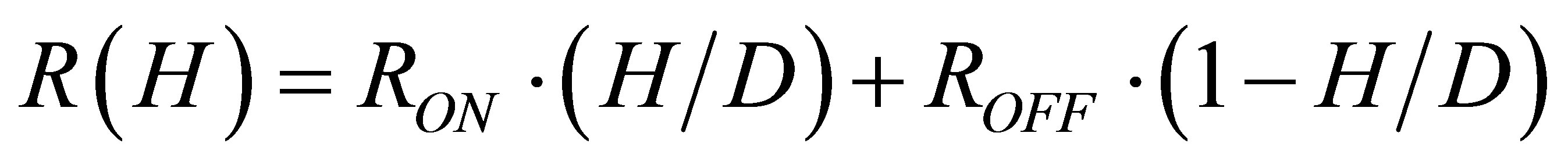 . (1)
. (1)
where  denotes the internal state variable (the width of doped area in the memristor), and
  denotes the whole thickness of the memristor,
  is the equivalent resistance of the memristor with respect to the internal variable.
In Figure 1, the model is derived from the topology of modified Chua’s circuit, where  denotes the conductance of a negative resistor, and
  is a positive linear resistor.
The dynamic in the circuit of Figure 1 is expressed by
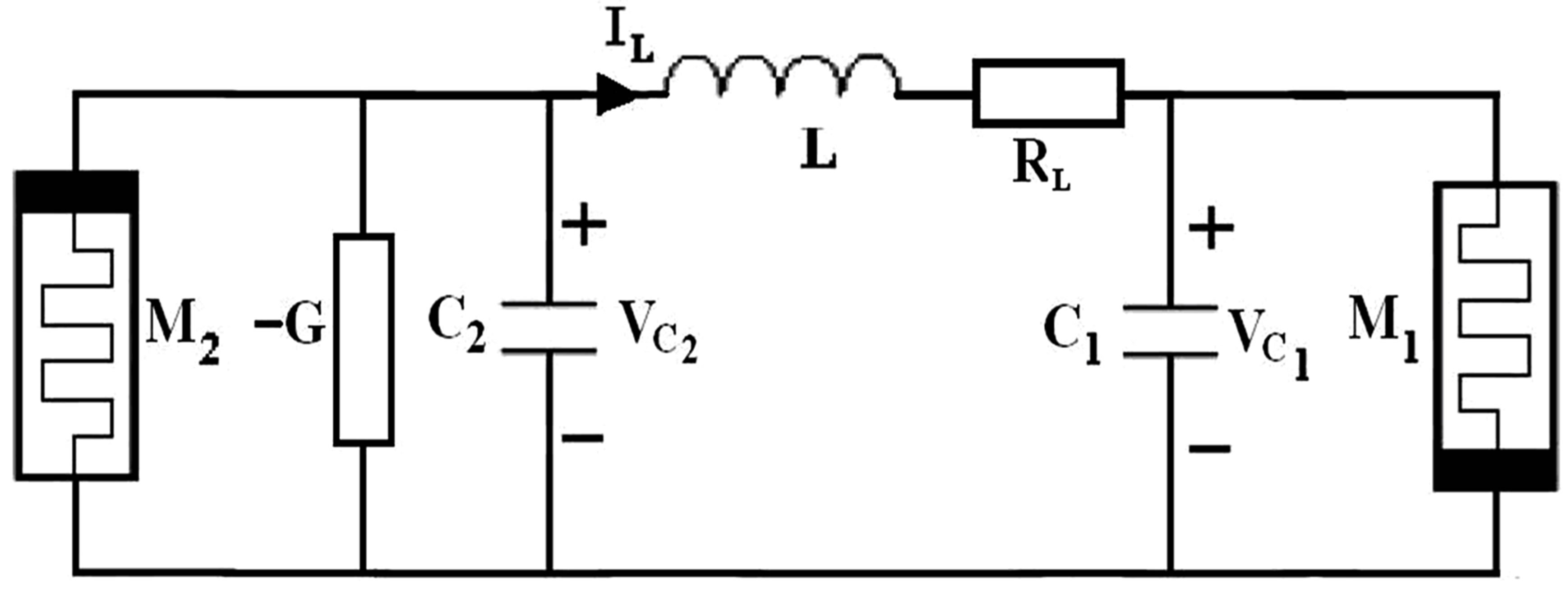
Figure 1. Schematic of a memristor-based circuit.
the following state equation as Equation (2):
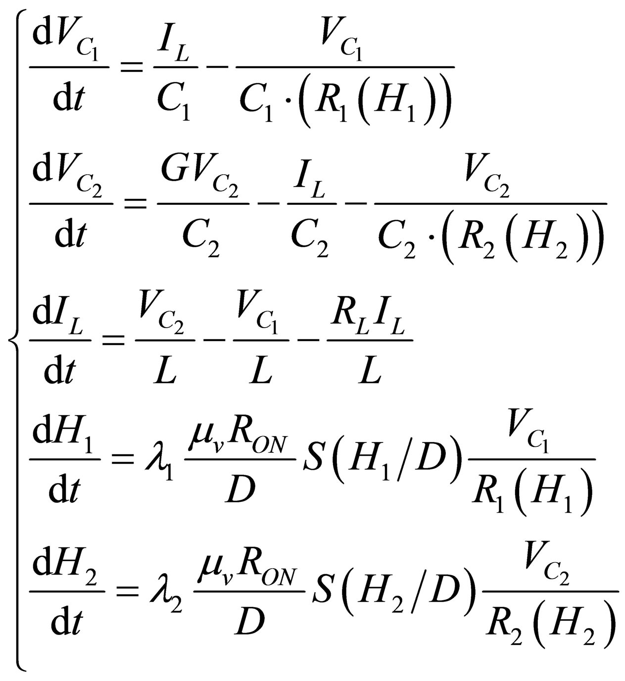 (2)
(2)
where R1(H1), R2(H2) denote the equivalent resistances of memristors M1, M2, respectively. And ,
,  are the window functions. There are different definitions about the window functions, such as the Strukov and collegues’ method [2], the Joglekar and Wolf’s method [13] and the Biolek and colleagues’ method [14]. We take the third one in this paper [14] (see Equation (3)).
 (3)
(3)
where  is a step function.
This paper aims at studying the memristor-based fractional order system. By one of the famous definitions of fractional order differential equations—Riemann Liouville (RL) definition [15], the fractional operater is described as Equation (4):
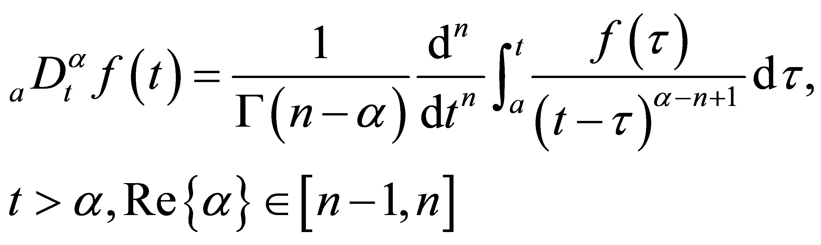 , (4)
, (4)
Then Equation (2) based on Figure 1 should be extended to the situation of fractional order system.
Let

the memristor-based fractional order system is transformed into a dimensionless form (5):
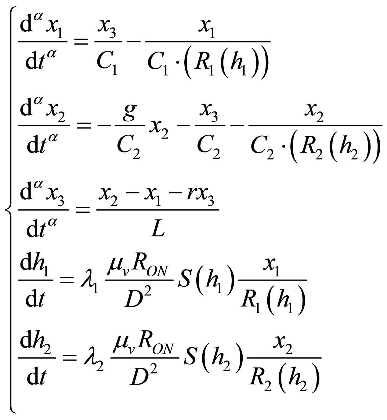 (5)
(5)
where the internal state variables h1, h2 of the memristor are still postulated as integer order differential equations.
3. Numerical Simulations
In this section, by using the approximation of fractional operator [16], we work out the solution of the fractional order differential Equation (5) in MATLAB. Figure 2 shows the chaotic dynamic characteristics of the system, where Figure 2(a)" target="_self">Figure 2(a) denotes the three-dimensional (3D) phase trace in x1-x2-x3 space of the fractional order system, Figure 2(b)" target="_self">Figure 2(b) denotes the 2D phase plots of the state variable x3 vs. x2, Figure 2(c) denotes the time evolution curve of state variable x1, Figure 2(d)" target="_self">Figure 2(d) is the phase plot of the state variable x1 vs. h1. We take the common values for some parameters in all the following simulations: the initial condition  and the initial position of the boundary of memristors
 , the fractional order a = 0.9, RON = 100, mv = 10−10, g = −0.0019.
In Figure 2, the other parameters are: C1 = 0.02, C2 = 0.01, L = 1800, r = 1425, ROFF = 15,000.
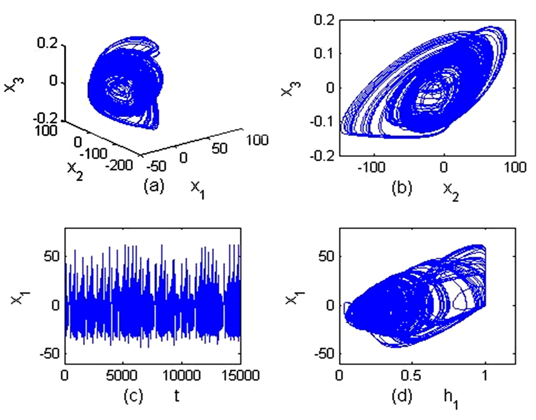
Figure 2. The strange attractor and time evolution of fractional order memristor-based system (5).
Figure 3 shows the phase trajectories of the memristor-based fractional order system in the various parameters C1, C2, L, ROFF. And in Figures 3(a)-(d), all the phase trajectories show the periodic dynamic properties of the system.
Figure 4 shows the time histories of internal state variables h1, h2 of memristors M1, M2, and the impedance of the memristor M1, where Figures 4(a), (c), (e) and (g) show the variations of the doped regions of two memristors M1, M2 andFigures 4(b), (d), (f) and (h) show the variations of the impedance of memristor M1. For the clarity of the figure, only the time varying impedance R1(h1) is shown in Figures 4(b), (d), (f), and (h). In additon to the above-mentioned common parameters, the impedance of memristor exhibits various changing trend under different circuit parameters.
From the simulation results, the memristor-based fractional order circuit shows different dynamical behaviors such as periodic and chaotic properties under different parameter conditions.
4. Synchronization
In this section, the synchronization between two memristor-based fractional order systems is discussed. Usually, synchronization is achieved to periodic orbit when the systems are originally in different periodic or chaotic conditions, sometimes they are synchronized to chaos when they are originally in different chaotic conditions. But here the drive system is assumed to be system (5) with the parameters C1 = 0.02, C2 = 0.01, L = 1800, mv = 10−10, g = −0.0019, r = 1425, RON = 100, ROFF = 15,000, and the response system is selected to be system
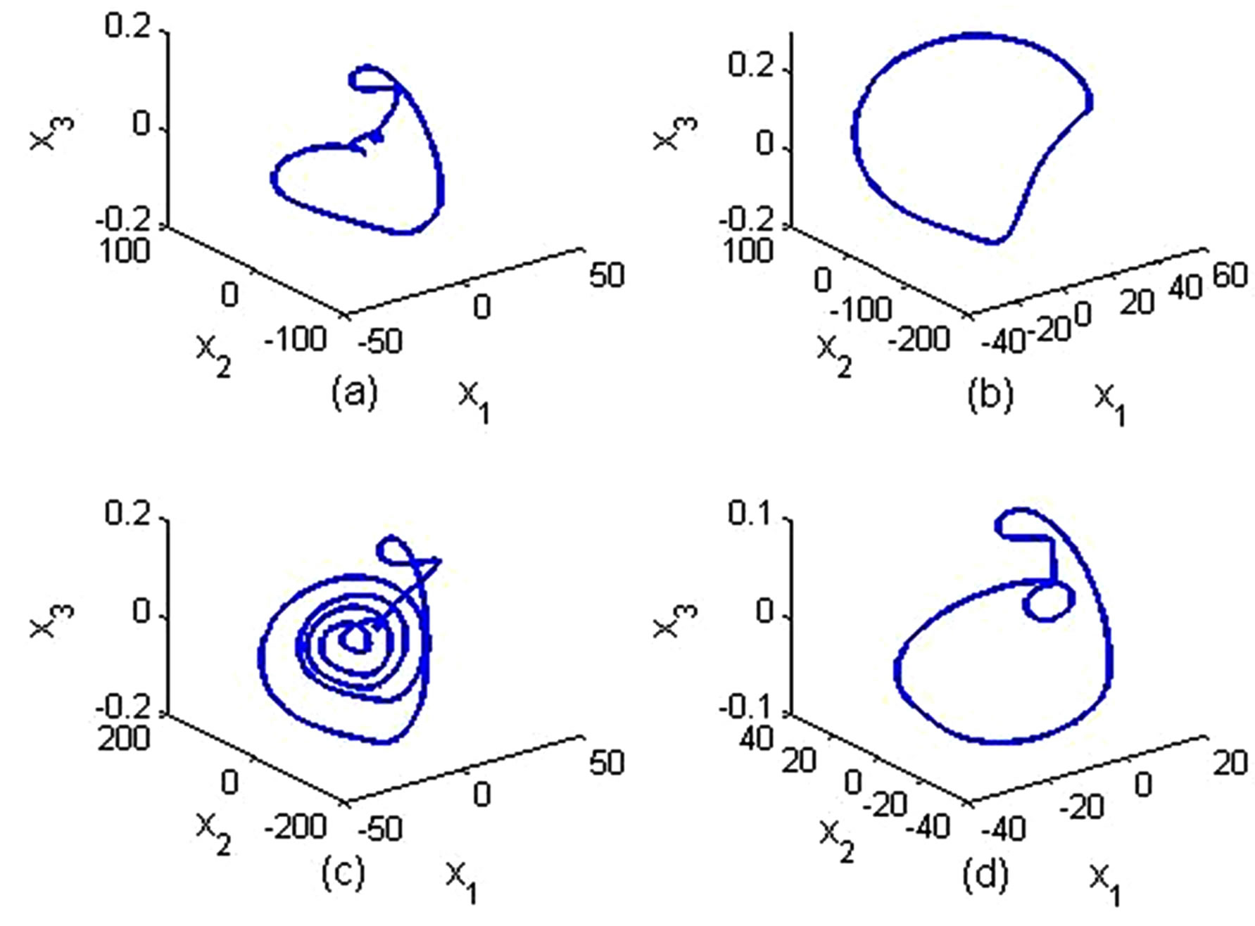
Figure 3. The phase trace of memristor-based fractional order system in x − y − z phase space with order a = 0.9, the initial values: (x10, x20, x30) = (0.01, 0.01, 0.01) and (h10, h20) = (0.01, 0.99), mv = 10−10, g = −0.0019, r = 1425, RON = 100 (Some transient points are ignored). (a) C1 = 0.01, C2 = 0.01, L = 1500, ROFF = 10,000; (b) C1 = 0.03, C2 = 0.01, L = 1800, ROFF = 15,000; (c) C1 = 0.02, C2 = 0.01, L = 1500, ROFF = 15,000; (d) C1 = 0.02, C2 = 0.02, L = 1800, ROFF = 15,000.
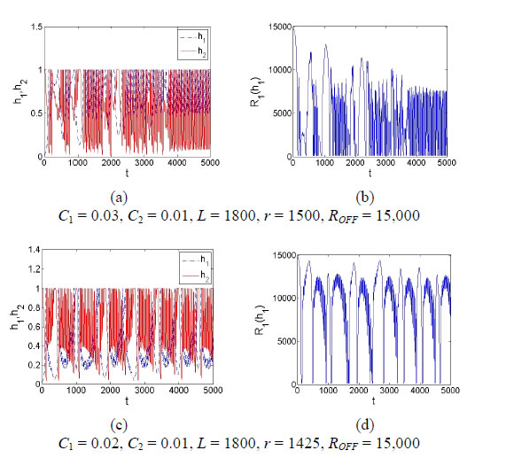
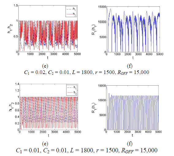
Figure 4. The time histories of doped regions and impedances of the memristors in fractional order system with order a = 0.9, the initial values: (x10, x20, x30) = (0.01, 0.01, 0.01), and (h10, h20) = (0.01, 0.99).
(5) with the parameters in C1 = 0.03, C2 = 0.01, L = 1800, mv = 10−10, g = −0.0019, r = 1425, RON = 100, ROFF = 15,000. That means the drive system is in chaotic state (see Figure 5(a)" target="_self">Figure 5(a)) and the response system displays periodic dynamics (see Figure 5(b)" target="_self">Figure 5(b)) when without control. Now the linear feedback control scheme is applied between these two systems as described by Equation (6). Figures 5(c) and (d) show that these two systems are finally synchronized to the chaotic state. The largest synchronization errors of three state variables
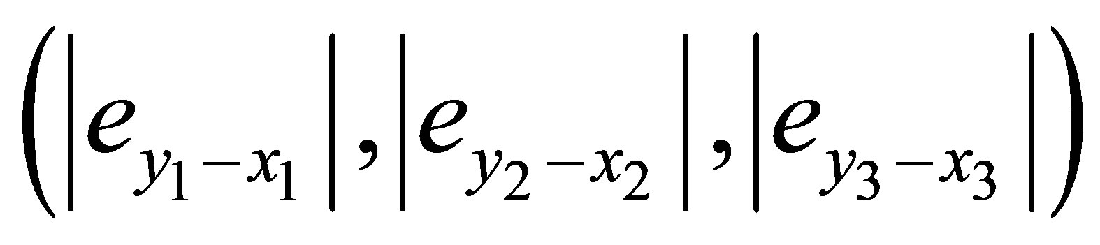 are less than 0.18, 3 × 10⁻⁵, 9 ×
10−6 while the control gain coefficients k1, k2, k3 are taken
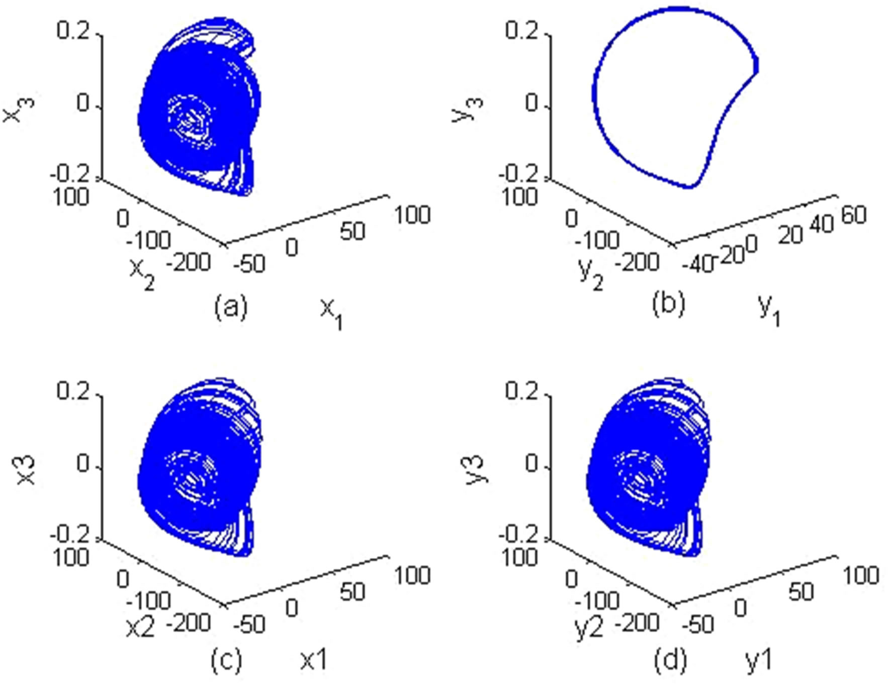
Figure 5. The synchronization of two memristor-based fractional order systems.
the values −40, −30, −10, respectively. And the largest synchronization errors are less than 0.035, 5 × 10⁻⁷, 8.5 × 10⁻⁷ while k1, k2, k3 are −200, −200, −20, respectively.
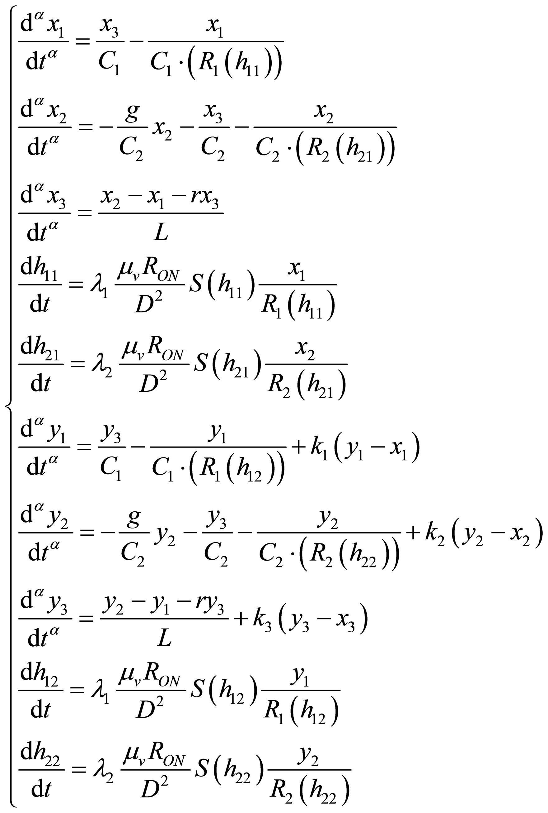 (6)
(6)
where h11, h21 are the relative doped widths of two memristors for the drive system, and h12, h22 denote the relative doped width of two memristors for the response system, respectively as shown in Figure 6" target="_self"> Figure 6.
5. Conclusion
In this paper, a generalized fractional order system model
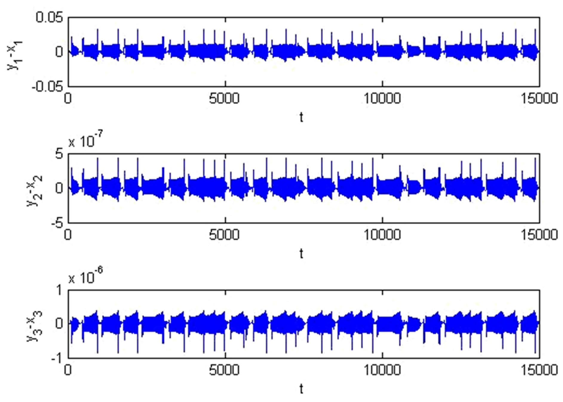
Figure 6. The synchronization errors of state variables between two memristor-based fractional order systems.
with two dispersedly distributed memristors is discussed. By varying the parameters of the circuit, different phase trajectories and time evolutions of state variables are observed. Also, it shows the correspondence between the mobility of the doped region and the time-varying impedance of the memristor in a series of circuit parameters. Simulation results verify the rich dynamic characteristics of the memristor-based fractional order system. Finally, two memristor-based fractional order systems originally in obviously different dynamic characteristics are synchronized. The next work is to study the circuit implementation and application in secure communication of the memristor-based fractional order system.
6. Acknowledgements
This work is supported by the National Natural Science Foundation of China under Grant No.61174025. The authors want to thank all the anonymous referees and editors for their valuable comments and suggestions.
REFERENCES
- L. O. Chua, “Memristor—The Missing Circuit Element,” IEEE Transactions on Circuit Theory, Vol. 18, No. 5, 1971, pp. 507-519. http://dx.doi.org/10.1109/TCT.1971.1083337
- D. B. Strukov, G. S. Snider, D. R. Stewart and R. S. Williams, “The Missing Memristor Found,” Nature, Vol. 453, No. 7191, 2008, pp. 80-83. http://dx.doi.org/10.1038/nature 06932
- K. C. Liu, W. H. Tzeng, K. M. Chang, et al. “The Resistive Switching Characteristics of a Ti/Gd2O3/Pt RRAM Device,” Microelectronics Reliability, Vol. 50, No. 5, 2010, pp. 670-673. http://dx.doi.org/10.1016/j.microrel.2010.02.006
- K. S. Vasu, S. Sampath and A. K. Sood, “Nonvolatile Unipolar Resistive Switching in Ultrathin Films of Graphene and Carbon Nanotubes,” Solid State Communications, Vol. 151, No. 16, 2011, pp. 1084-1087. http://dx.doi.org/10.1016/j.ssc.2011.05.018
- A. Kiazadeh, H. L. Gomes, A. M. R. Costa, et al., “Intrinsic and Extrinsic Resistive Switching in a Planar Diode Based on Silver Oxide Nanoparticles,” Thin Solid Films, Vol. 522, 2012, pp. 407-411. http://dx.doi.org/10.1016/j.tsf.2012.08.041
- B. Muthuswamy and P. P. Kokate, “Memristor-Based Chaotic Circuits,” IETE Technical Review, Vol. 26, No. 6, 2009, pp. 417-429. http://dx.doi.org/10.4103/0256-4602.57827
- Y. V. Pershin and M. Di Ventra, “Experimental Demonstration of Associative Memory with Memristive Neural Networks,” Neural Networks, Vol. 23, No. 7, 2010, pp. 881-886. http://dx.doi.org/10.1016/j.neunet.2010.05.001
- F. Z. Wang, H. Na, S. Wu, et al., “Delayed Switching in Memristors and Memristive Systems,” IEEE Electron Device Letters, Vol. 31, No. 7, 2010, pp. 755-757. http://dx.doi.org/10.1109/LED.2010.2049560
- A. Talukdar, A. G. Radwan and K. N. Salama, “Non Linear Dynamics of Memristor Based 3rd Order Oscillatory System,” Microelectronics Journal, Vol. 43, No. 3, 2012, pp. 169-175. http://dx.doi.org/10.1016/j.mejo.2011.12.012
- A. Buscarino, L. Fortuna, M. Frasca and L. V. Gambuzza, “A Chaotic Circuit Based on Hewlett-Packard Memristor,” Chaos, Vol. 22, No. 2, 2012, Article ID: 023136. http://dx.doi.org/10.1063/1.4729135
- I. Petráš, “Fractional-Order Memristor-Based Chua’s Circuit,” IEEE Transactions on Circuits and Systems—II: Express Briefs, Vol. 57, No. 12, 2010, pp. 975-979. http://dx.doi.org/10.1109/TCSII.2010.2083150
- S. P. Wen, Z. G. Zheng and T. W. Huang, “Adaptive Synchronization of Memristor-Based Chua’s Circuits,” Physics Letters A, Vol. 376, No. 44, 2012, pp. 2775-2780. http://dx.doi.org/10.1016/j.physleta.2012.08.021
- Y. N. Joglekar and S. J. Wolf, “The Elusive Memristor: Properties of Basic Electrical Circuits,” European Journal of Physics, Vol. 30, No. 4, 2009, pp. 661-675. http://dx.doi.org/10.1088/0143-0807/30/4/001
- Z. Biolek, D. Biolek and V. Biolkova, “SPICE Model of Memristor with Nonlinear Dopant Drift,” Radioengineering, Vol. 18, No. 2, 2009, pp. 210-214.
- I. Podlubny, “Fractional Differential Equations,” Academic Press, San Diego, 1999.
- T. T. Hartley, C. F. Lorenzo and H. K. Qammar, “Chaos in a Fractional Order Chua’s System,” IEEE Transactions on Circuits and Systems I-Fundamental Theory and Applications, Vol. 42, No. 8, 1995, pp. 485-490. http://dx.doi.org/10.1109/81.404062
NOTES
*Corresponding author.