Open Journal of Civil Engineering
Vol.2 No.3(2012), Article ID:22985,7 pages DOI:10.4236/ojce.2012.23018
Achievements of Truss Models for Reinforced Concrete Structures
Department of Civil Engineering, Aristotle University of Thessaloniki, Thessaloniki, Greece
Email: panaggpapad@yahoo.gr, xharis@civil.auth.gr, pl@civil.auth.gr
Received April 9, 2012; revised May 10, 2012; accepted May 24, 2012
Keywords: Reinforced Concrete Structure; Truss Model; Constitutive Law; Material and Geometric Nonlinearities; Concrete Cracking; Reinforcement Yield; Concrete Ultimate Compressive Strength; Plastic Hinge; RC Column Confinement; Buckling of Inner Concrete Struts; Global Instability
ABSTRACT
Achievements are presented for truss models of RC structures developed in previous years: 1) Two constitutive models, biaxial and triaxial, are based on regular trusses, with bars obeying nonlinear uniaxial σ-ε laws of material under simulation; both models have been compared with test results and show a dependence of Poisson ratio on curvature of σ-ε law; 2) A truss finite element has been used in the nonlinear static and dynamic analysis of plane RC frames; it has been compared with test results and describes, in a simple way, the formation of plastic hinges; 3) Thanks to the very simple geometry of a truss, the equilibrium equations can be easily written and the stiffness matrix can be easily updated, both with respect to the deformed truss, within each step of a static incremental loading or within each time step of a dynamic analysis, so that to take into account geometric nonlinearities. So the confinement of a RC column is interpreted as a structural stability effect of concrete. And a significant role of the transverse reinforcement is revealed, that of preventing, by its close spacing and sufficient amount, the buckling of inner longitudinal concrete struts, which would lead to a global instability of the RC column; 4) The proposed truss model is statically indeterminate, so it exhibits some features, which are not met by the “strut-and-tie” model.
1. Introduction
In 1967, in a pioneering work [1], D. Ngo and A. C. Scordelis presented a detailed finite element model for a RC beam, in which separate finite elements are used for concrete and steel reinforcement. The material nonlinearities of the reinforcement can be easily described by the nonlinear uniaxial σ-ε law of a bar element. However, it is difficult to represent the nonlinear biaxial or triaxial stress-strain behavior of concrete or any other material. The relevant problems are discussed in two state-of-theart reports on nonlinear finite element analysis of RC structures, one by P. G. Bergan and I. Holand in 1979 [2] and another in a special publication of ASCE in 1982 [3], written by specialists on this field, under the co-ordination of A. C. Scordelis. Also, the difficulties appearing in the application of finite elements to nonlinear problems have been discussed in the series of three Conferences F. E. No. Mech. (Finite Elements in Nonlinear Mechanics), organized by J. H. Argyris in the Institute of Statics and Dynamics, University of Stuttgart, Germany in the years 1978, 1981, 1984 [4].
In order to describe the nonlinear biaxial or triaxial stress-strain behavior of a structure by the Finite Element Method, constitutive models for the structural materials have to be developed in order to be embodied in the individual finite elements. Efforts to develop such constitutive models have been made by many researchers, e.g. plasticity models by W. F. Chen [5] and Z. Mroz [6], the plastic-fracturing model of Z. P. Bazant [7], as well as the more practical contributions by D. Darwin [8] and K. I. Willam [9], for nonlinear, biaxial and triaxial, respectively, stress-strain behavior of concrete.
In 1977 [10], N. J. Burt and J. W. Dougill presented a random network constitutive model, in order to describe the nonlinear biaxial stress-strain law of a material, and noticed that equivalent results can be obtained by use of simple regular networks. By applying this idea, P. G. Papadopoulos developed in 1984 and 1986 [11,12] a biaxial and a triaxial network constitutive model, based on a regular plane octagon and a regular space rhombic dodecahedron, respectively, in which sides and diagonals are bars obeying the nonlinear uniaxial σ-ε laws of the material under simulation. Results from the above network constitutive models have been found in satisfactory approximation with corresponding published test results [13-15].
Trusses have been used not only in constitutive models, but also in finite elements of structures. In 1978 [16], E. Absi, in his “theorie des equivalences” stated that simple truss finite elements give equivalent results with the usual more complicated continuum finite elements. This idea was extended to problems with material nonlinearities and to the nonlinear static and dynamic analysis of plane RC frames by P. G. Papadopoulos [17,18]. A simple truss finite element was proposed, based on a plane rectangle in which all sides and diagonals are bars obeying nonlinear uniaxial σ-ε laws of concrete or steel. So, the nonlinear biaxial stress-strain behavior of the element is, in a simple way, described, thus the embodying of a constitutive law in the individual finite elements is no more needed. Results from nonlinear static analysis for cyclic loading, as well as nonlinear seismic dynamic analysis of simple plane RC frames, by the proposed truss RC element, were compared with corresponding published test results and found in a satisfactory approximation with them [19,20]. As the bars of the proposed finite element include the main material nonlinearities of concrete and steel, that is concrete tensile cracking and ultimate compressive strength, as well as tensile yield of reinforcement, the proposed truss model can, in a simple way, describes the formation of plastic hinges in a RC frame.
Afterwards, some other versions of E. Absi ideas for truss finite elements were developed for plane structures, under various names but all similar to each other, e.g. “truss analogy” in 1997 [21] for steel structures, “lattice model” in 1997 [22] and “lumped stress model” in 2002 [23], the latter two for RC structures.
In 1987 [24] J. Schlaich invented the so called “strutand-tie” model, which is a statically determinate truss model, consisting of concrete and steel bars. These bars include the main material nonlinearities of a RC structure. So, the “strut-and-tie” model can effectively describe the main stress-strain states of a RC structure, that is bending, shear and even torsion in 3D, thus it has been proved as a very useful practical tool in analysis and design of RC structures.
The “strut-and-tie” model has been further developed by other researchers, as by T. T. Hsu in 1993 [25], by F. J. Vecchio and M. P. Collins in 1993 [26], as well as by ASCE-ACI Committee on shear and torsion in 1998 [27].
The proposed here truss model is a statically indeterminate structure, so it exhibits some features that are not met by the statically determinate “strut-and-tie” model:
1) It can describe lateral expansion (Poisson ratio) effect.
2) It takes into account geometric nonlinearities, by writing the equilibrium equations and updating the stiffness matrix, both with respect to the deformed truss, within each step of a static incremental loading or within each time step of a dynamic analysis. This is easily achieved thanks to the very simple geometry of a truss.
By this proposed truss model which includes geometric nonlinearities, the confinement of a RC column is interpreted as a structural stability effect of concrete [28-30].
And, beyond the already known roles of the transverse reinforcement [31-33] (that is, shear transfer, reduction of concrete spalling, preventing of buckling of longitudinal reinforcement, increase of compressive stiffness, strength and ductility of the confined concrete core), another significant role of the transverse reinforcement is revealed by the proposed truss model with structural instability, that of retarding and even preventing, by its close spacing and sufficient amount, the buckling of inner longitudinal concrete struts, which would lead to a global instability of the RC column.
Results from the application of this proposed model with structural instability on RC column confinement have been found in a satisfactory approximation to Codes requirements [34-36], regarding the spacing and amount of transverse reinforcement, which, in turn, are based on test results, too.
In the following, some of the achievements of the above proposed truss models for nonlinear analysis of structures, mainly RC structures, proposed in previous years, will be described in more detail.
2. Truss Constitutive Models
A biaxial and a triaxial constitutive model for the nonlinear stress-strain law of a material have been developed [11,12], based on a regular plane octagon and a regular space rhombic dodecahedron, respectively, in which sides and diagonals are bars obeying the nonlinear uniaxial σ-ε law of the material under simulation. So, in a simple way, by the nonlinear uniaxial σ-ε laws of the bars, the nonlinear biaxial or triaxial stress-strain behavior of the whole truss is described. Results from the above truss constitutive models, for various loading histories, have been found in satisfactory approximation to corresponding published test results [13-15]. Both above truss constitutive models show a dependence of the Poisson ratio value ν on the curvature κ of the nonlinear uniaxial σ-ε law of the material under consideration, as shown in Figure 1.
3. Truss Finite Element for Plane RC Frame
A truss finite element is proposed for beams of a plane RC frame, based on a rectangle, in which all sides and diagonals are bars, obeying nonlinear uniaxial σ-ε laws of concrete or steel, as shown in Figure 2. The σ-ε law of concrete bars includes tensile cracking, ultimate compressive strength, as well as loading-unloading rules after compressive yield. Whereas, the σ-ε law of a steel bar includes ultimate tensile and compressive strengths, as well as loading-unloading rules after tensile or compressive yielding.
4. Determination of Bar Sections
In the above proposed truss finite element for beams of plane RC frames, the cross-section areas of steel bars are reasonably and easily determined as sums of sections of the corresponding steel reinforcing bars. Whereas, in order to determine the cross-sections areas A1, A2, A3 of the concrete bars of the truss element as shown in Figure 3(b), we have to compare it to the corresponding continuum concrete beam element of Figure 3(a), as regards three representative stress-strain states in the linear elastic region. And we chose, as such characteristic states, the pure bending, the confined axial deformation as well as the confined transverse deformation.
For the pure bending shown in Figure 3(c), the curvature angle of the beam element is 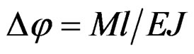 where
where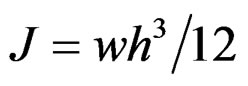 , whereas for the truss element
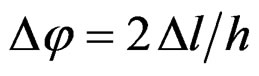
where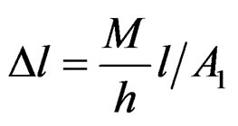 . By combining the above equations we obtain
 .
.

Figure 1. Dependence of Poisson ratio ν on the curvature κ of nonlinear uniaxial σ-ε law of the material. (a) Metal κ = 0 g v = 1/3; (b) Geologic material e.g. concrete κ < 0 g ν < 1/3; (c) Rubber-like material κ > 0 g ν > 1/3.

Figure 2. (a) Truss finite element for beam of a plane RC frame, with concrete and steel bars; (b) Nonlinear uniaxial σ-ε law of concrete bars; (c) Nonlinear uniaxial σ-ε law of steel bars.

Figure 3. Comparison between characteristic stress-strain states of the concrete beam element and the corresponding truss element in order to determine the concrete bar sections. (a) Concrete beam element; (b) Corresponding truss element; (c) Pure bending; (d) Confined axial compression.
For the confined axial deformation, the elasticity theory gives .
.
For , thus
  where
where  and
and . In the corresponding state of the truss element shown in Figure 3(d), we have
where 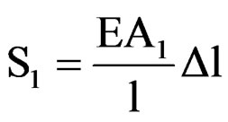 and
and  .
.
From combination of above equations, we obtain
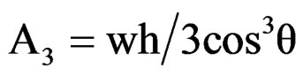
From similar considerations for confined transverse deformation, we obtain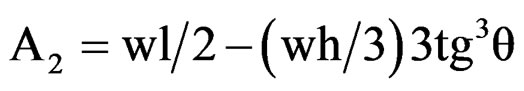 .
.
Obviously, when the angle θ tends to zero, θ → 0, the sections tend to A3→ and A2→
 .
.
5. Nonlinear Static Analysis
The incremental loading of the structure is preferably performed by strain control, which is a more stable procedure than stress control. The material nonlinearities are taken into account by the variations of the elasticity moduli E of the bars during the loading. Whereas, in order to take into account geometric nonlinearities, the equilibrium equations are written and the global stiffness matrix updated, both with respect to the deformed truss, within each step of incremental loading. The local stiffness matrix of a bar in 2D, consisting of elastic and geometric part, is:
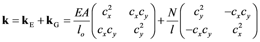
where A section, lo undeformed length, l present length, N axial force and cx, cy direction cosines of the bar.
Whereas, the global stiffness matrix of the truss is:

where B Boolean linkage matrix and nb number of bars of the truss.
Based on the proposed algorithm, a very short computer program, with only about 200 FORTRAN instructions, has been developed, for the nonlinear static analysis of a truss model of a plane RC frame.
6. Nonlinear Dynamic Analysis
A lumped mass is assigned to every free node of the truss. Zero damping and zero initial velocities are assumed. The resulting initial value problem:
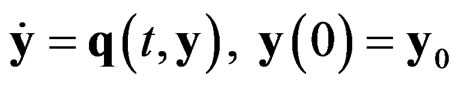 where the state vector is
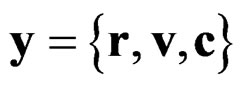 with r, v positions and velocities of nodes and c constitutive variables of the bars, is solved by the step-by-step algorithm of trapezoidal rule, which coincides with the Newmark’s algorithm of constant average acceleration:
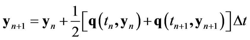 combined with a predictor-corrector technique with two corrections per step, PE(CE)2 [37]. So, there is no need to solve an algebraic system within each step of the algorithm.
The stability criterion of the algorithm is  rad and the accuracy criterion is
 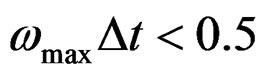 rad, that is
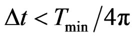 , which dictates the choosing of the time step-length Δt of the algorithm.
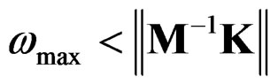
An upper bound for the normal frequencies can be found from the norm of the matrix M–1K, where M mass matrix and K stiffness matrix of the structure:
Based on the proposed algorithm, a very short computer program has been developed, with only about 150 FORTRAN instructions, for the nonlinear dynamic analysis of a truss model of a RC frame.
7. Applications to Analysis of Simple Plane RC Frames
The above proposed truss finite element for plane RC frames, as well as the proposed algorithms for nonlinear static and dynamic analysis, have been applied to the nonlinear static analysis of a simple plane RC frame for cyclic loading [17], as well as to the nonlinear dynamic seismic analysis of a simple plane RC frame [18]. The results of these analyses have been found in satisfactory approximation with corresponding published test results [19,20].
As the nonlinear uniaxial σ-ε laws, of the bars of the proposed truss model, include all the main material nonlinearities of a RC structure, that is tensile cracking and ultimate compressive strength of concrete, as well as tensile yielding of steel reinforcement, the formation of plastic hinges in a RC frame is, in a simple way, described, as shown in Figure 4.
8. Application to Confinement of a RC Column
In order to take into account geometric nonlinearities, by the proposed truss model, the equilibrium equations are written and the stiffness matrix is updated, both with respect to the deformed truss, within each step of a static incremental loading or within each time step of a dynamic analysis. This is easily achieved thanks to the very simple geometry of a truss.
As the proposed truss model includes geometric nonlinearities, it interprets the confinement of a RC column as a structural stability effect of concrete [28-30].
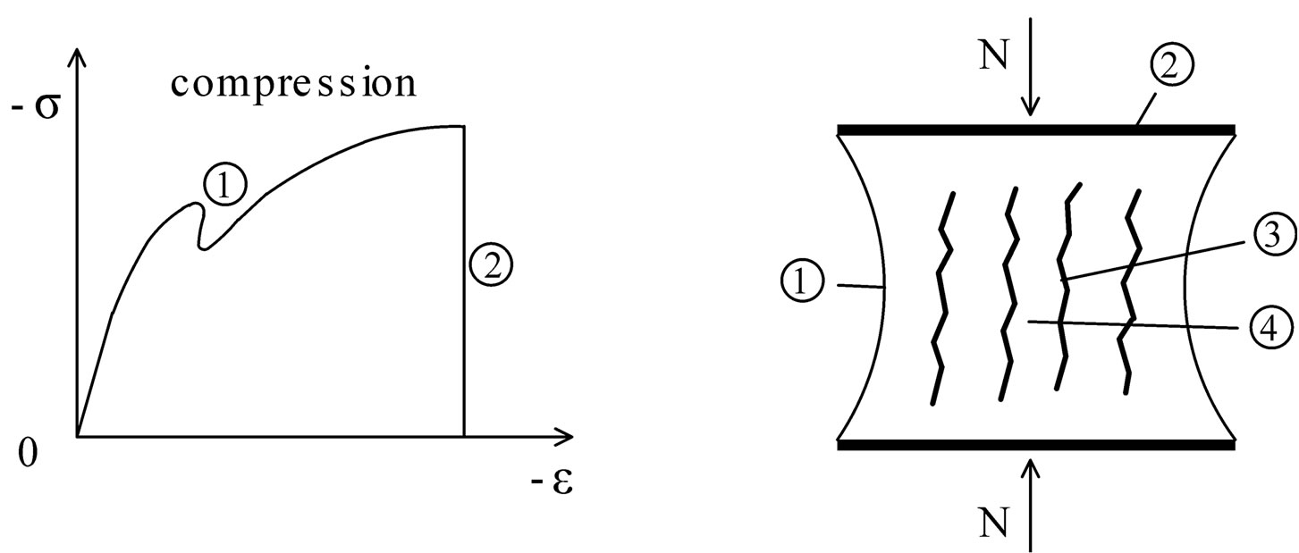
In Figure 5(a), the compressive axial σ-ε diagram of a confined RC column is shown. An early small drop of the stress  is observed, which is due to a local instability because of spalling (buckling) of outer concrete. As the loading further increases, preferably by strain control, for a significant value of the compressive axial deformation, the stress σ suddenly drops to zero, which is an obvious mark of global structural instability, observed in experiments and verified by the proposed truss model, too.
In Figure 5(b), a part of a confined RC column, between two successive sets of transverse reinforcement, is shown. The longitudinal reinforcement is omitted, for simplicity. As the compressive axial loading N gradually increases, a lateral expansion of concrete occurs. For a significant compressive axial deformation, because of the large lateral expansion of concrete, a tensile yielding of the transverse reinforcement occurs, which implies a
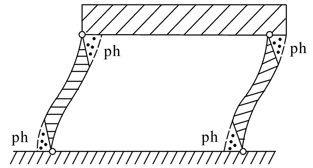
Figure 4. Description of formation of plastic hinges, in a RC frame, by the proposed truss model. “…...” cracked concrete. “------” reinforcement in tensile yielding. “//////” rigid parts. “ph” plastic hinges.
 (a) (b)
Figure 5. (a) Compressive axial σ-ε diagram of a confined RC column. 1. Early small drop of stress due to spalling of outer concrete. 2. For a significant value of compressive axial deformation, the stress σ suddenly drops to zero, which is a mark of global structural instability; (b) A part of a confined RC column between two successive sets of transverse reinforcement. 1. Spalling of outer concrete. 2. Transverse reinforcement in tensile yielding. 3. Longitudinal concrete cracks. 4. Longitudinal concrete struts.
further lateral expansion of concrete. So, wide longitudinal-vertical concrete cracks are formed, and between such successive concrete cracks, inner longitudinal-vertical concrete struts are formed, which tend to buckle, leading to a global instability of the RC column.
Beyond the already known roles of transverse reinforcement in a RC column [31-33] (that is shear transfer, reduction of concrete spalling, preventing of buckling of longitudinal reinforcement, increase of compressive axial stiffness, strength and ductility of the confined concrete core), another significant role of the transverse reinforcement is revealed by the proposed truss model with structural instability, that of retarding and even preventing, by its close spacing s and sufficient amount ρ (mechanical ratio), the buckling of the above inner longitudinal-vertical concrete struts, which would lead to a global instability of the RC column.
Results, from application of the proposed truss model with structural instability to the confinement of RC columns, have been found in satisfactory approximation with corresponding requirements of codes [34-36], regarding the spacing s and the mechanical ratio ρ of transverse reinforcement; these requirements are, in turn, based on test results, too.
9. Conclusions
Some achievements have been presented for truss models of structures, mainly RC structures, which have been developed in previous years and found in satisfactory approximation with test results and Codes requirements:
1) N. J. Burt and J. W. Dougill developed in 1977 [10] random network constitutive models and stated that equivalent results can be, in a simple way, obtained by regular networks. This idea was realized in 1984 [11] and 1986 [12] by two network constitutive models, a biaxial and triaxial one, based on a regular plane octagon and on a regular space rhombic dodecahedron, respectively, in which sides and diagonals are bars obeying the nonlinear uniaxial σ-ε law of the material under simulation. Both models show a dependence of Poisson ratio on the curvature of the nonlinear uniaxial σ-ε law of the material.
2) E. Absi in 1978 [16], in his “theorie des equivalences”, stated that simple truss finite elements give equivalent results with the usual more complicated continuum finite elements. This idea was extended in 1988 [17,18] to structures with material nonlinearities, and applied particularly to the nonlinear static and dynamic analysis of plane RC frames. As the individual bars of the proposed truss finite element include, in their uniaxial σ-ε laws, the main material nonlinearities of a RC structure, that is the concrete tensile cracking, the reinforcement tensile yield, as well as the ultimate compressive strength of concrete, the formation of plastic hinges in a RC frame can be, in a simple way, described.
3) Compared to the “strut-and-tie” model for RC structures, invented by J.Schlaich in 1987 [24] and further developed by other researchers, which proved as a very effective tool in the analysis of RC structures, the proposed here truss model exhibits the difference that it is a statically indeterminate, whereas the “strut-and-tie” model is statically determinate. So, the proposed truss model has some features that are not met by the “strut-and-tie” model: a) It can describe lateral expansion (Poisson ratio) effect. b) It takes into account geometric nonlinearities, by writing equilibrium equations and by updating stiffness matrix, both with respect to the deformed truss, within each step of a nonlinear static or dynamic analysis. So, it interpreted in 1999 [31] the confinement of a RC column as a structural stability effect of concrete. And revealed a significant role of transverse reinforcement, that of retarding and even preventing, by its close spacing and sufficient amount, the buckling of inner longitudinal concrete struts, which would lead to a global instability of the RC column.
REFERENCES
- D. Ngo and A. C. Scordelis, “Finite Element Analysis of Reinforced Concrete Beams,” ACI Journal, Vol. 64, 1967, pp. 152-163.
- P. G. Bergan and I. Holand, “Nonlinear Finite Element Analysis of Concrete Structures,” Computer Methods in Applied Mechanics and Engineering, Vol. 17-18, 1979, pp. 443-467. doi:10.1016/0045-7825(79)90027-6
- A. C. Scordelis, Editor, ASCE Task Committee on Concrete and Masonry Structures, “State-of-the-Art Report on Finite Element Analysis of Reinforced Concrete,” ASCE Special Publication, 1982.
- J. H. Argyris, Organizer, International Conferences F.E.No.Mech. (Finite Elements in Nonlinear Mechanics). Institute for Statics and Dynamics, University of Stutgart, Germany, I.30 August-1 September 1978, II. 25-28 August 1981. III. 10-13 September 1984.
- W. F. Chen and E. C. Ting. “Constitutive Models for Concrete Structures,” Journal of Engineering Mechanics Division ASCE, Vol. 106, No. 1, 1980, pp. 1-19.
- Z. Mroz, V. A. Norris and O. C. Zienkiewicz, “Application of an Anisotropic Hardening Model in the Analysis of Elastic-Plastic Deformation of Soils,” Geotechnique, Vol. 29, 1979, pp. 1-34. doi:10.1680/geot.1979.29.1.1
- Z. P. Bazant and S. S. Kim, “Plastic-Fracturing Theory for Concrete,” Journal of Engineering Mechanics Division ASCE, Vol. 105, No. 3, 1979, pp. 407-428.
- D. Darwin and D. A. Pecknold, “Analysis of Cyclic Loading of RC Structures,” Computers and Structures, Vol. 7, No. 1, 1977, pp. 137-147. doi:10.1016/0045-7949(77)90068-2
- K. J. Willam and E. P. Warnke, “Constitutive Model for the Triaxial Behavior of Concrete,” Proceedings of IABSE, Structural Engineering Report 19, Section III, 1975, pp. 1-30.
- N. J. Burt and J. W. Dougill, “Progressive Failure in a Model Heterogeneous Medium,” Journal of Engineering Mechanics Division ASCE, Vol. 103, 1977, pp. 365-376.
- P. G. Papadopoulos, “Biaxial Network Constitutive Model,” Journal of Engineering Mechanics ASCE, Vol. 110, No. 3, 1984, pp. 449-464. doi:10.1061/(ASCE)0733-9399(1984)110:3(449)
- P. G. Papadopoulos, “A Triaxial Network Constitutive Model,” Computers and Structures, Vol. 23, 1986, pp. 497-501. doi:10.1016/0045-7949(86)90093-3
- H. B. Kupfer, H. D. Hilsdorf and H. Rusch, “Behavior of Concrete under Biaxial Stresses,” ACI Journal, Vol. 66, No. 8, 1969, pp. 656-666.
- R. Palaniswamy and S. P. Shah, “Fracture and StressStrain Relationships of Concrete under Triaxial Compression,” Journal of Structural Division ASCE, Vol. 100, 1974, pp. 901-916.
- R. Scavuzzo, T. Stankowski, K. Gerstle and H.-Y. Ko, “Stress-Strain Curves for Concrete under Multiaxial Load Histories,” University of Colorado, Boulder, 1983.
- E. Absi, “Méthodes des Calcus Numerique en Elasticité,” Eyrolles, Paris, 1978.
- P. G. Papadopoulos, “Nonlinear Static Analysis of Reinforced Concrete Frames by Network Models,” Advances in Engineering Software, Vol. 110, No. 3, 1988, pp. 114- 122. doi:10.1016/0141-1195(88)90010-1
- P. G. Papadopoulos and C. G. Karayannis, “Seismic Analysis of R/C Frames by Network Models,” Computers and Structures, Vol. 28, No. 4, 1988, pp. 481-494. doi:10.1016/0045-7949(88)90022-3
- K. Stylianidis and G. Penelis, “Experimental Study of, bare and Infilled by Wall, One Story Frames under Cyclic shear Loading,” 7th Greek Conference on Concrete, Vol. 2, Patra, 1985, pp. 47-55.
- P. Hidalgo and R. W. Clough, “Earthquake Simulator Study of a Reinforced Concrete Frame,” EERC Report 74-13, University of California, Berkeley, 1974.
- S. C. Goel, B. Stojadinovicz and K. H. Lee, “Truss Analogy for Steel Moment Connections,” Engineering Journal, Second Quarter 1997, pp. 43-53.
- E. Schlangen and E. J. Garboczi, “Fracture Simulations of Concrete Using Lattice Models: Computational Aspects,” Engineering Fracture Mechanics, Vol. 57, No. 2-3, 1997, pp. 319-332. doi:10.1016/S0013-7944(97)00010-6
- F. Fraternali, M. Angelilo and A. Fortunato, “A Lumped Stress Method for Plane Elastic Problems and the Discrete Continuum Approximation,” International Journal of Solids and Structures, Vol. 39, 2002, pp. 6211-6240. doi:10.1016/S0020-7683(02)00472-9
- J. Schlaich, K. Schäfer and M. Jennewein, “Towards a Consistent Design of Structural Concrete,” PCI Journal Special Report, Vol. 32, No. 3, 1987, pp. 75-150.
- T. T. C. Hsu, “Unified Theory of Reinforced Concrete,” CRC Press, 1993.
- F. J. Vecchio and M. P. Collins, “Compression Response of Cracked Reinforced Concrete,” Journal of Structural Engineering ASCE, Vol. 113, 1993, pp. 3590-3610. doi:10.1061/(ASCE)0733-9445(1993)119:12(3590)
- ASCE-ACI Committee 445 on Shear and Torsion, “Recent Approaches to Shear Design of Structural Concrete. State-of-the-Art Report,” Journal of Structural Engineering ASCE, Vol. 119, No. 12, 1998, pp. 1375-1417.
- P. G. Papadopoulos and H. C. Xenidis, “A Truss Model with Structural Instability for the Confinement of Concrete Columns,” Journal of EEE (European Earthquake Engineering), Part 2, 1999, pp. 57-79.
- P. G. Papadopoulos, H. Xenidis, C. Karayannis, A. Diamantopoulos and P. Lambrou, “Confinement of Concrete Column Interpreted as a Structural Stability Effect,” 6th GRACM (Greek Association of Computational Mechanics) Conference, Thessaloniki, 19-21 June 2008.
- P. G. Papadopoulos, H. Xenidis, D. Plasatis, P. Kiousis and C. Karayannis, “Concrete Stability Achieved by Confinement in a RC Column,” 12th International Conference on Civil, Structural and Environmental Engineering Computing, Coordinator B.H.V. Topping, Madeira, Portugal, 1-4 September 2009.
- K. Park, M. J. N. Priestley and W. D. Gill, “Ductility of Square Confined Concrete Columns,” Journal of Structural Division ASCE, Vol. 108, No. 4, 1982, pp. 929-950.
- S. Watson, F. A. Zahn and R. Park, “Confining Reinforcement for Concrete Columns,” Journal of Structural Engineering ASCE, Vol. 120, No. 6, 1984, pp. 1798- 1849.
- J. B. Mander, M. J. N. Priestley and R. Park, “Theoretical Stress-Strain Model for Confined Concrete,” Journal of Structural Engineering ASCE, Vol. 114, No. 8, 1988, pp. 1804-1826. doi:10.1061/(ASCE)0733-9445(1988)114:8(1804)
- Uniform Building Code 2, “Structural Engineering Design Provisions,” Chapter 19. Concrete, 19.2.1. Reinforced Concrete Structures Resisting Forces Induced by Earthquake Motions 19.2.14. Frame Members Subjected to Bending and Axial Load, 1994, pp. 237-239.
- New Zealand Standards 3101, “Code of Practice for the Design of Concrete Structures,” Chapter 17, Members Subjected to Flexure and Axial Loads, Additional Seismic Requirements, 1989.
- Eurocode 8, “Earthquake Resistant Design of Structures,” Part 1-3. General Rules and Rules for Buildings. 2, Specific Rules for Concrete Buildings. 2.8. Provisions for Columns, Brussels, 1993, pp. 35-46.
- P. G. Papadopoulos, “A Simple Algorithm for the Nonlinear Dynamic Analysis of Networks,” Computers and Structures, Vol. 18, No. 1, 1984, pp. 1-8. doi:10.1016/0045-7949(84)90074-9