Optics and Photonics Journal
Vol.3 No.2(2013), Article ID:32727,6 pages DOI:10.4236/opj.2013.32027
Performance Analysis of WDM RoF-EPON Link with and without DCF and FBG
1Department of Electronics and Communication Engineering, Guru Nanak Dev Engineering College, Ludhiana, India
2Department of Computer Science and Engineering, National Institute of Technology, Jalandhar, India
3Department of Electronics and Communication Engineering, National Institute of Technology, Hamirpur, India
Email: baljeetkaur@gndec.ac.in, sharmaajayk@nitj.ac.in, kapoor@nitham.ac.in
Copyright © 2013 Baljeet Kaur et al. This is an open access article distributed under the Creative Commons Attribution License, which permits unrestricted use, distribution, and reproduction in any medium, provided the original work is properly cited.
Received March 8, 2013; revised April 10, 2013; accepted April 17, 2013
Keywords: Optical Network Unit; Optical Line Termination; BER; EPON; RoF; DCF; FBG
ABSTRACT
Performance of WDM ethernet passive optical network (EPON) with radio over fiber (RoF) optical link has been analyzed with the use of dispersion compensating fiber (DCF) and fiber bragg grating (FBG) to compensate the dispersion and four wave mixing. With the use of DCF and FBG, performance of the system is improved by 77.67%. Results are compared with and without DCF + FBG for different optical power and fiber length. The BER, Q factor and eye diagrams have been obtained for evaluating the performance of the system.
1. Introduction
As in a cellular system both increased traffic and propagation properties of millimeter-waves require small cells, further as millimeter-wave circuits are rather expensive, the cost of base stations will be of determining role. To satisfy this increasing demand, the high capacity of optical networks should be integrated with the flexibility of radio networks. RoF technique for the WDM-EPON has been researched to make optical network unit (ONU) support both wired and wireless services [1-3]. When multiple wavelengths carrying WDM signals propagate in single fiber, dispersion and fiber nonlinearities can lead to crosstalk between carriers. Dispersion is the spreading of light pulses when they travel down through optical fiber, which results in distortion of the signal. It leads to broadening of optical pulses transmitted along a fiber and the detection of individual pulses at the receiver is not easily possible. This misinterpretation of pulses results in Inter-symbol Interference (ISI) which leads to poor BER performance. For dispersion compensation the use of dispersion compensated fiber (DCF) is an important method and it also upgrades the already installed links of single mode fiber [4,5]. The DCFs are specially designed fibers with negative dispersion. The high value of negative dispersion is used to compensate for positive dispersion over large lengths of ordinary fiber. In dispersion management technique, consider the situation in which each optical pulse propagates through two fiber segments, the second of which is DCF [6,7].
FWM occurs when two or more waves propagate in the same direction in the same single mode fiber. The signals mix to produce new signals at wavelengths which are spaced at the same intervals as the mixing signals [8]. It introduces intensity fluctuations which are dependent on the neighboring channels, thus causing inter-channel interference (ICI) at the receiver [9]. The most common nonlinear optical effect of importance in optical fiber communication systems results from the fiber nonlinear refractive index. The nonlinearity in the refractive index is known as Kerr nonlinearities [5]. If the WDM channels are evenly spaced then the new spurious signals will appear in signal channels and cause noise. One method of reducing the effect of FWM is to space the channels unevenly. This mitigates the problem of added noise (crosstalk) in unrelated channels. However, it doesn’t solve the problem of the power that is removed from the signal channels in the process. Another method is the use of FBG [10], such a device reflects light when its wavelength corresponding to the grating period. The grating works as a mirror, selectively reflecting only one wavelength and transmitting all the others [11-13]. In this paper we have compensated dispersion and FWM using DCF and FBG. With the use of only DCF, performance of the system is increased by 71.42% [14].
The organization of this paper is as follows. Section 1 covers the theory about dispersion and FWM and their compensation with DCF and FBG. In Section 2 a model for the performance of WDM RoF-EPON link has been evaluated in the presence of dispersion and FWM and then for compensation DCF and FBG are used respectively. Their-after results are discussed in Section 3. Finally we conclude this paper in Section 4.
2. Compensation Model with DCF and FBG
The compensation technique Model with DCF and FBG to compensate dispersion and FWM for WDM-EPON with RoF link is presented as shown in Figure 1. All parameters for the designing are taken according to IEEE 802.3 ah standard [15].
For analysis, in downstream direction, we have connected four channels 1552.5, 1551.72, 1550.91, and 1550.11 nm wavelengths with 0 dBm power and 15 GHz radio frequency. The designing inside first subsystem is shown in Figure 2. Eight ONUs are connected at the receiver side, which again divide the signal into four receivers, so total 32 users can receive the signal simultaneously.
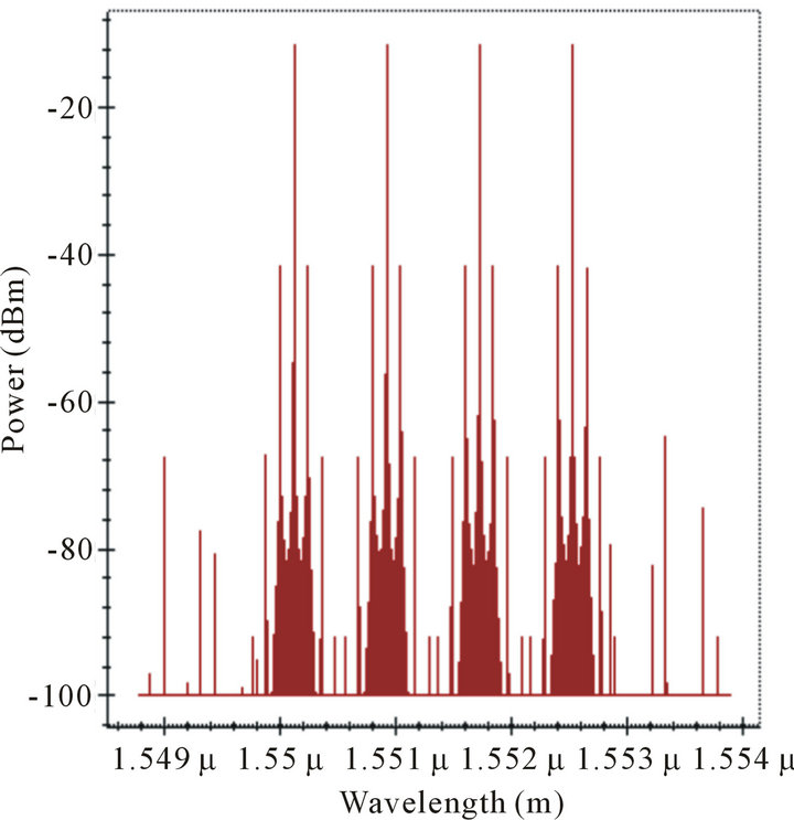
These four subsystems are combined through WDM MUX and transmitted through bidirectional SMF then distributed via splitter to eight ONUs. To compensate dispersion and FWM, DCF and FBGs are used respectively. Design parameters are shown in Table 1. After passing through DCF output power is reduced to 1 dBm, then two FBGs are used. First FBG remove the signals, which are greater than fourth channel wavelength 1552.5 nm and second FBG remove the signals less than first channel wavelength 1550.11 nm. The Output spectrum before FBG (after bidirectional fiber) and then after FBG is shown in Figure 3.
At receiver, WDM DEMUX, PIN photo-detector at 800 GHz sample rate, 0.6 A/W responsivity and 1 nA dark current, band pass Bessel filter at 15 GHz frequency and 2.5 GHz bandwidth and AM demodulator at 15 GHz frequency and 0.9375 GHz cut-off frequency are selected for the electrical transmission. The designing inside ONU1 is shown in Figure 4. For analysis different analyzers are attached at both the transmitter and receiver side. After ONUs, eight subsystems are connected with four 3R regenerators and BER analyzers as shown in Figure 5. Similarly in upstream direction 1300 nm wavelength with 0 dBm power from eight ONUs is combined through combiner and sent via bidirectional fiber to OLT.
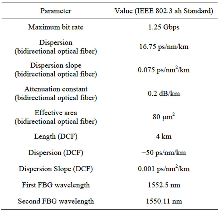
Table 1. Design parameters.
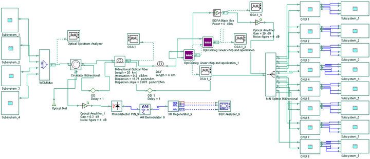
Figure 1. Model for the compensation of dispersion and FWM on WDM-EPON with radio frequency.
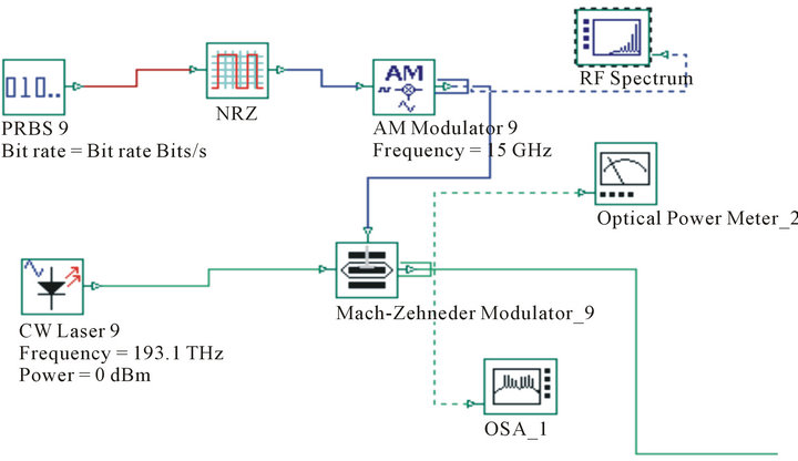
Figure 2. Designing inside first subsystem at the transmitter.
 (a)
(a)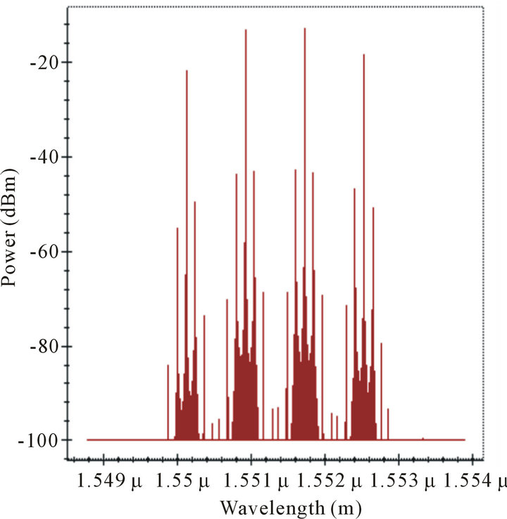 (b)
(b)
Figure 3. Output spectrum (a) Before FBG; (b) After FBG.
3. Results and Discussion
The simulation setup of Figure 2 is employed to compensate dispersion and FWM for WDM RoF-EPON Link. DCF and FBG are used after bidirectional optical fiber for the compensation. DCF provides an optical medium with a relatively large negative chromatic dispersion factor (D(λ)) at the operating wavelength. DCF are more mature, stable and not easily affected by temperature. DCF has become a most useful method of dispersion compensation and has been extensively studied. Similarly FWM can have important deleterious effects in optical fiber communications, particularly in the context of wavelength division multiplexing, where it can cause crosstalk between different wavelength channels, and/or an imbalance of channel powers.
To select the dispersion value for DCF, we have analyzed the output for different dispersions.
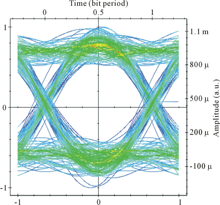
From Figure 6, we are getting maximum Q factor at −50 ps/nm/km dispersion value. Further to compensate FWM, two FBGs at 1550.11 and 1552.5 nm wavelengths are used to remove signals before first and after fourth channel frequency. Eye diagrams are compared at ONUs. BER patterns at ONU1 for Rx1 and Rx4 with and without DCF+ FBG are shown in Figures 7 and 8 respectively.
By comparing the BER patterns of Figures 7 and 8 at Rx1 and Rx4, we analyzed that the eye opening is 77.67% higher with the use of DCF + FBG compensation as compared to without DCF + FBG compensation. Further the results are compared in terms of Q factor for different input power and different optical length as
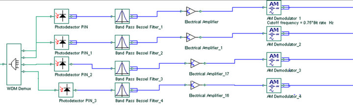

Figure 4. Designing inside ONU1.
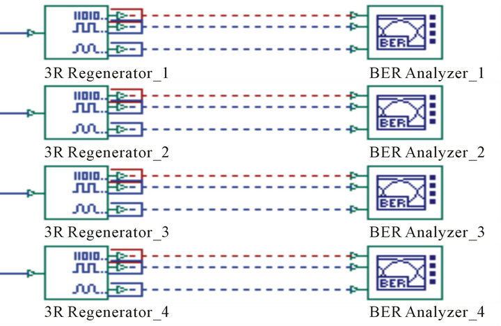
Figure 5. Designing inside first subsystem at Rx1.
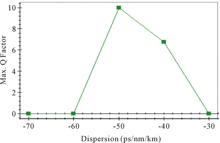
Figure 6. Output for different dispersion values.
shown in Figures 9 and 10.
We analyzed that the performance of the system can be enhanced by compensating dispersion and FWM with the use of DCF and FBG.
4. Conclusion
Four channels, WDM-EPON model with RoF is simulated and analyzed for dispersion and FWM. For the compensation of dispersion and FWM, DCF at −50 ps/nm/km dispersion value and two FBGs at 1550.11 and 1552.5 nm wavelengths are used. The improvement in the performance has been obtained 77.67% in terms of Q factor with and without DCF + FBG. The results are also
 (a)
(a) (b)
(b)
Figure 7. BER at Rx1 (a) Without DCF + FBG; (b) With DCF + FBG.
 (a)
(a)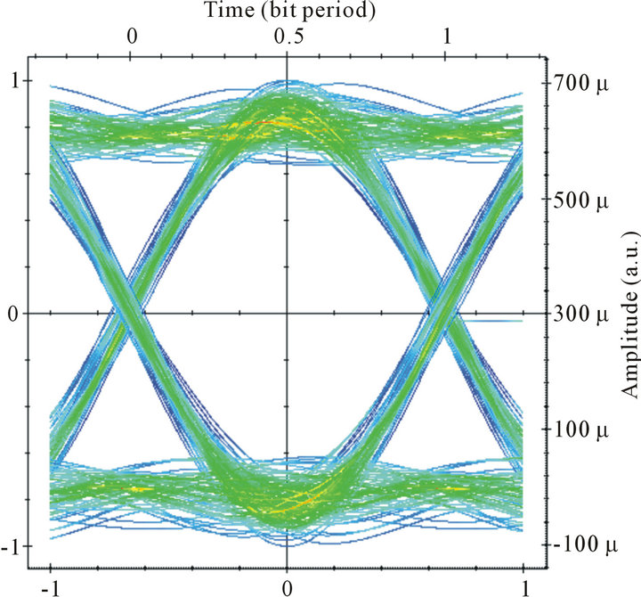 (b)
(b)
Figure 8. BER at Rx4 (a) Without DCF + FBG; (b) With DCF + FBG.
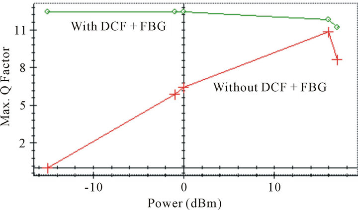
Figure 9. Q factor with and without DCF + FBG for different input power at Rx1.
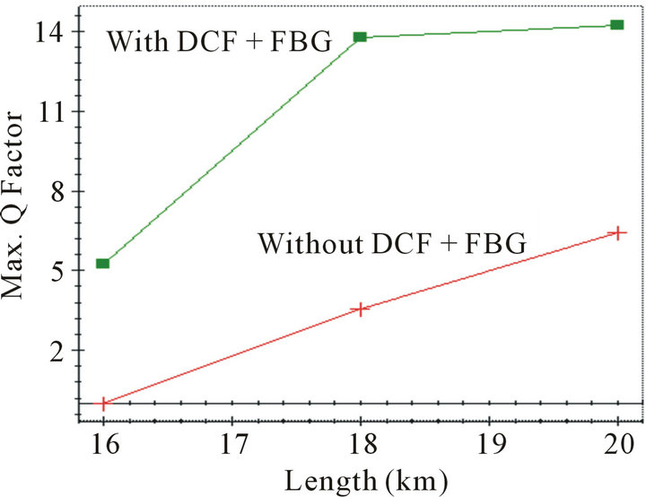
Figure 10. Q factor with and without DCF + FBG for different fiber length at Rx1.
compared for different input power and fiber length, with and without DCF + FBG.
REFERENCES
- R. A. Griffin, P. M. Lane and J. J. O’Reilly, “Radio-overFiber Distribution Using an Optical Millimeter-Wave/ DWDM Overlay,” Optical Fiber Communication Conference, Vol. 2, 1999, pp. 70-72.
- R. A. Griffin, “DWDM Aspects of Radio-over-Fiber,” Lasers and Electro-Optics Society 2000 Annual Meeting, Vol. 1, 2000, pp. 76-77.
- G. K. Chang, J. Yu and Z. Jia, “Architecture and Enabling Technologies for Super Broadband Radio-over-Fiber Optical-Wireless Access Networks,” IEEE International Conference, Victoria, 3-5 October 2007, pp. 24-28.
- W. Chen, S. Y. Li, P. X. Lu, D. X. Wang and W. Y. Luo, “Dispersion Compensation Optical Fiber Modules for 40 Gbps WDM Communication Systems,” Frontiers of Optoelectronics in China, Vol. 3, No. 4, 2010, pp. 333-338. doi:10.1007/s12200-010-0117-6
- G. P. Agrawal, “Nonlinear Fiber Optics,” 2nd Edition, Academic Press, San Diego, 1995.
- M. I. Hayee and A. E. Willner, “Preand Post-Compensation of Dispersion and Linearities in 10-Gb/s WDM,” IEEE Photonics Technology Letters, Vol. 9, No. 9, 1997, pp. 1271-1273.
- C. Caspar, H.-M. Foisel, A. Gladisch, N. Hanik, F. K. Uppers, R. Ludwig, A. Mattheus, W. Pieper, B. Strebel and H. G. Weber, “RZ versus NRZ Modulation Format for Dispersion Compensated SMF-Based 10-Gb/s Transmission with More than 100-km Amplifier Spacing,” IEEE Photonics Technology Letters, Vol. 11, No. 4, 1999, pp. 481-483.
- R. W. Tkach, A. R. Chraplyvy, F. Forghieri, A. H. Gnauch and R. M. Derosier, “Four-Photon Mixing and High-Speed WDM Systems,” Journal of Lightwave Technology, Vol. 13, No. 5, 1995, pp. 842-849. doi:10.1109/50.387800
- N. Shibata, R. P. Braun and R. G. Waarts, “Phase-Mismatch Dependence of Efficiency of Wave Generation through Four-Wave Mixing in a Single-Mode Optical Fiber,” Journal of Quantum Electronics, Vol. 23, No. 7, 1987, pp. 1205-1210. doi:10.1109/JQE.1987.1073489
- V. Kapoor, B. Kaur and A. Sharma, “A Simulation Study on WDM Rof-EPON Link in the Presence of Four-Wave Mixing,” International Academic Conference, Las Vegas, October 2011, pp. 259-264.
- B. Xiang, “Application of Fiber Grating (FG) in Modern Optical Communications and Beyond,” International Journal of Advances in Optical Communication and Networks, Vol. 1, No. 1, 2010, pp. 17-22.
- Z. Pan, Y. Xie, S. Lee and A. E. Willner, “Tunable Compensation for Polarization-Mode Dispersion Using a Birefringent Nonlinearly-Chirped Bragg Grating in a DualPass Configuration,” US Patent 6400869, 2002.
- X. Kun, F. Jia, X. Chen, M. Jin, M. Chen, X. Li and S. Xie, “A Novel Adjustable PMD Compensation Using Sampled Bragg Gratings with Uniform Grating Period,” Optics Communications, Vol. 202, No. 4-6, 2002, pp. 297- 302. doi:10.1016/S0030-4018(02)01111-2
- V. Kumar, B. Kaur and A. K. Sharma, “A Comparative Analysis of WDM RoF-EPON Link with and without DCF,” International Conference (ICMEME 2012), Bangkok, 17-18 March 2012, pp. 31-34.
- “IEEE P802.3 ah Task Force,” 2004. http://www.ieee802.org/3/efm