Engineering
Vol. 2 No. 11 (2010) , Article ID: 3166 , 4 pages DOI:10.4236/eng.2010.211110
A Three-Axis Robot Using a Remote Network Control System
1Department of Automatic Control Engineering, Chungchou Institute of Technology, Changhua, Taiwan, China
2Department of Information Management, Yu Da University, Miaoli, Taiwan, China
E-mail: tslan888@yahoo.com.tw
Received August 7, 2010; revised October 8, 2010; accepted October 18, 2010
Keywords: Three-Axis Robot, Remote Network Monitoring
ABSTRACT
For the petroleum industry, to reduce the risk of a gas explosion in dangerous working areas, the use of explosion-proof equipment such as air-driven devices which are free from explosions becomes essential. Moreover, for the purpose of saving manpower, a remote operation using a robot via a visual monitoring system and a network is used. However, to overcome the drawback of costly manpower and to improve safety in explo-sion-prone zones, a three-axis robot using a remote network control system is proposed. In this paper, the three-axis robot can be monitored online via the USB protocol. Furth-ermore, it also can be remotely manipulated via the TCP/IP protocol by clicking the command of the VB interface on the client pc. Consequently, the remote-control three-axis robot can not only work for people in severe and dangerous circumstances but also can reduce the cost of manpower.
1. Introduction
As new trends in the modern world evolve, robots begin to make their presence felt. In order to improve the process and reduce unnecessary manpower, various industrial robots have been widely developed [1]. Traditional robot driven by electrical motor used in a dangerous explosion zone has been prohibited. To overcome the drawback, a new design of explosion proof for an electrical motor is required [2]. However, it is extremely expensive. Therefore, to avoid explosions caused by sparks in the petroleum industry, an air-driven device which is explosion free is necessary [3,4]. Currently, various robots have been presented; however, they lack remote interactivity between the robot and the user. In order to manually operate a robot to execute a specific job in a dangerous working area, a remote-control robot system driven by air is vital. In this paper, the three-axis robot equipped with a web camera, which can be monitored online via the USB protocol, is established. Obviously, the remote-control three-axis robot not only can work for people in volatile and dangerous circumstances but also can lower the cost of manpower. Consequently, a PC-based control system is constructed using a VB interface in both a sever pc and a client pc via the RS232/RS485 protocol.
2. A PC-Based Remote Controlling System
Automation systems used in industrial processing to reduce manpower are seen everywhere. As indicated in Figure 1, a remote three-axis robot system using two VB interfaces (one in the sever pc and the other in the client pc) via a network and a web camera has been established.
As indicated in Figure 2, two kinds of system modulus (7060D and 7520) are applied in the remote monitoring/control system. Because of the serious decay of the signal for a RS232 protocol traveling over a distance of fifteen meters, a new protocol (RS485) in which the effect of signal decay is trivial for long-distance transportation is recommended [5,6]. Here, the 7520 module is a protocol transfer device from RS232 to RS 485 [7,8]. A command emitted from the sever pc will be sent to other modulus via the RS232/RS485 converter.
The hardware of the electromagnetic control valve shown in Figure 3 is used to manipulate the piston motion (i.e., the motion of the robotic arm) using a 7060D module’s DI/O (digital input and output) that is emitted from a sever pc via a 7520A module (a protocol trans-
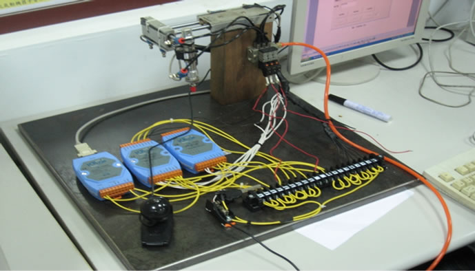
Figure 1. A remote three-axis robot system.
lator from RS232 to RS285). As indicated in Figure 4, the electromagnetic control valve will be triggered by the digital output signal of the 7060 module via a RS232/RS485 protocol using a VB interface on the sever
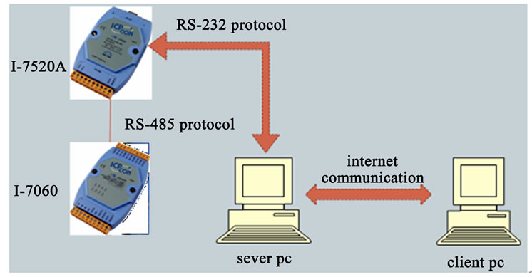
Figure 2. Two kinds of modulus.
pc. The status of the piston positions will be also detected by the digital input signal of the 7060 module transmitted from the magnetic signals (a0, a1, b0, b1, c0, and c1) of the pistons.
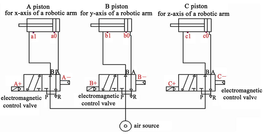
Figure 3. The diagram of the pistons with respect to three electroma-gnetic control valves.
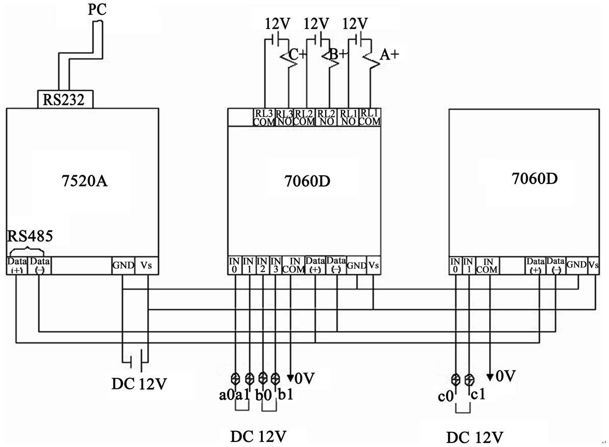
Figure 4. The wire connections of the modulus.
As indicated in Figures 5 and 6, the user can manipulate the robot’s arm by clicking the movement button to actuate the related electromagnetic control valve via the VB dialogue on both the pc sever and the pc client. Moreover, the current position of pistons A, B, and C will be monitored by the lights of A+, A–, B+, B–, C+, and C– in the VB dialogues in pc server and client.
Before the gas robotic arm is performed, the system confirmation is carried based on a system testing diagram. As indicated in Figure 7, the signals of three electromagnetic control valves will be rechecked during the manipulating process. Besides, the related piston triggered by clicking the command button in the VB dialogue will also be responded to the lights of A+, A–, B+, B–, C+, and C– in pc’s interface.
To monitor the real motion of robotic arm online, a web camera is installed. The image of the robotic arm will be caught and sent back to the sever pc via a USB protocol. Moreover, the image will be transmitted to the client pc via the TCP/IP protocol.
3. Results and Discussion
3.1. Results
As indicated in Figures 5 and 6, the remote control of a three-axis robot using two VB interfaces (one in the sever pc and the other in the client pc) via a network and a web camera has been established successfully. Before the client pc can be manipulated, based on the TCP/IP protocol, the sever pc shall be connected first by inputting the IP address and transport number in the client’s pc dialogue. To keep the robotic arm in a specific motion, six buttons (x-axis forward, x-axis backward, y-axis forwarding, y-axis backward, z-axis forward, and z-axis backward,) of the robot’s motion will be selected on the VB dialogue of the sever pc.
3.2. Discussion
The user can manipulate the robotic arm in both the pc
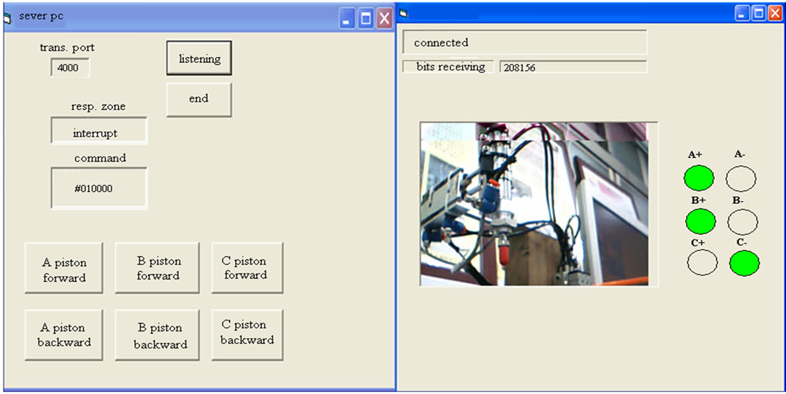
Figure 5. The manual movement of the robot’s arm on the VB dialogue (pc sever).
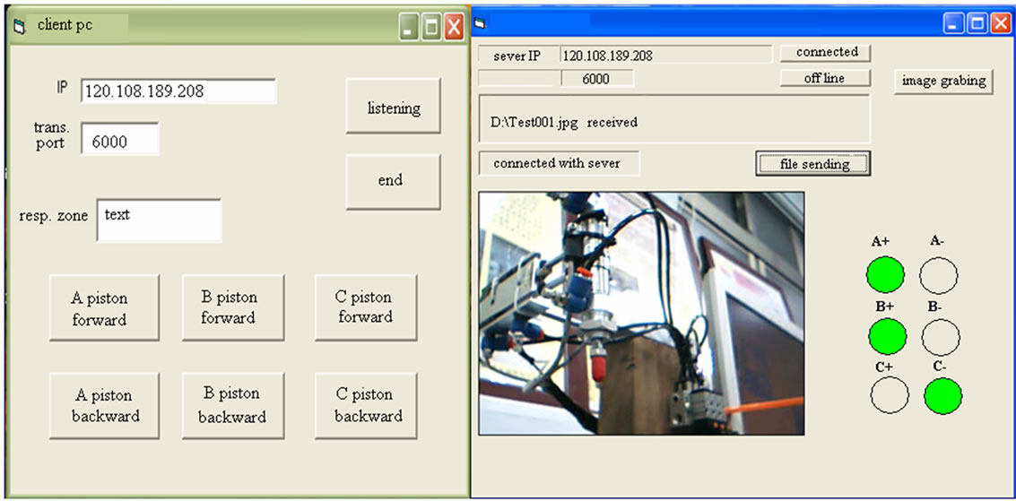
Figure 6. The manual movement of the robot’s arm on the VB dialogue (pc client).
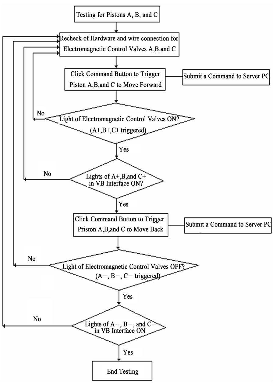
Figure 7. A system testing diagram for a remote-controlled three-axis robotic arm.
sever and the pc client. The status of the robotic arm (the electromagnetic signal of the piston’s location) shown in the VB interface will be transmitted to the pc client via a TCP/IP protocol. The command clicked in the pc client will be also transmitted to the pc sever to actuate the electromagnetic control valve so as to control the piston motion of the piston by switching the air path. Meanwhile, the signals of pistons’ position will be translated as the lights of A+, A–, B+, B–, C+, and C– shown in two VB dialogues in pc server and client. Moreover, the image of the robotic arm will be caught and sent to the pc sever using the USB protocol. The image will be then transmitted from the pc sever to the pc client via the TCP/IP.
4. Conclusions
It has been shown that a remote control system dealing with an air-driven three-axis robotic arm reduces manpower, avoids the explosion, and improves the industrial process. Traditional robot driven by electrical motor used in a dangerous explosion zone has been prohibited. Moreover, an alternative design of explosion proof for an electrical motor is expensive. Therefore, in order to save manpower, avoid the danger for explosion simultaneously, and to cost down the fee of machine, an air-driven robotic arm is compulsory. The air-driven robot provides no spark in the chemical process and can be safely and remotely manipulated using a VB dialogue to trigger an air-driven piston, which is actuated by an electromagnetic control valve via the RS232/RS485. Additionally, a visual monitoring of the robotic arm is performed by transmitting the image of the robotic motion to the sever pc via the USB protocol. Moreover, the image of the robotic motion will be forwarded to the client pc via the TCP/IP protocol. The user at the client pc can also manipulate the robotic motion using a VB interface at the client pc via the TCP/IP protocol.
Consequently, it is noted that both the safety of workers/plant and the efficiency of the industrial process will be improved if an air-driven robotic arm in conjunction with a remote network monitoring/control system is applied when operating in a dangerous work environment.
5. Acknowledgements
The authors acknowledge the financial support of the Project (CCUT-AI-96-AC02). The author would like to thank the anonymous referees who kindly provided the suggestions and comments to improve this work.
6. REFERENCES
- M. C. Chiu, L. J. Yeh and Y. C. Lin, “The Design and Application of a Robotic Vacuum Cleaner,” Journal of Information & Optimization Sciences, Vol. 30, No. 1, 2009, pp. 39-62.
- H. A. Akeel and A. J. Malarz, “Electric Robot for Use in a Hazardous Location,” United States Patent 4984745, 2002.
- Users’ Guidebook for Explosion Protection Electric Facility, Guildline, RIIS-TR-94-2, National Institute of Industrial Safety, 1994.
- M.-R. Lin and C.-Y. Chen, “Applications of Inherently Safer Design on Industrial Processes,” Chemical Engineering, Vol. 47, No. 1, 2000, pp. 41-51.
- M. C. Chiu, “An Automatic Thermal Control on Greenhouse Using Network Remote Controlling System,” Journal of Applied Sciences, Vol. 10, No. 17, 2010, pp. 1944-1950.
- M. C. Chiu, “A Multi-Function Aquarium Equipped with Automatic Thermal Control/Fodder-Feeding/Water Treatment Using Network Remote Controlling System,” Information Technology Journal, Vol. 9, No. 7, 2010, pp. 1458-1466.
- M. C. Chiu, “The Study of Remote Network Monitoring and Controlling System on Thermal Procedure,” in: Y.-L. Chang-Hwa and C.-H. Chai-Ialley, Eds., The Proceedings of 2008 Academic Joint Venture, 2008.
- M. C. Chiu, H. C. Cheng and M. J. Hsu, “The Study of Remote Network Monitoring and Controlling System on Gas-Driven Robotic,” The Proceedings of Mechanics, Light, and Electricity, San-Johns Technical University, Taipei, 2008.