 Journal of Power and Energy Engineering, 2014, 2, 191-200 Published Online September 2014 in SciRes. http://www.scirp.org/journal/jpee http://dx.doi.org/10.4236/jpee.2014.29027 How to cite this paper: Tan, J.C., Zhang, S.X., Mo, J., Xiong, X.P., Liao, B.L. and Zhang, C. (2014) Dynamic Testing of an IEC 61850 Based 110 kV Smart Substation Solution. Journal of Power and Energy Engineering, 2, 191-200. http://dx.doi.org/10.4236/jpee.2014.29027 Dynamic Testing of an IEC 61850 Based 110 kV Smart Substation Solution Jiancheng Tan, Shuxian Zhang, Jun Mo, Xiaoping Xiong, Bilian Liao, Chao Zhang Smart Substation Technologies and Applications Lab, Guangxi University, Nanning China Email: jctan@gxu.edu.cn, mojin1232@sina.com, xxp001@sina.com, lbsjx519@163.com Received August 2014 Abstract This paper presents the dynamic simulation and testing to verify the smart substation solutions designed for a brown field 110 kV retrofitting project. An IEC 61850 based aotomation design, transitioning the conventional substation into a smart substation, where existing current/voltage transformers remain in service, and smart Field Apparatus Interface Units (FAIUs) are utilised to bridge the conventional primary system to the IEC 61850 based secondary system. While outdoor switchgears and field instrument transformers are equipped with FAIUs, MV indoor switchgears are installed with IEDs mounted on the top. Direct point-to-point connections serve as process buses, and a single PRP/RSTP LAN is employed at station bus level. Extensive dynamic simulation and testing were conducted in the Smart Substation Technologies Lab, and test results show the smart substation performance meets and exceeds the substation reliability requirement. Keywords Process Bus, Station Bus, GOOSE, Digital Substations, Smart Substations, Parallel Redudancy 1. Introduction At present, China is undergoing the development of a large-scale strong solid power grid. The complexities of power systems associated with various operational modes, demands smart and intelligent apparatus, and more efficient information exchange at all levels. New substations should be built in a new way, in order to facilitate easy engineering, shorten installation and commissioning time, and be capable of performing incremental up- grades in the future in a flexible and robust way. The new national-wide initiative for smart substations aims at tapping to the latest technology available for innovative solutions [1] [2]. The global standard IEC 61850 facilitates seamless information exchange between apparatus and the network based secondary system. Moving towards an information highway for protection, control, automation and beyond, opens up a world of opportunities in engineering, construction, commissioning, operation and maintenance. With the ample proof of its significant savings incurred in thousands projects world-wide [3]-[5], IEC 61850 based smart substation solutions are proven to be viable and cost effective [6]-[8]. This paper investigates an IEC 61850 related smart substation solution, where intelligent field interface units (FAIUs) are employed to transfer conventional current/voltage transformers and outdoor switchgears into smart 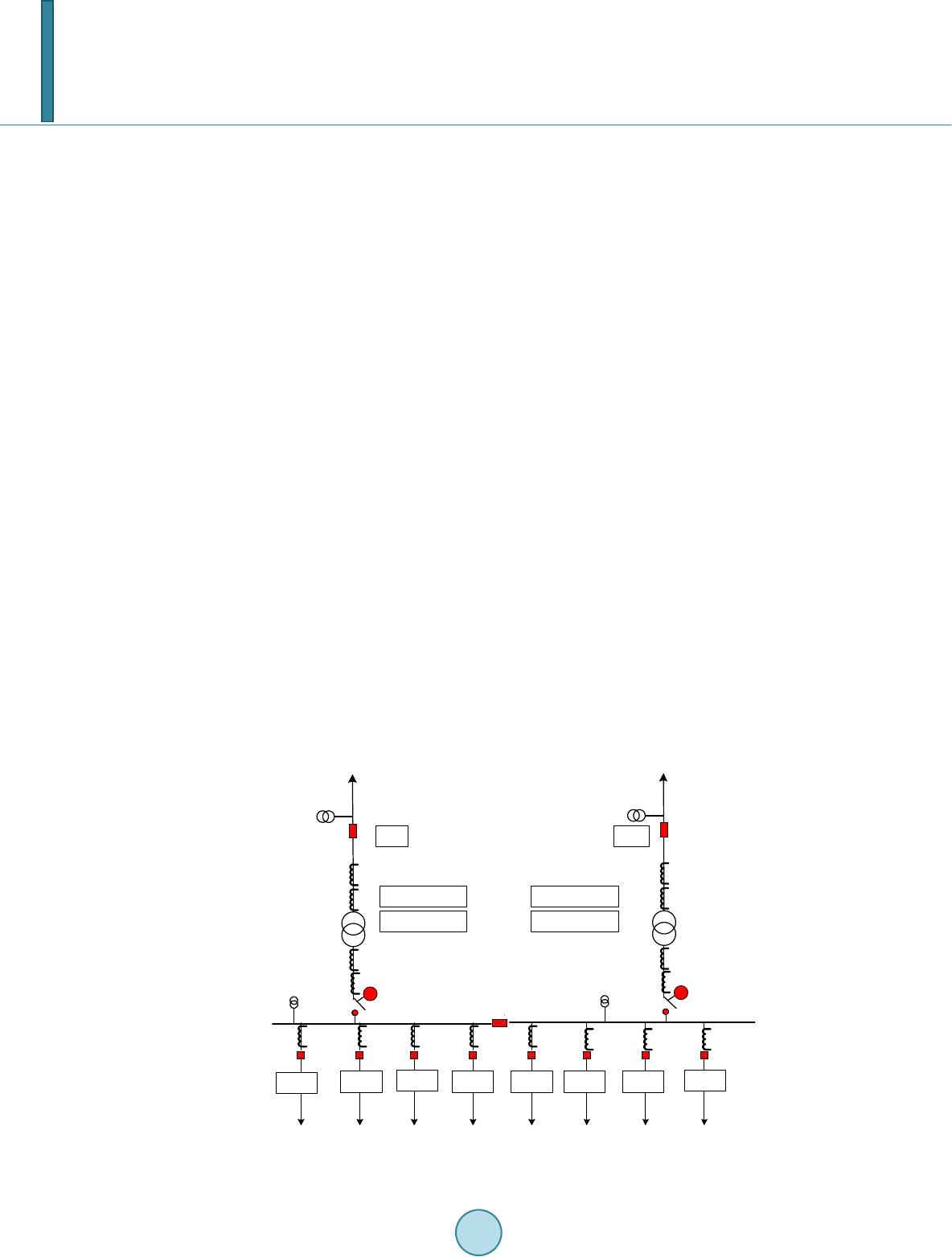 J. C. Tan et al. apparatus. The FAIUs are of merging unit modules, integrated with RTU and communication functions, which acquires the analog current and voltage signals, digitizes them into IEC 61850-9-2LE sampled value streams, and transmits them over the dedicated point-to-point connected process buses. The field apparatus interface units (FAIUs) are of rugged modular design, configurable Sampled Value (SV) and GOOSE datasets, supports up to eight 100mbps FX ports, thus are flexible, robust and versatile for field deployment. At the station bus level, a single substation LAN is designed for protection signaling, SCADA control and remote access, where parallel redundancy protocol (PRP) and rapid spinning tree protocol (RSTP) are used to ensure reliable data transmission with guaranteed delivery of mission critical and time stringent protection signals. The 110 kV/10 kV smart substation demonstrates the use of FAIUs for sampled value streams over the pro- posed process bus, and for GOOSE applications over the substation LANs. A complete secondary system is constructed in the Smart Substation Technologies Lab, Guangxi University, where Real Time Digital Simulator (RTDS) is used to model the primary system of the substation equipment. Current and voltage signals from the relaying points from RTDS are amplified to the true secondary level and injected onto the FAIUs and relays under testing, with statuses of indoor and outdoor switchgears from the RTDS hard wired to the FAIUs and relays. Decisions from the secondary system, i.e. either the FAIUs or relays are fed back to the RTDS, and the late con- tinues simulating the power system in real time until it reaches a new steady state or have lost stability. A RTDS batch test program for automatic testing and recoding is developed in the lab, which repeats the same test for a pre-set 100 times. While during the tests, a traffic generation device hosted in the engineering station generates network traffics and injects them into the station bus LAN, to flood the substation communication infrastructure. Test results were plotted to verify the proposed solutions under various background traffic conditions. Extensive tests were conducted in the lab. Analyzing the recorded test results, no package drops were observed. Sampled value streams and GOOSE tripping over the LAN is proven to be fast, reliable and not affected by the background traffic over the proposed substation LAN, where dedicated point-to-point connections are utilized at process bus level, which contain the process bus traffic into where absolutely required, and a single PRP/RSTP LAN for multicasting GOOSE messages, SCADA applications and remote access etc, and is proven to be robust and reliable. 2. Overview of 110 kV/10 kV Substations The 110 kV/10 kV substation is of eight indoor switchgear feeders connected onto two separated busbars. The two bus sections are connected via a normally closed bus sectionaliser. A transfer bus with a bus coupler dedi- cated for maintenance related tasks is installed but not shown in Figure 1. While the 10 kV indoor switchgear F1_50A F2_50A F3_50A F4_50A F5_50AF6_50A F7_50AF8_50A 10 kV Bus2 T1 110 kV L1 Bus1 T1_87A/Bus1_50A T1_87B/Bus1_50B PT_ L1 M PT_Bus1 T2 110 kV L2 T2_87A/Bus2_50A T2_87B/Bus2_50B PT_ L2 M PT_Bus2 50BF1 50BF2 Figure 1. 110 kV/1 0 kV substation arrangement.  J. C. Tan et al. system is within the control building, the 110 kV lines and transformers are outdoor in the switchyard. Each 10 kV bus section is supplied by a 110 kV/10 kV, 25 MVA transformer with a two (2) cycle breaker on the HV side. There is no circuit breaker but a motor driven disconnect switch at the 10 kV side. Distributed generations (DGs) are tapped onto the 10kV feeders. As observed in Figure 1, if a fault occurs on T1, or on Bus1, fault isolation requires tripping the associated HV breaker, the bus sectionaliser, and all feeder breakers connected on Bus 1. Thus, integrated dual redundant transformer and bus protection schemes are ap- plied, and each 110 kV breaker failure protection is a standalone single breaker failure (50BF) relay hard wired from all digital and non-didgital relays tripping the breaker. Upon detection of a breaker failure, the 50BF will initiate the trip to all electrically connected breakers, as well issue direct transfer trip (DTT) signals to the re- mote substations where lines are directly connected with the fauty breaker. No 110kV line protection is applied in this case. 2.1. 10 kV Feeder Protection A feeder relay provides feeder protection and the associated controls, is configured to receive GOOSE trip sig- nals from the 110 kV 50BF relay and the transformer/bus relays to trip the feeder breaker upon a breaker failure, transformer or bus fault. The feeder relay will issue a GOOSE signal to the associated bus relay upon detection of a fault, a motor start up or load encroachment condition. The feeder relay will also issue a GOOSE trip to the Bus relay if a breaker failure condition is detected. The following GOOSE publications are applied • Feeder fault GOOSE Blocking; • Feeder downstream motor start-up GOOSE Blocking; • Feeder load encroachments GOOSE Blocking; • Feeder breaker failure Bus GOOSE Trip. 2.2. 10 kV Bus Protection Medium Voltage Switchgear 10kV Bus protection is designed with a fast bus protection scheme, and a coordi- nated time overcurrent scheme in parallel. The bus relay trip decision is delayed for a pre-set four (4) cycle de- lay in the fast bus scheme, and a minimum 300ms delay time in the coordinated overcurrent scheme. The fast bus protection scheme was a hard wired approach, simple in principle, easy to expand, but requires information exchange between multiple devices. The complicated hard-wiring is error-prone, and tremendously increases the installation and maintenance costs. In this application, wiring between the bus and other relays are removed, and GOOSE messages are employed, with the blocking time delay reduced to two (2) cycles. Upon a Bus fault, a GOOSE BF Initiation will be issued to the 50BF relay, and reclose of the feeder breaker is prohibited. While the hard wired solution requires two seperated connections, a single multicasting GOOSE Bus Trip signal is suffi- cient to serve all. The following GOOSE messages are configured to receive: • Feeder 1 Fault/Start-up/Load Encroachment GOOSE Blocking; • Feeder 2 Fault/Start-up/Load Encroachment GOOSE Blocking; • Feeder 3 Fault/Start-up/Load Encroachment GOOSE Blocking; • Feeder 4 Fault/Start-up/Load Encroachment GOOSE Blocking; • Feeder 1 Breaker failure GOOSE Bus Trip; • Feeder 2 Breaker failure GOOSE Bus Trip; • Feeder 3 Breaker failure GOOSE Bus Trip; • Feeder 4 Breaker failure GOOSE Bus Trip. 2.3. Transformer Protection Protection of the 110 kV/10 kV transformers is provided by dual differential schemes. Upon detection of a transformer fault, a GOOSE BF initiation signal is issued, and cancel reclose GOOSE message is send to pre- vent the breaker being reclosed. The following GOOSE messages will be published: • Transformer fault GOOSE BF Initiation; • Transformer fault GOOSE cancel recluse;  J. C. Tan et al. 2.4. 50BF Protection The breaker failure 50BF relay will issue GOOSE BF trips to open the 10 kV feeder breakers upon detection of a breaker failure condition, as well sends direct transfer trip signals to the remote line ends relays. The 50BF re- lay receives the following BF initiation signals from digital relays: • Transformer/Bus A relay GOOSE BF Initiation; • Transformer/Bus B relay GOOSE BF Initiation; • Non-digital relay hard wired Initiation. All digital relays are configured to receive the associated switchgear GOOSE status messages, and report to the Gateway/HMI for SCADA applications. Station wide controls are implemented using the HMI single line diagram graphic interface. For outdoor switchgears, field apparatus interface units/boxes (FAIUs) are used to transfer the conventional current and voltage transformers and circuit breakers into smart apparatus. 3. Field Apparatus interface Units The field apparatus interface unit (FAIU) serves as the interface units between primary systems in the switch- yard and secondary systems in the control building. As illustrated in Figure 2, the FAIU units are equipment with two analog modules, hard wired to conventional current and voltage transformers, as well switchgears such as breakers and disconnect switches in the switchyard. Connections to the secondary IEDs in the control build- ing are via optical fiber connections. The functional modules of the FAIUs are as below: 3.1. Merging Unit Functions A merging unit module may equip two analog modules, acquires analog current and voltage signals, and digi- tizes them into maximum 4 sets of sampled value streams according to IEC 61850-9-2LE. Each set of the sam- pled value streams is configurable with (4I, 4V) or (4I, 4I) signals, and is independently assigned with the com- munication ports specified. The following analog modules are available in a FAIU: • 4I (5A), 4V; • 4I (1A), 4V; • 8I (5A); • 8I (1A). IO Module 16I , 24O A/D Conversions / Data Processing IEC 61850-9-2-LE Merging Unit Module RTU Module Analog Module 1 4I, 4V Analog Module 1 4I, 4V Analog Module 1 4I, 4V Analog Module 2 8I Data Processing IEC 61850-8-1 A/D Conversions / Data Processing IEC 61850-9-2-LE Communication Module 1 100mbps, FX, PRP/RSTP, HSR Communication Module 2 100mbps, FX, PRP/RSTP, HSR Port1 Port2 Port3 Port4Port5 Port6 Port7 Port8 Figure 2. Field interface unit t.  J. C. Tan et al. 3.2. Remote Terminal Unit Functions A Remote Terminal Unit module interfaces with switchyard circuit breakers and disconnect switches, is of the bay control unit function. It acquires the breaker status, processes them as various GOOSE data sets according to IEC 61850-8-1 and publish tem onto the station bus LAN. Each GOOSE data sets can be configured individu- ally and can be assigned to specific ports. 3.3. Communication Module Each communication module is of 4 ports, each port is capable of transmitting the assigned sampled value streams, and/or combined with GOOSE message transmission, as well receiving GOOSE messages, support PRP, HSR and/or RSTP redundancy protocols. The configurable field interface units (FAIUs) are robust, flexible and scalable, serve as key elements in green field substations installed with conventional CTs/PTs, or for substation retrofitting solutions, where conven- tional apparatus installed have an average life cycle of 60 years. 4. Substation Architecture The reliability of the substation architecture is vital to the acceptance of the industry. This is particularly true to field deployment when time stringent and mission critical protection signals such as sampled values and trip signals come to play. The reliability of the process bus system not only depends on the merging units and the process bus relays utilised, the process bus architecture and the associated redundancy protocols supported by the LAN and the IEDs, will also have significant impact, as well the volume of traffic and their related priority levels while transmitting on the network. 4.1. Process Bus Considering an IEC61850-9-2LE sampled value data stream consuming approximate 5mbps bandwidth, at sys- tem frequency 50Hz and the defined sampling rate of 80 samples per cycle, process bus traffic is of high volume in nature, and consistent all time, thus must be carefully engineered at the process bus level, and bridge to where absolutely needed, and provide means of isolation from the mission critical and time stringent protection trip- ping signals. Table 1 illustrates the detailed current and voltage configuration and assignments. In this application, dual redundant field interface units are employed for the transformer/bus protection schemes. Six (6) process bus re- lays and four (4) field interface units are designated for process bus applications. The protection relays include: • T1_87A/Bus1_50A • T1_87B/Bus1_50B • 50BF1 • T2_87A/Bus2_50A • T2_87B/Bus2_50B • 50BF2 The field interface units are hard wired to acquire the current and voltage signals, as well the status informa- tion circuit breakers and disconnect switches, and are of the following modules: • Module 1: Merging Unit module; • Module 2: RTU module; • Module 3: Communication module. Where, the Merging Unit module consists of two (2) 4I, 4V analog modules, and the copper connections with the current, voltage transformers and outdoor switchgears are as described in Figure 3. The field interface unit is configured to transmit various sampled value streams for specific protection appli- cations. A transformer/bus relay will receive sampled values from one single field interface unit, information received include:  J. C. Tan et al. Table 1. IEC 61850-9-2le sampled value datasets assignments. SV Dataset 4 I 4 V SVT1_11 CT_T1H1A CT_T1H1B CT_T1H1C CT_T1H1G PT_L1A PT_L1B PT_ L1C PT_L1G SVT1_12 CT_T1L1A CT_T1L1B CT_T1L1C CT_T1L1G PT_Bus1A PT_Bus1B PT_Bus1C PT_Bus1G SVT1_21 CT_T1H2A CT_T1H2B CT_T1H2C CT_T1H2G PT_L1A PT_L1B PT_ L1C PT_L1G SVT1_22 CT_T1L2A CT_T1L2B CT_T1L2C CT_T1L2G PT_Bus1A PT_Bus1B PT_Bus1C PT_Bus1G SVT2_11 CT_T2H1A CT_T2H1B CT_T2H1C CT_T2H1G PT_L2A PT_L2B PT_ L2C PT_L2G SVT2_12 CT_T2L1A CT_T2L1B CT_T2L1C CT_T2L1G PT_Bus2A PT_Bus2B PT_Bus2C PT_Bus2G SVT2_21 CT_T2H2A CT_T2H2B CT_T2H2C CT_T2H2G PT_L2A PT_L2B PT_ L2C PT_L2G SVT2_22 CT_T2L2A CT_T2L2B CT_T2L2C CT_T2L2G PT_Bus2A PT_Bus2B PT_Bus2C PT_Bus2G F1_50A F2_50A F3_50A F4_50A 10 kV T1 FAIB_T1A FAIB_T1B 110 kV L1 Bus1 T1_87A/Bus1_50A T1_87B/Bus1_50B PT_ L1 M PT_Bus1 To Station Bus To Station Bus GOOSE Process Bus 50BF1 Process Bus Figure 3. Process bus (partial). • Four (4) Currents from transformer HV bushing CT; • Four (4) Currents from transformer LV bushing CT; • Four (4) Voltages from 110 kV Line PT; • Four (4) Voltages from 10 kV Bus PT. As demonstrated in Table 2, a field interface unit also supplies current and voltage signals to the breaker fail- ure relay. No redundancy is required for standalone breaker failure protection. Data transmitted over a process bus is mission critical. In this application, point-to-point fiber connections from field interface units (FAIUs) to relays are utilized as process bus architecture, this contains process bus traffic to where it is absolutely required. This simple architecture design ensures short latency delay, prevents traffic flooding the LAN. It is simple, robust, easy to maintain, and reliable to operate. The scalability and ex- pandability of the overall substation process bus applications are inherently achieved by the field interface units deployment strategies, thus are flexible, robust and versatile for all substation configurations. 4.2. Station Bus Previous applications for station bus architecture design utilizes rugged Ethernet switches and rapid spanning tree protocol (RSTP) as self-healing redundancy mechanism. While it is proven to be viable with many indus- trial applications, it is doubtful that reliability of the Protection/SCADA system may subject to issues, and there  J. C. Tan et al. is possibility reliability of the system may decline due to complicated routing algorithms and configurations, which in return may probes more human error during engineering and maintenance stages. 1) Ethernet Switch Two substation grade Ethernet switches are installed to form up the parallel redundancy network for station bus, each with 24 × 100 mbps FX ports, 4 × RJ45 100/1000 mbps ports for maintenance and engineering access. 2) Parallel Redundancy Protocol All IEDs and FAIUs in the secondary system supports PRP/RSTP redundancy, this gurantees no GOOSE messsage drops, for network architecture design as depicted in Figure 4. 3) VLAN and Priority Tagging No VLANs are applied. VLAN ID is set to zero. Priority mapping between IEC 61850 and Ethernet Switch hardware related priority forward is given in Figure 5. 4) Message Priority Assignments All GOOSE messages transmitted over the station bus LAN are with priority tagging, and are transmitted over the LAN, potentially available to all IED connected. The priority of GOOSE message assignments are based on the signal missions inherited, and are listed in Table 3. All GOOSE messages transmitted over the Station LAN are priority tagged. Other traffic such as SCADA MMS alarms, remote access, file transfers etc. are dealt with best effort. The Station Bus LAN employs PRP/RSTP redundancy, requires all IEDs connected support the PRP protocol. Minimum switch configuration is required, simple, easy and straightforward. 5. Solution Evaluation A fully functional secondary system with all protective relays, substation Gateway to SCADA, and HMI for alarm processing and station wide control of the 110 kV/10 kV substation as depicted in Figure 1 has been de- veloped and constructed in the Smart Substation Technology LAB of Guangxi University. The real time digital simulator (RTDS) models the detailed apparatus including the two 110 kV transmission lines transformers, circuit breakers, current and voltage transformers etc. in the 110 kV/10 kV substation, and grid beyond the two 110 kV lines are modeled using simplified grid models and equivalent sources at both ends. Table 2. Field interface units assignments. Protection SV1 SV2 FAIU T1_87A/Bus1_50A SVT1_11 SVT1_12 FAIU_T1A T1_87B/Bus1_50B SVT1_21 SVT1_22 FAIU_T1B 50BF1 SVT1_21 FAIU_T1B T2_87A/Bus2_50A SVT2_11 SVT2_12 FAIU_T2A T2_87B/Bus2_50B SVT2_21 SVT2_22 FAIU_T2B 50BF2 SVT2_21 FAIU_T2B F1_50A F2_50A F7_50A F8_50AF8_50A T1_87A/Bus1_50A T1_87B/Bus1_50B FAIB_T1A FAIB_T1B T2_87A/Bus2_50A T2_87B/Bus2_50B FAIB_T2A FAIB_T2B PRP/RSTP LAN1PRP/RSTP LAN2 Field Apparatus Interface Units Field Apparatus Interface Units Process Buses Control Building, Station Bus HMI GatewayEngineering Station Remote Access Process Buses 50BF2 50BF1 GPS Figure 4. Substation LAN Architecture.  J. C. Tan et al. IEC 61850 Priority Mapping 7 → 4 6 → 4 5 → 3 4 → 3 3 → 2 2 → 2 1 → 1 0 → 1 Figure 5. Priority mapping between IEC 61850 and Ethernet Switches. FAIB_T1B BF 1 F1_50A T2_87A/ Bus2_50A T2_87B/ Bus2_50B F5_50A Station Bus (PRP/RSTP LAN) T1_87A/ Bus1_50A T1_87B/ Bus1_50B Current/Voltage Amplifier Current/Voltage Amplifier Current/Voltage Amplifier Gateway HMI F4_50A FAIB_T1A FAIB_T2B FAIB_T2A BF 1 F8_50A GPS R e a l T i m e D i g i t a l S i m u l ( R T D S ) Analog I/V Digital IO/Command Process Bus Traffic Generator Figure 6. RTDS test setup. Table 3. Message priority assignments. Message Priority Tripping 7 BF Tripping 7 BF Initiation 7 Reclose Initiation 5 Reclose Blocking 5 Open/Close 5 Switchgear Status 3 Alarm 3 Other Network Traffic Best effort  J. C. Tan et al. The RTDS simulates the power system normal and fault conditions. Currents and voltage signals at the relay- ing points are outputted to the amplifiers, which are scaled to the true secondary level and injected on the field apparatus interface units (FAIUs) and indoor switchgear protective relays under testing, and the responses from the feeder relays and field interface units (RAIBs) are fed back into the RTDS, which open/trip the circuit breakers in real time, while the simulation continues, until the power system under study reached a new steady state operational point, then starts the next round simulation. The RTDS dynamic simulation and testing con- figuration is given in Figure 6, and a RTDS batch test program is developed which enables the test to be re- peated as pre-defined. A RTDS batch test program is developed which enables the test to be repeated as pre-defined. A total one hundred (100) tests are configured to verify the performance of the proposed smart sub- station solutions under various background traffic conditions. A traffic simulation software developed by the university is hosted in the engineering station, which generates the pre-configured multicasting/unicasting traffic and injects onto the station bus PRP/RSTP LAN, where the secondary system under testing. The multicasting traffic is set with various priority tags, and is intended to flood the LAN under test. Figure 7 demonstrates the trip times recorded for a Bus1 A-G fault with 0.01Ω fault resistance. The back- ground traffic injected onto the station bus LAN under each test is given in Table 4. Analyzing the above test results recorded, the following are observed: 1) Bus 1 relays detect the A-G fault in 12 ms - 20 ms, with the first relay decision time recoded, and the sec- ond discarded. Trip Time Recorded Bus 1 A-G Solid Fault No. of Tests Figure 7. Trip times recorded for 100 RTDS tests. Table 4. Preconfigure traffic injection. Test No. Multicast Unicast Total Start End Volume (mbps) Priority mbps (%) 1 1 2 5 10 5 20 30 6 10 10 6 20 30 11 15 10 7 20 30 16 20 15 5 40 45 21 25 15 6 40 45 26 30 15 7 40 45 31 40 25 5 50 75 41 50 25 6 50 75 51 60 25 7 50 75 61 75 35 5 50 85 76 85 35 6 50 85 86 100 35 7 50 85  J. C. Tan et al. 2) The recoded Bus relays trip decisions are consistent between 52 ms - 55 ms. This reflects the two (2) cycles 40 ms preset time delays to ensure blocking signals from the downstream feeder relays are received. 3) The 110 kV circuit breaker opens generally in less than 100 ms, where two cycles’ breakers are utilized and simulated in the RTDS. 4) No packagesare dropped off and end point relays. This scenario is not observed throughout the entire batch test duration. 5) Influence of the background traffic injected onto the LAN on relay trip decisions—is not observed. 6. Conclusion This paper investigated into the dynamic simulation testing for evaluation of smart substation solution applied on brown field 110 kV/10 kV substations. The RTDS simulated substation under testing in detail, and the rest of the power grid is simplified, where a true substation LAN and process buses are constructed with secondary de- vices and FAIUs connected. The FAIUs acquire the analog current/voltage signals from RTDS amplifiers, and digitizes them into sampled value streams that multi-casted onto the process bus LAN. Extensive RTDS tests performed in the Smart Substation Technologies Lab, have shown that the smart solution is viable, robust, meets and exceeds the reliablity requirement. It is easy to install and maintain, of incremental upgrade advantages, with performance meets and exceeds the conventional hard wired copper substation solutions. References [1] Song, X.K., Liu, Y., Shen, J., Zhou, G.H., Xiao, Z.H. and Xin, P.Z. (2013) Design of Integrated Information Platform for New Generation Smart Substation. Electric Power Construction, 34, 20-25. [2] Song, X.K., Shen, J., Li, J.R., Xiao, Z.H., Li, Z.Y., Zou, G.H. and Huang, B.Y. (2013) Design of New Generation Smart Substation. Electric Power Construction, 34, 11-15. [3] Mo, J. and Tan, J.C. (2014) A Mathematical Model of Process Bus Communication in Smart Substations. Proceedings of the CSEE, 34, 1072-1078. [4] Xiong, X.P., Tan, J.C. and Lin, X.N. (2012) Reliability Analysis of Communication Systems in Substation Based on Dynamic Fault Tree. Proceedings of the CSEE, 32, 135-141. [5] Yang, L., Crossley, P.A., Zhao, J.G., et al. (2009) Impact Evaluation of IEC 61850 Process Bus Architecture on Nu- merical Protection Systems. Proceedings of the 1st International Conference on SUPERGEN, Nanjing, 1-6. [6] Ingram, D.M.E., Steinhauser, F., Marinescu, C., et al. (2012) Direct Evaluation of IEC 61850-9-2 Process BUS Net- work Performance. IEEE Transactions on Smart Grid, 3, 1853-1854. [7] Tournier, J.-C. and Werner, T. (2010) A Quantitative Evaluation of IEC61850 Process Bus Architectures. Proceedings of Power & Energy Society General Meeting, 1-8. [8] Kanabar, M. and Sidhu, T. (2009) Reliability and Availability Analysis of IEC 61850 Based Substation Communica- tion Architectures. The 2009 IEEE PES General Meeting, Calgary.
|