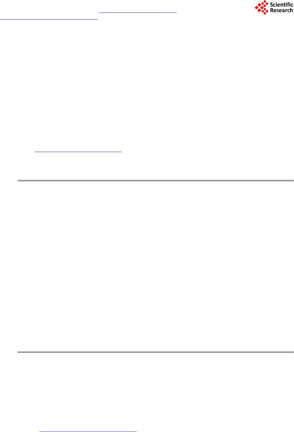
 Journal of Power and Energy Engineering, 2014, 2, 49-56 Published Online September 2014 in SciRes. http://www.scirp.org/journal/jpee http://dx.doi.org/10.4236/jpee.2014.29008 How to cite this paper: Chang, X.Y. and Nagano, H. (2014) Experimental Investigation on the Effection of Flow Regulator in a Multiple Evaporators/Condensers Loop Heat Pipe with Plastic Porous Structure. Journal of Power and Energy Engineering, 2, 49-56. http://dx.doi.org/10.4236/jpee.2014.29008 Experimental Investigation on the Effection of Flow Regulator in a Multiple Evaporators/Condensers Loop Heat Pipe with Plastic Porous Structure Xinyu Chang1, H. Nagano2 Department of Engineering, Nagoya University, Nagoya, Japan Email: chang@prop2.nuae.nagoya-u.ac.jp Received June 2014 Abstract Multiple loop heat pipes which have two evaporators and two condensers in one loop are a kind of active heat transfer device. Since they have two evaporators and two condensers, the operating mode also becomes multiple. This work discusses the cases that multiple loop heat pipes were operated with one condenser at high temperature and the other at low temperature. To avoid the high temperature returning liquid and keep the multiple loop heat pipes work properly, the flow regulator which was made of polyethylene was designed, fabricated and applied in this test. The effect of flow regulator was confirmed and an alyzed. In the test that large temperature difference existed between two sinks, it can be found according to the result that the flow regulator worked effectively and prevented the high temperature vapor to enter the inlet of common liquid line, which can keep the evaporators and returning liquid to operate at low temperature. With the in- crement of heat loads and the temperature difference between two sinks, the pressure difference between two condensers became larger and larger. When the pressure difference was larger than the flow regulator’s capillary force, the flow regulator could not work properly because the high temperature vapor began to flow through the flow regulator. According to the test data, the flow regulator can work properly within the sinks’ temperature 0˚C/60˚C and the two evaporators’ heat load 30/30 W. Keywords Flow Regulator, Loop Heat Pipe, Multiple Evaporators and Condensers, Two-Phase Heat Transfer 1. Introduction Loop heat pipes (LHPs) are two phase heat transfer devices which utilize the capillary force developed in the porous wick to circulate the working fluid. The heat can be transferred from heat source to radiator with the phase change occurred in working fluid [1]. The LHPs have been used in spacecraft and satellites to control 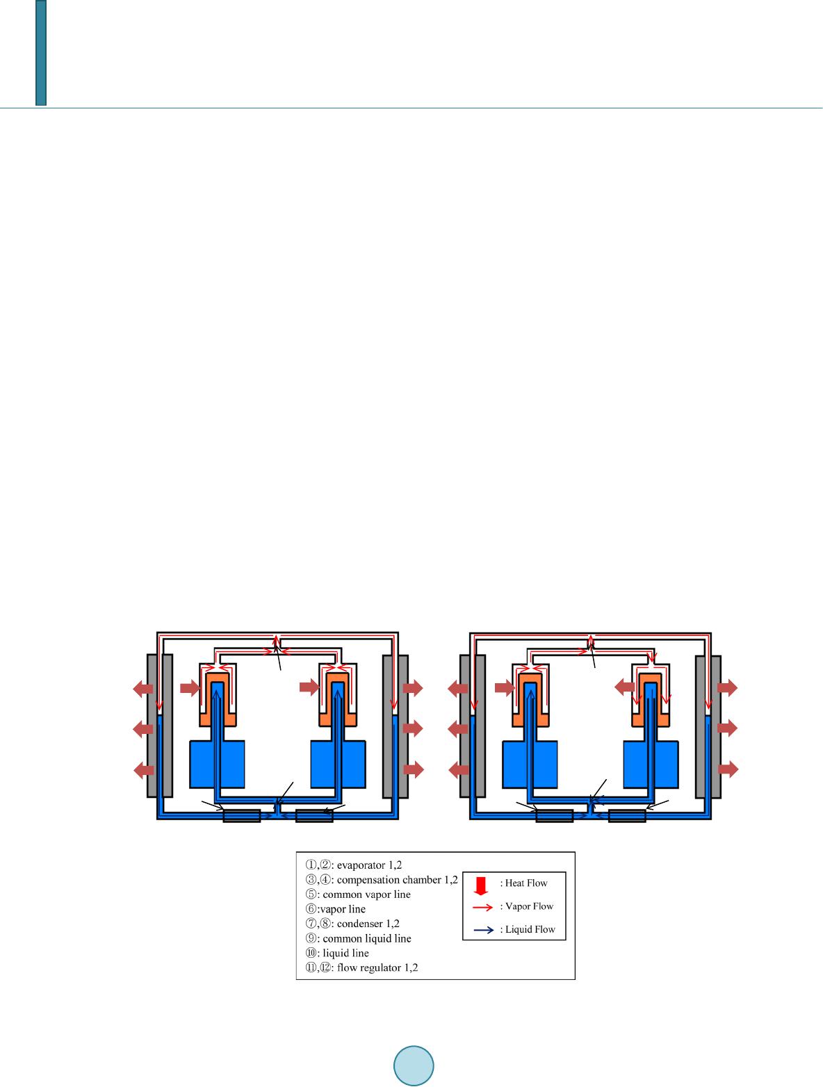 X. Y. Chang, H. Nagano temperature because the LHPs can transfer more heat than conventional heat pipes and be free from the electric- ity. To improve the efficiency of the LHP, multiple LHPs (MLHPs) which have two evaporators and two con- densers in one loop have been studied. The experiment to prove the operation of MLHPs was conducted in 1997 with the device that has two evaporators and one condenser [2]. The test which was conducted with the device that has two evaporators and two condensers was done in 2002 [3]. Calculating work was done in 2004 by Triem T. Hoang and Ku [4]. The flow regulator is a device taken advantage of capillary force to regulate the mass flow rate that flows along two condensers. Since the flow regulator can prevent the vapor with high temperature condensing at the inlet of the common liquid line and keep the whole loop to operate at low temperature, it becomes a necessary part of MLHPs. The flow regulator was utilized in the experiment of miniature MLHPs which was conducted in 2008 [5]. However, in that paper specific discussion on the effect of flow regulator was not conducted. Even though the MLHPs have been researched for almost 17 years, the experiment data and the investigation on flow regulator is insufficient. This work is conducted to figure out the property of flow regulator, which was designed, fabricated and applied in the experiment. The characteristic of flow regulator will be discussed by comparing the cases that were operated with flow regulator and without flow regulator. 2. Features and Principles of MLHPs Figure 1 shows the schematic and two working ways of MLHP. This MLHP is made of two evaporators (Evaps), two condensers (Conds), two vapor lines (VLs), two liquid lines (LLs), two compensation chambers (CCs), and two flow regulators (FRs). There is one porous wick in each Evap. In the case of Figure 1(a), heat loads are applied to both Evaps, which causes that the vapor generates in each Evap. and converges in the com- mon VL, after that the vapor separates and flows along each VL, then the vapor condenses into liquid in each Cond. The liquid converges in the common LL again and then separates in each LL which is connected with each CC. After the fluid reaches the CC, it will flow to the Evap to make up the volume that is evaporated in the Evap. The system is driven by the capillary force which develops in the porous wick in Eva p . If the total pres- sure drop of the loop is larger than the capillary force, the system will deprime since the vapor penetrates the Evap. In the case of Figure 1(b) heat load is only applied to one Evap. That will lead to the inverse flow in the Evap (a) Heat load to both evaporators (b) Heat load to one evaporator Figure 1. Schematic of a MLHP.  X. Y. Chang, H. Nagano which is not heated. So the vapor is condensed on the surface of wick before enters CC. In that case, the Evap unpowered will work as one Cond and acquire heat from the other powered one. The operating temperature of MLHP depends on the temperature of each CC. The higher CC’s temperature is the operating temperature of the loop. The feature and advantages of the MLHP is summarized as follows: 1) The MLHP can be used of cooling multiple heat source or a heat source with large thermal footprint be- cause that it has two Evaps. 2) For the reason that MLHP has two Conds, the heat dissipation can become more flexible. For example, if one condenser can not work because of high temperature. The other Conds can still work to dissipate heat ac- quired from the heat source. 3) Because of the heat exchange occurs between two Evaps. If one Evap is not applied with heat load, the working Evap can offer the heat to that un-working Evap, in which way to save the electricity which is used to keep warm. 3. The Design of Flow Regulator In the cases the temperature difference exists between two sinks. The vapor which flows along high temperature side may not be totally condensed, that leads to the high temperature of returning liquid and makes the loop op- erate at high temperature, in order to avoid that and raise the utilization of two sinks. The FR which can regulate the flow mass rate on each condenser side is applied to assure that more working fluid flows along the lower condenser temperature side. Figure 2 shows the schematic of the FR. In the Figure 2, the porous wick can prevent the vapor flowing through. For example, when the temperature of Cond 2 is high and the temperature of Cond 1 is low. Uncon- densed vapor from Cond 2 may exist and flow through the LL. When the vapor reaches the FR, it will be pre- vented by FR and other excess vapor flow will turn to flow through Cond 1, where it will be condensed to liquid and flow through the porous structure. In this way the mass flow rate can be controlled and the operating tem- perature descends. The pressure equation of FR is shown as follows: (1) In Equation (1), represents the capillary force of FR, the pressure loss through FR, the pressure loss from common VL to the LL confluence. According to Darcy’s law, the pressure drop through the wick can be calculated as (2) In Equation (2), represents pressure loss, the thickness of porous structure, the viscosity, the velocity of liquid which flows through the porous structure, the permeability of porous structure. The pressure loss through the FR which is applied in this experiment can be calculated as follows: 2 (() ) 2 l FR FR FR l wi mt Pd K µ ρπ − ∆= (3) In Equation (3), represents to the thickness of FR, the density of liquid, the diameter of FR, the mass flow rate. When is smaller than the pressure loss, the uncondensed vapor with high temperature will flow through FR and FR will not work properly. So the FR must be designed to satisfy Equation (1). According to the Figure 2. The schematic of flow regulator.  X. Y. Chang, H. Nagano mathematical model, the configuration of FR can be acquired. It is shown in Table 1. The pressure loss through FR is 1084 Pa when the temperature is 20˚C and the heat load is 20/20 W (working fluid: acetone). 4. Experiment System and Test Conditions Figure 3 illustrates the schematic of the MLHP which were designed and fabricated in this work. The tempera- ture measuring positions of MLHP were marked by black circles which shows the thermocouples numbers. In this experiment, 60 T-type thermocouples were used in order to measure each section of the MLHP. The Conds are enclosed in aluminum plates which are attached on copper plates. The copper plates’ temperature is con- trolled by chillers. Pure acetone (99.5%) is selected as a working fluid and the fluid inventory is determined as 60cc to make sure that the vapor exists in one CC in the case of low heat load and the liquid exists in one CC in the case of high heat load. In order to reduce the heat leak from Evap to CC and decrease the operating tem- perature, PTFE porous media is used as primary wicks which has less thermal conductivity than traditional metal wicks. In this test, the FR was set next the confluence of liquid line, which can be seen from Figure 3. Table 2 lists the configuration of MLHP and Table 3 lists the experimental conditions, two kinds of experi- ments were conducted to figure out the operating characteristics of the MLHP under different conditions. 1) Test with sink temperature changed under the constant heat load to investigate the operation with the large temperature difference between the sinks and confirm the behavior of the FR. 2) Test to confirm the behavior of the FR. This test was conducted in the conditions that sink 2 temperature was 0˚C/60˚C. Test (1) and Test (2) were conducted in the cases that the MLHP was operated with FR and without FR (w/o). 5. Experiment Data and Calculation Results 5.1. Test Result of Case1 In the experiment of case 1, the two heat loads were kept at 30/30 W, the temperature of sink1 was kept at 0˚C while the temperature of sink 2 rose 20˚C for every 50 minutes from 0˚C to 80˚C. The temperature profile oper- Table 1. Configurations of porous wick. Material Ultra High Molecular Weight polyethylene porous Diameter 10 mm Thickness 1 mm Pore radius 5 μm Table 2. The configurations of MLHP. L (mm) O.D. (mm) I.D. (mm) Evaporator 70 12 9.3 CC 45 36 34 Vapor line 770 3.18 1.75 Condenser 500 3.18 1.75 Liquid line 800 3.18 1.75 Primary wick 50 9.55 5 Table 3. Test conditions. case FR Heat load to Evap.1/Evap.2 (W) Sink temperature sink1/sink2 (˚C) 1-(a) with 30/30 0/0, 0/20, 0/40, 0/60, 0/80 1-(b) w/o 2-(a) with 0/0, 5/5, 10/10, 15/15, 20/20, 25/25, 30/30, 35/35, 40/40, 45/45, 50/50 0/60 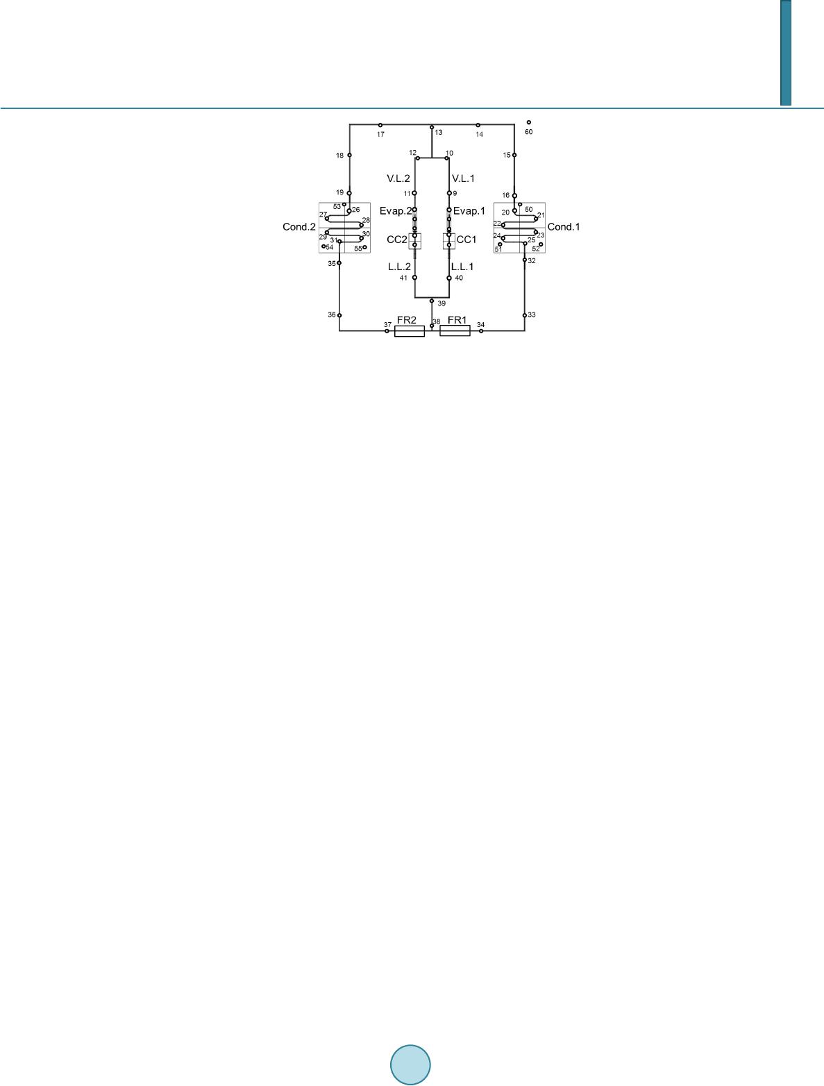 X. Y. Chang, H. Nagano Figure 3. Schematic of experiment system. ated without FR was shown in Figure 4 and the temperature profile operated with FR was shown in Figure 5. In the condition without FR, MLHP was operated with the stable temperature when the temperatures of sinks were 0˚C/0˚C and 0˚C/20˚C. When the temperature of sink2 reached 40˚C, the operating temperature began to rise, which made the loop system operate in higher temperature. That is because when temperature was 40˚C, the sink cannot condense all vapor. The uncondensed vapor flowed along the LL and finally met the subcooled liquid flowed from the other LL at the confluence of the LL, where condensation happened and large amount of heat emerged. That will make the returning liquid stay at high temperature and lead to the high operating tem- perature of the whole loop. To prevent that, the FR is required, which can make the fluid totally condensed when it reached the confluence of LL by changing the mass fluid rate of each condenser. In the condition with FR as shown in Figure 5, when sinks temperature rose to 0˚C/60˚C, the temperature of returning liquid began to rise and made the temperature of CC become higher, which indicates that on the tem- perature of 0˚C/60˚C, the uncondensed vapor began to penetrate the porous media located in FR. Even though the uncondensed vapor has penetrated the porous media, the MLHP can operate at lower tem- perature compared to the cases operated without FR because the mass flow rate on low temperature Cond side was much larger than the mass flow rate on high temperature Cond side. The temperature of each part of the MLHP in steady state are shown in Figure 6 with the conditions that heat loads were 30/30W and sinks temperature were 0˚C/0˚C, 0˚C/40˚C, 0˚C/80˚C. In the Figure 6, the left side were operated without FR while the right side were operated with FR. “Loop 1” means the loop which begins from Evap1, goes through Cond1 and ends at CC1. “Loop 2” means the counterpart of loop 1. In the case that the sinks temperatures were 0˚C/0˚C, all vapor was condensed in the condenser so no difference can be seen in both figures. In the case that the sinks temperature were 0/40˚C, the temperature of LL and Evap operated without FR are higher than the case with FR, from which that uncondensed vapor reached the confluence of LL can be in- ferred. In the case that the sinks temperature were 0˚C/80˚C, the temperature of Evap and LL operated without the FR became much higher while the temperature of Evap. and LL operated with the FR were stable, which in- dicates that the FR worked effectively. Table 4 shows the average temperature of evaporator and common liquid line, ΔT represents the temperature difference between the cases that were operated without FR and the cases that were operated with FR. According to the test data, the temperature of Evap and LL with the FR were 21˚C and 32˚C lower than the case without FR. 5.2. Test Result of Case 2 In the case 2, both Evaps were applied with the same heat load. One of the test data of the case 2 is shown in the Figure 7. In that case, two sinks were set at 0˚C/60˚C and the ambient temperature was 25˚C. In the test data, the heat load increased from 0 W to 45 W by 5 W for every step. In the Figure 7, the MLHP did not reach steady state until the heat loads rose to 15/15 W. After that the CC2’s temperature kept stable while the CC1’s temperature varied, which shows that the CC2 controlled MLHP’s temperature and CC1 was filled with liquid. The temperature of returning liquid is not same, that is because the vapor existed in the departure of liquid line. Since the CC1 was filled with liquid, more liquid flowed to the LL1, the remained fluid with the large percent of 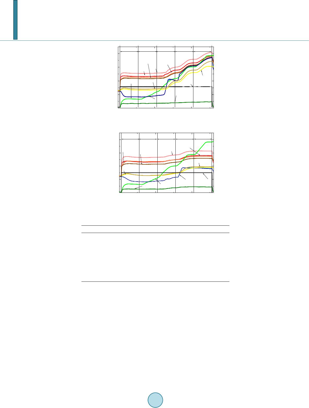 X. Y. Chang, H. Nagano Figure 4. Test data of case 3 (without FR). Figure 5. Test data of case 3 (without FR). Table 4. Temperature of Evap and common LL. Case Section w/o FR with FR ΔT 0˚C/0˚C Evap 48 49 −1 Common LL 13 14 −1 0˚C/40˚C Evap 65 58 7 Common LL 56 41 15 0˚C/80˚C Evap 80 59 21 Common LL 72 40 32 vapor flowed to CC2 and kept the LL2 in high temperature. In the Figure 7, the temperature of LL2 is the same with the temperature of VL from 20/20 W to 30/30 W, which indicated that the vapor existed in LL2, too. There is temperature overshoot on LL1, that is because the reverse flow happened when heat load changed. Also the temperature of LL1 became closer to LL2 with the increment of heat loads. The max heat loads in this case were 35/35 W. In the Figure 8, the operating temperature decreased first and then increased, which was one effect of FR. When the heat load was small, the porous media located in FR worked and stopped the uncondensed vapor. As the result, more and more liquid flowed to the side whose sink temperature was low. That reduced the tem- perature of returning liquid and made the operating temperature low. However, when the heat load rose to the value that high temperature vapor began to penetrate the FR, more heat from high sink temperature side leaked to the returning liquid. With the increment of heat load, more and more uncondensed vapor penetrated the FR, which made the temperature of returning liquid high and led to the temperature increasing of CC. The max heat load of this case was higher than the case that operated without FR. In this case, the operating temperature rose at the heat load of 30/30 W, which indicated that at that time the high temperature vapor penetrated the FR. In the Figure 8, when the heat loads were fixed to 30/30 W, the operating temperature rose at the temperature of 0100 200 0 20 40 60 80 Evap.1(1-4) Time (minute) Temperature (℃), Heat load(W) Evap.2(5-8) V.L.2(9-10) V.L.1(11-12) Cond.2(20-25) Cond.1(26-31) L.L.2(40) L.L.1(41) C.C.1(42-45) Heat load C.C.2(46-49) 0/0 0/20 0/400/60 0/80 0100 200 0 20 40 60 80 Time (minute) Temperature (℃), Heat load (W) Evap.1(1-4) Evap.2(5-8) V.L.2(9-10) V.L.1(11-12) Cond2.(20-25) Cond1.(26-31) L.L.2(41) L.L.1(40) C.C.1(42-45) C.C.2(46-49) Heat load 0/00/20 0/400/800/60 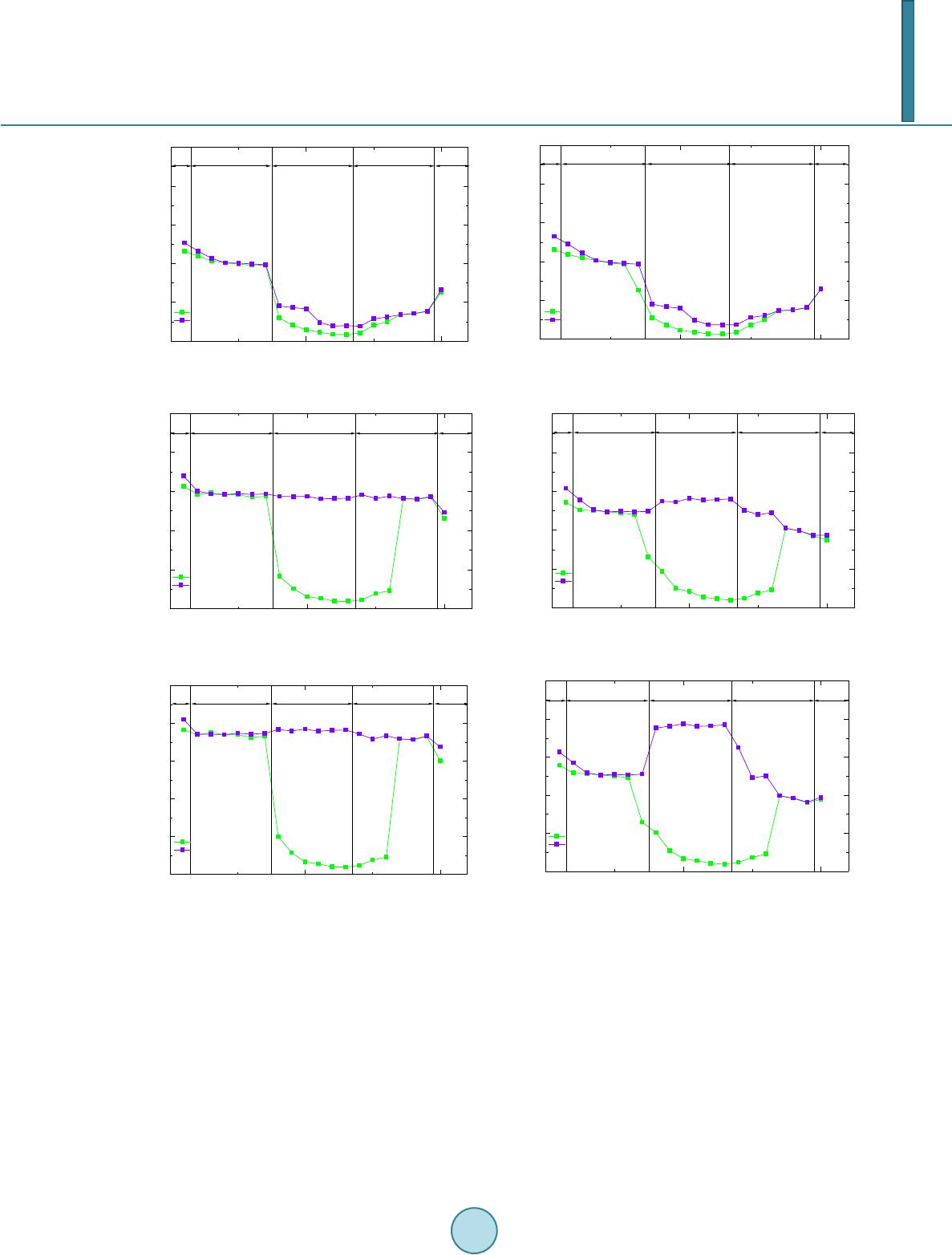 X. Y. Chang, H. Nagano (a-1) sink 0˚C/0˚C without FR (b-1) sink 0˚C/0˚C with FR (a-2) sink 0˚C/40˚C without FR (b-2) sink 0˚C/40˚C with FR (a-3) sink 0˚C/80˚C without FR (b-3) sink 0˚C/80˚C with FR Figure 6. The temperature of all parts of MLHP in steady state. sinks 0˚C/60˚C, which indicated that at that time the uncondensed vapor reached the confluence of LL. So the experiment data in the case 2 is in accordance with case 1, which shows that the FR can work properly if the heat load is smaller than 30/30 W and the sink temperature is lower than 0˚C/60˚C. 6. Conclusion The FR was designed and produced in this work. Several experiments were conducted to figure out the effect of FR. In the case that the MLHP was operated with different sink temperature and stable heat loads. The case that MLHP was operated with FR makes MLHP operate at lower temperature. In the case that the temperature of two sinks were 0˚C/80˚C, the temperature of evaporator and the confluence of LL were reduced because of the FR’s 010 20 0 20 40 60 80 100 Thermocouples Position Temperature (℃) Evap. V.L. Cond. L.L. C.C. experiment data (loop 1) experiment data (loop 2) 010 20 0 20 40 60 80 100 Thermocoupous Position Temperature (℃) experiment data(loop 1) experiment data(loop 2) Evap. V.L. Cond. L.L. C.C. 010 20 0 20 40 60 80 100 Temperature (℃) Thermocouples Position Evap. V.L. L.L. Cond. C.C. experiment data(loop 1) experiment data(loop 2) 010 20 0 20 40 60 80 100 Temperature (℃) Thermocouples Position experiment data (loop 1) experiment data (loop 2) Evap. V.L. Cond. L.L. C.C. 010 20 0 20 40 60 80 100 Thermocouples Position Temperature (℃) Evap. V.L. Cond. L.L. C.C. experiment data (loop 1) experiment data (loop 2) 010 20 0 20 40 60 80 100 Thermocouples Position Temperature (℃) Evap. V.L. Cond.L.L. C.C. experiment data (loop 1) experiment data (loop 2) 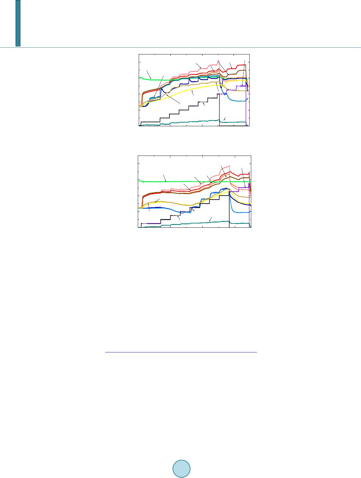 X. Y. Chang, H. Nagano Figure 7. Test data of case 4 (without FR). Figure 8. Test data of case 4 (with FR). effect. In the case that the temperature of two sinks (with large temperature difference) was stable, the MLHP operated with FR can transport more heat. References [1] Ku, J. (1999) Operating Characteristics of Loop Heat Pipes. 29th International Conference on Environmental System, Denver, 12-15 July 1999, No. 1999-01-2007. [2] Bienert Wol f, W.B., Nikitkin, M.N., Maydanik, Y.F., Fershtat er, Y., Vershinin, S. and Gottschlich, J.M. (1997) The Proof-of-Feasibility of Multiple Evaporator Loop Heat Pipes. Sixth European Symposium on Space Environmental Control Systems, Noordwijk, 20-22 May 1997, 393-400. [3] Delil, A.A.M., May da nik , Y.F., Chernyshova, M.A. and Pastukhov, V.G. (2003) Development and Test Results of a Multi-Evaporator-Condenser Loop Heat Pipe. AIP Conference Proceedings, 654. [4] Hoang, T.T. and Ku, J.T. (2004) Mathematical Modeling of Loop Heat Pipes With Multiple Capillary Pumps and Mul- tiple Condensers. http://ntrs.nasa.gov/archive/nasa/casi.ntrs.nasa.gov/20040171388.pdf [5] Ku, J.T., Ottenstein, L. and Douglas, D. (2008) Multi-Evaporator Miniature Loop Heat Pipe for Small Spacecraft Thermal Control. 49th AIAA/ASME/ASCE/AHS/ASC Structures, Structural Dynamics, and Materials Conference, 7-10 April 2008. 0100 200 300 0 20 40 60 80 Time (minute) Temperature (℃), Heat load (W) Evap.1(1-4) Evap.2(5-8) Heat load1 Heat load2 V.L.1(11-12) V.L.2(9-10) Cond.2(20-25) Cond.1(26-31) L.L.1(41) L.L.2(40) C.C.1(42-45) C.C.2(46-49) 0100200 300 0 20 40 60 80 Time (minute) Temperature (℃) Power (W) Heat load1 V.L.1(11-12) V.L.2(9-10) Evap.1(1-4) Evap.2(5-8) Cond.2(20-25) Cond.1(26-31) C.C.2(46-49) C.C.1(42-45) L.L.1(41) L.L.2(40) Heat load2
|