 Journal of Computer and Communications, 2014, 2, 68-74 Published Online September 2014 in SciRes. http://www.scirp.org/journal/jcc http://dx.doi.org/10.4236/jcc.2014.211009 How to cite this paper: Zeng, J., Chen, H.B. and Yin, Y. (2014) A Humanoid Robot Gait Planning and Its Stability Validation. Journal of Computer and Communications, 2, 68-74. http://dx.doi.org/10.4236/jcc.2014.211009 A Humanoid Robot Gait Planning and Its Stability Validation Jian Zeng, Haibo Chen, Yan Yin Department of Modern Mechanics, University of Science and Technology of China, Hefei, China Email: eyuren@mail.ustc.edu.cn, hbchen@ustc.edu.cn, yinyan@mail.ustc.edu.cn Received August 2014 Abstract Gait planning based on linear inverted pendulum (LIPM) on structured road surface can be quick- ly generated because of the simple model and definite physical meaning. However, over-simpl ifi- catio n of the model and discontents of zero velocity and acceleration boundary conditions when robot starts and stops walking lead to obvious difference between the model and the real robot. In this paper, p a ram ete rize d gait is planned and trajectories’ smoothness of each joint angle and centroid are ensured using the 3-D LIPM theory. Static walking method is used to satisfy zero ve- locity and acceleration boundary conditions. Besides, a multi-link model is built to validate the stability. Simulation experiments show that: despi te of some deviation from the theoretical solu- tion, the actual zero-moment point (ZMP) is still within the support polygon, and the robot walks steadily. In c onse quence , the rationality and validity of model simplification of LIPM is demon- strated. Keywords Humanoid Robot, Gait Planning, 3-D LIPM, Stability Validation, Multi-Link Model 1. Introduction Reasonable walking pattern planning is the foundation to achieve stable bipedal walking due to the complexity of a humanoid robot mec ha nism. So far the mainstre am gait planning methods are based on the simplified phys- ical model [1], the bionics [2], the energy optimal method [3], the intelligence technology [4] et al. T he fi rst method has a simple model and definite physical meaning, but the robustness, Anti-jamming ability and adapta- bility to the practical walking e nviro nment are poor due to the oversimplification from the real model. The da- tabase does not have the feature for sharing due to the difference between the robot and the human for the second method. The gait planning method based on energy optimization can not be used to real-time application for its complex ity in modeling and optimization procedure. The intelligent algorithm was proposed in recent years and there are a series of problems remained to be solved, including the algorithm’ s effectiveness, real-time performance, convergence et al. [5]. This paper is confined to the robot walking on flat ground, which is simple but the robot might lose its stability if an unsuitable walking pattern and gait parameters are selected. The 3-D LIPM is used for gait planning, thus leading to simple formula, definite physical meaning and outstanding adap- tability to structured roads. 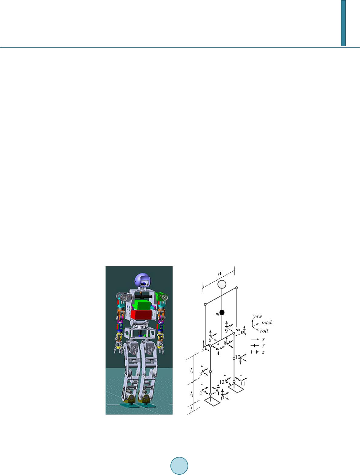 J. Zeng et al. The ultimate aim of gait planning is to realize a stable walking, so walking stability needed to be checked to con fi rm the feasibility and effectiveness of the gait planning. The model of 3-D LIPM has deviatio ns with real robot on its assumption that the mass of the robot is condensed to one point and the mass of lower limbs is neg- lected [6], which will usually lend to instability. So in this paper, walking stability based on the ZMP stability criterion is calculated by using a multi-link model which is closer to the real robot by considering the lower limbs’ mass. Meanwhile the virtual prototype is built for simulation. Through these two treatments, the rational- ity and validity of the simplifi ca tion of the 3-D LIPM is verified. 2. Humanoid Robot Kinematics Modeling The robot can be simplified into a multi-link model of 12 degrees of freedom assuming that the upper body keeps upright and relative rest when it walks. The local coordinate system at each joint is set up as Figure 1 by D-H rule [7]. The 0 coordination is the world coordinate system (WCS) fixed on the ground. 1 - 12 coordina- tions are the local coordinations. Aft er calculating the homogeneous transformation matrixes between the local coordinations, and knowing the angles at each joint, the WCS coordinates of any point in the local coordinate system can be calculated based on the chain rule of homogeneous transformation, thus providing the WCS coor- dinates and orientations of each link for stability validation. 3. Humanoid Robot Gait Planning Each joint angle trajectory can be calculated by inverse kinematics once the trajectories of the center of mass (CM) and the swing legs are planned, thus the corresponding gaits are generated. The trajectories of swing legs are fitted by polynomial interpolation through the parameters as step length, step cycle, zero speed and zero ac- celeration at the time swing leg leaving and landing ground. Here we focus on the design of trajectory for CM. 3.1. Trajectory of CM Figure 2 shows the 3-D LIPM which is proposed for trajectory planning of CM under the assumption that the mass of lower limbs is neglected, the mass of the upper body is condensed to one point and its vertical height remains constant. (a) (b) Figure 1. Virtual prototype and multi-link model: (a) Virtual prototype model; (b) Multi-link model. 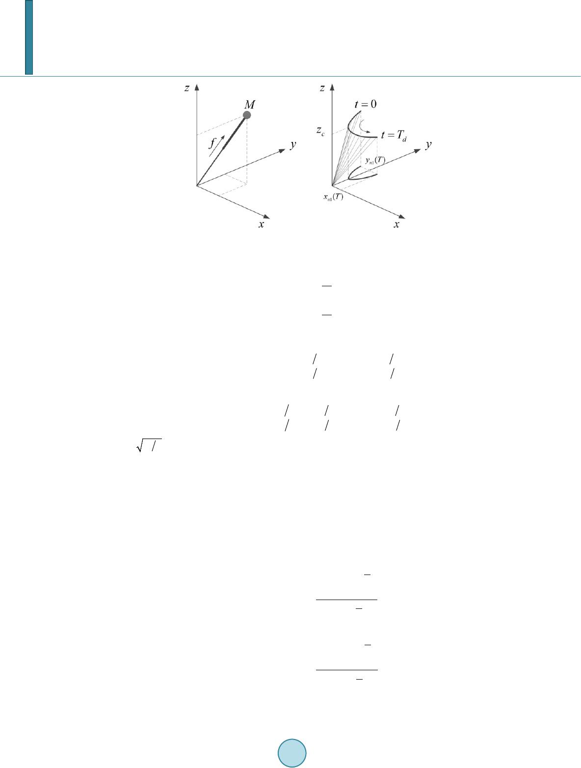 J. Zeng et al. Figure 2. 3-D LIPM model and its trajectory. In this case, the motion differential equations of 3-D LIPM are given by: (1) The solutions are: ( )() ( ) ( ) ( ) ( )() ( ) ( ) ( ) cosh 0 cosh0 sinh sin00h cc c ccc x txtTTxt y T ttTTyytT= = + + (2) And the first d e rivative s versus time are: ( )() ( ) ( ) ( ) ( )() ( ) ( ) ( ) sinh cos 0sinh0 cosh 0 h0 cc c cc c xt xTtTxtT tyyy TtTtT = + = + (3) where, . 3.1.1. Middle Gait For single leg support phase: assuming the time section is , the CM trajectory component for vector and vector are and , respectively. Because of symmetry and periodicity conditions, it is re- quired that: ( )( )()( ) ()( )()( ) 1 1 11 11 1 1 0, 00, 0 n nn nn n n n xTxxT x TTy yyy = = =− = − (4) Substituting Equation (4) into Equation (3), one gets ( ) ( ) ( ) ( ) 1 1 1 1 0 1 1 0 1 0 1 0 c c c c T T n T T nT T c n nT T c xe x Te ye y Te + = − − = + (5)  J. Zeng et al. When the initial CM positions and are given, the trajectory of CM can be calculated by substituting Equation (5) into Equation (2). For double leg support phase, in order to keep the velocity and acceleration of CM cont inuous in the period that the robot walks from one final LIPM moment to the next initial LIPM moment, a double leg support phase needs to be considered. The sketch of axis is shown in Figure 3. Assuming the time section is , the and vector trajectories of CM and can be calculated by piecewise polynomial interpolation. 3.1.2. Start Gait and Final Gait The start gait and final gait in single leg support phase correspond to the period of and , re- spectively. The CM trajectories of this phase can be calculated in the same way by considering the symmetry and periodicity conditions. The robot keeps static before starting to walk. To satisfy the conti n uous requirements of velocity and accele- ration of CM, the swing legs need to retreat to get an accelerating process for CM until the velocities and acce- lerations are equal to the initial start time of LIPM, assuming the section time is . Similarly, after the final gait, the swing legs need to take a distance forward from support leg, and the CM moves from the final state of LIPM to static in the double leg support phase. The trajectories of above static walking phases are fitted by po- lynomial interpolation. 3.2. Joint Angle Trajectory It is supposed that , , , , , , . The trajectories of lower limb joint angles including the phase , start gait by left leg, three cycles of middle gait, and the final gait are calculated by inverse kinematics as Figure 4 (take the right leg for example). 4. Stability Validat ion 4.1. Theoretical Calculation A multi-link model, shown in Figure 1(b), is used for theoretical calculation. It is assumed that inertial tensor of each link around its CM is neglected, the equations of ZMP are as follows: () () { } ( ) 1 1 N i iiizi i xN ii i mzgxzpx p mz g = = + −− = + ∑ ∑ (6) () () { } ( ) 1 1 N i iiizi i yN ii i mzgyzp y p mz g = = + −− = + ∑ ∑ (7) Figure 3. A Complete gait period on x axis.  J. Zeng et al. Figure 4. Joint angle trajectories of right leg. The WCS trajectories of CM of each link are calculated by substituting each joint angle from the gait plan- ning into multi-link kinematics model, where the victory and acceleration are calculated by the difference me- thod. Substituting all these above into Equatio ns (6) and (7), the solutions of ZMP trajectories are shown in Figure 5. It is indicated by comparing Figure 5(a) and F igur e 5( b) that walking stability improves obviously in the static walking phase on the start and stop moment and double leg support phase when two gait switch- ing gets smooth and conforms to the actual rule. Fig ure 5(b) shows that the actual ZMP trajectory has deviation from the theoretical value. However, after the two treatments are introduced in, the actual ZMP is within the support polygon which means the deviation is very small, especially in single leg support phase, the stability margin is enough for steadily walking. By the way, the CM trajectories in double leg support phase need to continuously optimized. Thus it is t heoretically proved that the differences do exist between the 3 -D LIPM and the actual robot, but the simplification is reasonable and effective.  J. Zeng et al. 4.2. Virtual Prototype Simulation Solidworks is used to build the virtual prototype of a humanoid robot, ADAMS is used to simulate the robot’s walking, the simulation diagram of one of the cycle gait is shown in Fig ure 6. With the simulation result, it is concluded that the robot can walk steadily according to the planned gait. The rationality and effectiveness of 3-D LIPM is further confirmed by simulation. 5. Conclusions LIPM is a common model for humanoid robot gait planning, but the model is over-simplified, ignoring the mass of lower limbs, the moment of inertia et al., which lead to obvious deviation from the real robot. Based on LIPM gait planning, a multi-link model is used to calculate the ZMP for stability validatio n. At the same time, a virtual (a) (b) Figure 5. Trajectory of ZMP: (a) Trajectory of ZMP without static walking phase and double leg support phase; (b) Trajec- tory of ZMP with static walking phase and double leg support phase. Figure 6. Virtual prototype simulation result.  J. Zeng et al. prototype is built for simulation. By gait planning and stability validation above, conclusions are drawn as fol- lows: 1) 3-D LIPM is effective for structured pavement gait planning, the additional improvement of boundary con- ditions on the start and stop moment is effective and conforms to the actual rul e . 2) The trajectories of joint angles are designed more smoothly after considering the speed and acceleration discontinuity problems when two gait cycle switching, which increases the walking stability of the robot. 3) The effect on ZMP by LIPM simplification is shown and the rationality of si mpli fic ation is ver ified by theoretical calculation and simulation. Thus, the simplification can be used for real robot walking planning. 4) The stability can be validated by the relations hip bet ween ZMP trajectory and support polygon when robot walks, which is applicable to most structured road conditions. References [1] Fu, C.L. and Chen, K. (2008 ) Gait Synthesis and Sensory Control of Stair Climbing for a Humanoid Robot. IEEE Transactions on Industrial Electronics, 55, 2111-21 20 . htt p:// dx.d oi. or g/10 .11 09 /TIE .20 08. 9212 05 [2] Hirai, K., Hiro se, M., Haikawa, Y. and Takena ka, T. (1998) The Development of Honda Humanoid Robot. Proceed- ings of the 1998 IEEE International Conference on Robotics and Automation, Leuven, 16-20 May 1998, 1321-1326 . [3] Nguyen, T.P., Kim, D.W. , Kim, H.K. and K im, S.B. (2008) An Optimal Control Method for Biped Robot with Stable Walking Gait. Proceedings of the 2008 IEEE-RAS International Conference on Humanoid Robots, Korea, 1-3 Decem- ber 2008, 211-218. [4] Katic, D. and Vukobratovic, M. (2003) Survey of Intelligence Control Techniques for Humanoid Robots. Journal of Intelligence and Robotic Systems, 37, 11 7-141 . http://dx.doi.org/10.1023/A:1024172417914 [5] Fu, G.P. and Yang, Y.M. (20 11 ) Survey and Prospect on Walking Control Strategies for Humanoid Robot. Machine Tool & Hydraulics, 39, 154-15 8. (in C hin ese) [6] Shuuji, K., Hirohisa, H., Kazuhito, Y. and Kensuke, H. (2005) Humanoid Robots. Ohm-sha Ltd, Tokyo. [7] Ch en, K. and Fu, C.L. (2010) Humanoid Robot Theory and Technology. Tsinghua University Ltd., Beijing. (in Chi- nese)
|