Energy and Power En gi neering, 2011, 3, 120-134
doi:10.4236/epe.2011.32016 Published Online May 2011 (http://www.SciRP.org/journal/epe)
Copyright © 2011 SciRes. EPE
Comparative Simulation Study between Gate Firing Units
for HVDC Rectifier Based on CIGRE Benchmark Model
Bhaba Priyo Das, Neville Watson, Yonghe Liu
Department of Electrical and Computer Engineering, University of Canterbury, Christchurch, New Zealand
E-mail: bhaba.das@pg.canterbury.ac.nz
Received February 28, 2011; revised March 22, 2011; accepted April 2, 2011
Abstract
A simulation study between the DQO gate firing unit (GFU) and a proposed GFU for high voltage direct
current (HVDC) rectifier based on the CIGRE benchmark model in Matlab/Simulink is carried out. The
proposed GFU does not use traditional phase lock loop (PLL) and offers structural simplicity, fast response
and immunity to ac system voltage unbalance, harmonics, voltage sag, frequency jump and phase jump etc.
Since there is no loop filter, no tuning issues are involved. Advantages of the proposed GFU are confirmed
by extensive simulation results.
Keywords: CIGRE HVDC, Phase Lock Loop, Rotating reference Frame, Simulation
1. Introduction
High voltage direct current (HVDC) transmission sys-
tems are being increasingly used nowadays. A total of
47.6 GW of long-distance HVDC has been installed
worldwide from 1962 to 2009 with 50% of this capacity
constructed after the year 2000 and additional 26.5 GW
of new long-distance HVDC are under construction [1].
HVDC systems are usually simulated using PSCAD/
EMTDC or EMTP. This paper simulates the HVDC rec-
tifier based on the CIGRE benchmark model using Mat-
lab/Simulink. References [2-4] describe simulation stud-
ies of different gate firing units (GFU) used in HVDC
using EMTP.
The first use of phase lock loops (PLL) for synchroni-
zation using a voltage controlled oscillator (VCO) was
proposed in [5]. This is referred as the Conventional
GFU, based on a VCO and a PLL. The ac system voltage
is called as commutating voltage (Vcom). The main objec-
tive of this GFU is to generate a voltage signal Vsync,
synchronised with Vcom. In the conventional GFU, the
error between these two signals is fed to a VCO to
change the frequency and phase of Vsync so that error is
minimized. Vsync is then used to derive equidistant firing
pulses for the thyristors of the HVDC rectifier. Since,
this GFU has low pass filter (LPF) in the loop to filter
out the internally generated 2nd harmonic term; it intro-
duces a compromise between transient response and dis-
turbance rejection. The analysis of this GFU is reported
in [2].
Another GFU, trans-vector PLL [3], is widely used
now-a-days. The main idea here, is to calculate the dif-
ference between the phase angle of Vcom and Vsync and
maintain this value to zero by means of a propor-
tional-integral (PI) controller (Figure 1). This trans-
vector PLL has several deficiencies [6] which are revised
in section II.
All PLLs have stability issues because these are closed
loop systems. Tuning the PI controller parameter, as in
case of conventional PLL with LPF, with a high band-
width results in a quicker response for transients like
phase jumps, voltage sags and swells, etc. However, a
high bandwidth is results in poor filtering of noise and
harmonics and also, can produce instability. Low band-
width PI controller is better for noise, harmonics and
stability but they have a poor speed of response for tran-
sients. Additionally, there is a trade-off in selecting PI
controller gains for phase and frequency jumps. Tran-
sient response to phase step is better for over-damped
system. Transient response can be improved if band-
width is increased. This leads to filtering problems.
Transient response to frequency step is better for un-
der-damped system. For under-damped system the set-
tling time is faster as compared to the over-damped sys-
tem but with higher over-shoot.
This paper presents a new open loop structure as an
alternative to PLLs for synchronization and firing pulse
ge eration. This alternative synchronization and firing n
B. P. DAS ET AL.
121
Figure 1. Block diagram of trans-vecto r PLL GFU.
pulse generation scheme is based on transforming the ac
system voltage into rotating reference (dq-reference)
frame and generate the fundamental positive and nega-
tive sequence component. This scheme can operate under
unbalanced, distorted and variable-frequency conditions
of the mains voltage. The success of this scheme depends
on real time frequency detection algorithm used to track
the frequency of the ac system voltage.
The main features of the proposed GFU can be sum-
marized as:
1) It is immune to mains voltage unbalance, harmonics,
voltage sag, phase jump, frequency variation etc.
2) There is no stability or tuning issue involved as it is
an open loop structure without any filter in the loop.
3) The transient response does not depend on the am-
plitude of ac system voltage.
4) The time of transient response is always fixed for
fixed frequency applications. For variable frequency ap-
plications, this depends on the frequency detection algo-
rithm, to track frequency during the transient. The faster
the frequency lock, faster is the response.
5) This method offers structural simplicity which can
be easily implemented both in hardware and software
environments.
The model used here is a 6-pulse HVDC rectifier sys-
tem similar to the one considered in [3].
2. Trans-Vector PLL
The ac system voltages Va, Vb and Vc are first trans-
formed to the stationary reference frame using (1):
11
1
222
=333
222
a
b
c
V
VV
VV




 
 

 



(1)
The error signal, e, is given as:
cos sineV V

 (2)
The error signal is fed through a PI controller to gen-
erate a reference frequency for the VCO. The center fre-
quency of the VCO is set at 50 Hz. The output of the PI
controller can change the frequency output of the VCO
accordingly. The output of the VCO is a signal propor-
tional to phase angle. This signal is used to generate the
Sine-Cosine waveforms which are fed back to the multi-
pliers to generate the error signal. Under steady state, this
error is reduced to zero and output Vsync will be in syn-
chronism with Vcom.
The closed loop transfer function from Figure 2 is:

11
1
1
mp
mp
s
VK
1
s
s
Hs s
VK
s
s
(3)
H(s) can be rewritten the form:

2
2
2
2
nn
nn
s
Hs ss
 
2


(4)
where
P
m
n
V
and 22
nP
n
m
K
V


A well designed PLL for power system applications
should meet the following criteria:
1) Damping factor, ξ = 1 for optimum phase and fre-
quency jump transient response.
2) Narrow bandwidth (low ωn) for immunity against
unbalance, harmonics and noise.
Phase margin (Pm) is a very useful parameter used to
specify the control system performance of the PLL be-
cause it is related with ξ [7]:
Figure 2. Closed loop transfer function of trans-vector PLL
GFU.
Copyright © 2011 SciRes. EPE
122 B. P. DAS ET AL.
124
tan 2241Pm
 
 (5)
A PLL is stable if its Pm is positive and unstable if its
Pm is negative. Pm also gives a qualitative indication of
the loop damping. Since smaller damping is rarely
wanted, Pm below 50˚ is usually not recommended i.e. ξ
less than 0.5 is avoided. In [3] the recommended value of
Pm is given as: 60˚ and ωn40 Hz. These two selections
give a good compromise between a fast response and a
small synchronising error. Simulation results for
trans-vector PLL under different conditions is presented
next for Vm = 230Vrms, ξ = 0.6 and ωn = 2π (40) rad/s. KP =
1.31 and τ = 4.77 ms are calculated from (4).
The simulation results show: Line voltages Va, Vb, Vc
(in Volts), Phase angle, θsync (in Radians), Vsync (pu) and
error signal, e (in Volts). The x-axis represents time (in
seconds).
2.1. Under Ideal Vcom
As seen from Figure 3, the trans-vector PLL has a good
performance with ξ = 0.6 and ωn = 2π (40) rad/s when
Vcom is balanced and without any harmonics.
2.2. Under Presence of Harmonics in Vcom
Figure 4 shows that when Vcom gets corrupted with har-
monics, PLL fails to obtain the correct angular position
2.3. Under Presence of Voltage Unbalance Vcom
Similarly, when Vcom has unbalance, PLL again fails to
obtain the correct angular position (Figure 5).
2.4. Under Loss of Vcom for Few Cycles
Two different cases are simulated for loss of Vcom.
2.4.1. Ideal Vcom
If there is a loss of Vcom, the response of PLL depends on
the harmonics present in Vcom. Figure 6 shows that PLL
falls to its “free running” mode if Vcom is ideal.
2.4.2. Dist orted Vcom
Figure 7 shows that if there is a loss of Vcom when Vcom is
corrupted due to harmonics, PLL fails to obtain correct
angular position.
2.5. Under Phase Jump of 20˚ in Vcom at 0.1 s
As shown in Figure 8, under 20˚ phase jump and har-
monics in Vcom, it has a fairly good transient response
(around 10 ms).
Figure 3. Results of trans-vector PLL GFU under ideal Vcom.
Copyright © 2011 SciRes. EPE
B. P. DAS ET AL.
123
Figure 4. Results of trans-vector PLL GFU for 5th and 7th harmonics in Vcom.
Figure 5. Results of trans-vect or P LL GFU for unbalance in Vcom.
Copyright © 2011 SciRes. EPE
124 B. P. DAS ET AL.
Figure 6. Results of trans-vector PLL GFU for loss of Vcom from 0.1 s to 0.2 s.
Figure 7. Results of trans-vector PLL GFU loss of Vcom from 0.1 s to 0.2 s and5th and 7th harmonics in Vcom.
Copyright © 2011 SciRes. EPE
B. P. DAS ET AL.
Copyright © 2011 SciRes. EPE
125
Figure 8. Results of trans-vector PLL GFU for 20° phase jump in Vcom.
2.6. Under Frequency Jump of 1 Hz at 0.1 s
For frequency jump of 1Hz, transient response is less
than 20 ms (Figure 9).
The trans-vector PLL does not have the problem of
internal second harmonic generation and has fairly good
transient responses but, as revised in this section, it is
sensitive to disturbances. Phase and frequency jumps
also affect the error signal in such a way that it intro-
duces trade-offs. While there have been attempts to solve
most of these problems in [8-15], structural and compu-
tational complexity has increased with each attempt.
Usually, HVDC transmission systems use PI controllers
with fixed PI gains. Such controllers work well for a
small range of disturbances. However, when the ac sys-
tem voltage has disturbances greater than this range, the
PI controllers may not be able to provide desired re-
sponse. In that case, tunable PI controllers are required.
3. Proposed GFU
Since higher order harmonics like 21st, 23rd etc. are in-
significant for industrial power systems, this method is
considered here only up-to the 19th harmonic. This can
be extended to higher harmonics also, if needed. In [16],
Yao proposed the concept of extracting the fundamental
component with a short delay in rotating reference frame.
The block diagram is shown in Figure 10. Let, Vdq(t)
represent the voltages in dq-reference frame. Delaying
Vdq(t) by τ (¼ of the fundamental cycle), Vdq(t – τ) is ob-
tained which is same in amplitude but exactly 180° out of
phase. Thus, by adding the delayed signal to the original
signal cancellation of negative sequence, 5th harmonic,
7th harmonic etc is obtained. The amplitude is doubled
which can be divided by 2 to get the original amplitude.
This is a very simple and fast method by which DC
components in dq-reference frame is obtained. Higher
order harmonics like 11th, 13th etc can also be cancelled
by introducing appropriate delays.
The block diagram of the proposed GFU is shown in
Figure 11. After cancelling out various distortions, the
fundamental positive sequence component (Vp) and
phase angle (αp) is obtained.
Once the magnitude of Vp and αp is obtained, a set of
balanced three phase voltages, Vsync which are in phase
with the positive sequence of the Vcom, are calculated by
adding or subtracting 2π/3 radians. Once the three set of
voltages are obtained, the first firing pulse (S1) is ob-
tained at the zero crossing of phase to phase Vsync. The
remaining firing pulses are obtained after delaying S1 by
60˚ [17]. The delay of 60˚ is maintained by calculating
the time period from the frequency of Vcom.
B. P. DAS ET AL.
Copyright © 2011 SciRes. EPE
126
Figure 9. Results of trans-vector PLL GFU for 20˚ phase jump in Vcom.
Figure 10. Process of extracting fundamental component
using Yao’s method.
1
tan q
d
V
V
22
p
dq
VVV

q
V
d
V
Figure 11. Block diagram of proposed GFU.
This section shows the generation Vsync from Vcom un-
der various corrupting sources such as voltage harmonics,
unbalance, sags, phase outage, frequency jump and phase
jump. The simulation results show: Vcom, Vsync (phase to
ground), Vsync (phase to phase) (in Volts), Phase angle,
θsync (in Radians) and firing pulse (S1) to first thyristor.
The x-axis represents time (in seconds).
3.1. Under Ideal Vcom
As seen from Figure 12, the proposed GFU has a good
performance when Vcom is ideal. Vsync is precisely gener-
B. P. DAS ET AL.
127
ated using from Vcom.
3.2. Under Presence of Harmonics in Vcom
In this case, 5th and 7th harmonic components are added
to Vcom. From Figure 13, it is seen that correct phase
angle is obtained for this case also. A firing pulse syn-
chronised at the zero crossing of Vsync (phase to phase)
and delayed by appropriate firing angle (α) is obtained.
3.3. Under Presence of Voltage Unbalance Vcom
In Figure 14, Vcom is unbalanced. It is seen that even
under unbalance correct phase angle is obtained.
3.4. Under Loss of One Phase of Vcom for Few
Cycles
Loss of phase A is simulated in Figure 15 from 0.1 s to
0.16 s. Clean Vsync is obtained in this situation too. Cor-
rect firing pulse can be maintained despite loosing one of
the phases of Vcom.
3.5. Under Phase Jump of 45˚ in Vcom at 0.1 s
A phase jump of 45˚ at 0.1 s under presence of harmon-
ics in Vcom is simulated in Figure 16. A clean Vsync is
obtained from the calculated fundamental positive se-
quence magnitude and phase angle.
3.6. Under Frequency Jump of 1 Hz at 0.1 s
A frequency step of 1Hz at 0.1s is simulated for this case.
Figure 17 shows that after 1 cycle, the new Vsync is syn-
thesized.
4. CIGRE Benchmark Model
The HVDC rectifier model [18] based on CIGRE bench-
mark model is shown in Figure 18. The steady state
output voltage Vdc is:
sec
3
1.35 cosc
dcL Ldc
L
VB VI




(6)
where B: number of bridges in the converter, VL-Lsec:
line-line RMS ac voltage of transformer secondary, ωLc:
equivalent transformer and line reactance at fundamental
frequency, Idc: output direct current, α: firing angle. Only
a 6-pulse system, without ac filter, is considered here.
The ratings for the DC side are:
Vdc = 250 kV, Idc = 1 kA, Pdc = 250 MW, RL = 250 .
Figure 12. Results of proposed GFU under ideal Vcom.
Copyright © 2011 SciRes. EPE
128 B. P. DAS ET AL.
Figure 13. Results of proposed GFU for 5th and 7th harmonics in Vcom.
Figure 14. Results of proposed GFU for unbalance in Vcom.
Copyright © 2011 SciRes. EPE
B. P. DAS ET AL.
129
Figure 15. Results of proposed GFU for loss of Vcom from 0.1 s to 0.2 s.
Figure 16. Results of proposed GFU for 45˚ phase jump in Vcom.
Copyright © 2011 SciRes. EPE
130 B. P. DAS ET AL.
Figure 17. Results of proposed GFU for 1 Hz frequency jump in Vcom.
Figure 18. Rectifier system based on CIGRE Be nc hmar k model.
Copyright © 2011 SciRes. EPE
B. P. DAS ET AL.
Copyright © 2011 SciRes. EPE
131
4.1. System Start-up 4.4. DC Line Fault
Figure 19 shows: 1) line currents, 2) Vdc, 3) Idc, 4) Thy-
ristor S1 firing pulse, 5) Vsync, 6) Vcom.
A DC line fault is applied from 0.4 s to 0.42 s. The fault
causes the dc voltage to become zero and current to rise
more than 2000A. Even in such a situation a clean Vsync
is obtained (Figure 22). The current controller brings Idc
back to 1000A within 3 cycles. No other controller such
as Voltage Dependent Current Limits (VDCL) is used
here.
The proposed GFU is designed to send the first firing
pulse after 10 ms. From Figure 19 it is seen that a clean
Vsync is obtained after 5 ms and firing pulses are applied
at the end of 10ms. For Idc of 1 kA, α = 23.3˚. It achieves
full load at the end of 1 cycle.
4.2. 10% Change in Current Order 4.5. 50% Voltage Sag on AC Side
In Figure 20, it is seen that for a 10% step in current
order from 900A to 990A, α changes from 40.1˚ to 25.3˚
within 20 ms.
Voltage sag of 50% is applied from 0.4s to 0.49s with
open loop α = 23.3˚ i.e. no current controller. This con-
troller requires 10ms to come back to its original state
after the voltage has recovered (Figure 23). Voltage sag
does not produce any second harmonic component in Idc.
The closed loop response time depends on the DC cur-
rent controller used. A simple PI current controller is
used here for cases 4.1 to 4.4 whereas more advanced
controller can even lessen the transient response time of
the proposed controller.
4.3. Voltage Unbalance on AC Side
In Figure 21, a voltage unbalance applied from 0.4s to
0.5 s. During this time, a second harmonic component is
seen in Vdc and Idc but a clean Vsync is still obtained.
Clean Vsync under voltage unbalance is not possible with
the trans-vector PLL. Idc can be recovered to its rated
value within 2-3 cycles.
Table 1 shows the comparison between the trans-
vector type GFU [18] and proposed GFU.
Figure 19. Initialization of system based on proposed GFU.
132 B. P. DAS ET AL.
Figure 20. 10% current step change with proposed GFU.
Figure 21. Voltage unbalance with propose d GFU.
Copyright © 2011 SciRes. EPE
B. P. DAS ET AL.
133
Figure 22. DC line fault with proposed GFU.
Figure 23. 50% voltage sag with proposed GFU.
Copyright © 2011 SciRes. EPE
B. P. DAS ET AL.
Copyright © 2011 SciRes. EPE
134
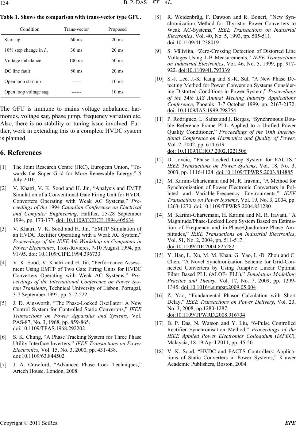
Table 1. Shows the comparison with trans-vector type GFU.
Condition Trans-vector Proposed
Start-up 60 ms 20 ms
10% step change in Idc 30 ms 20 ms
Voltage unbalance 100 ms 50 ms
DC line fault 80 ms 20 ms
Open loop start up ------ 10 ms
Open loop voltage sag ------ 10 ms
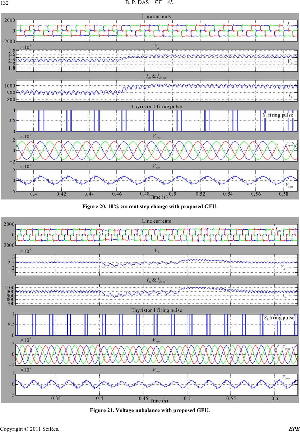
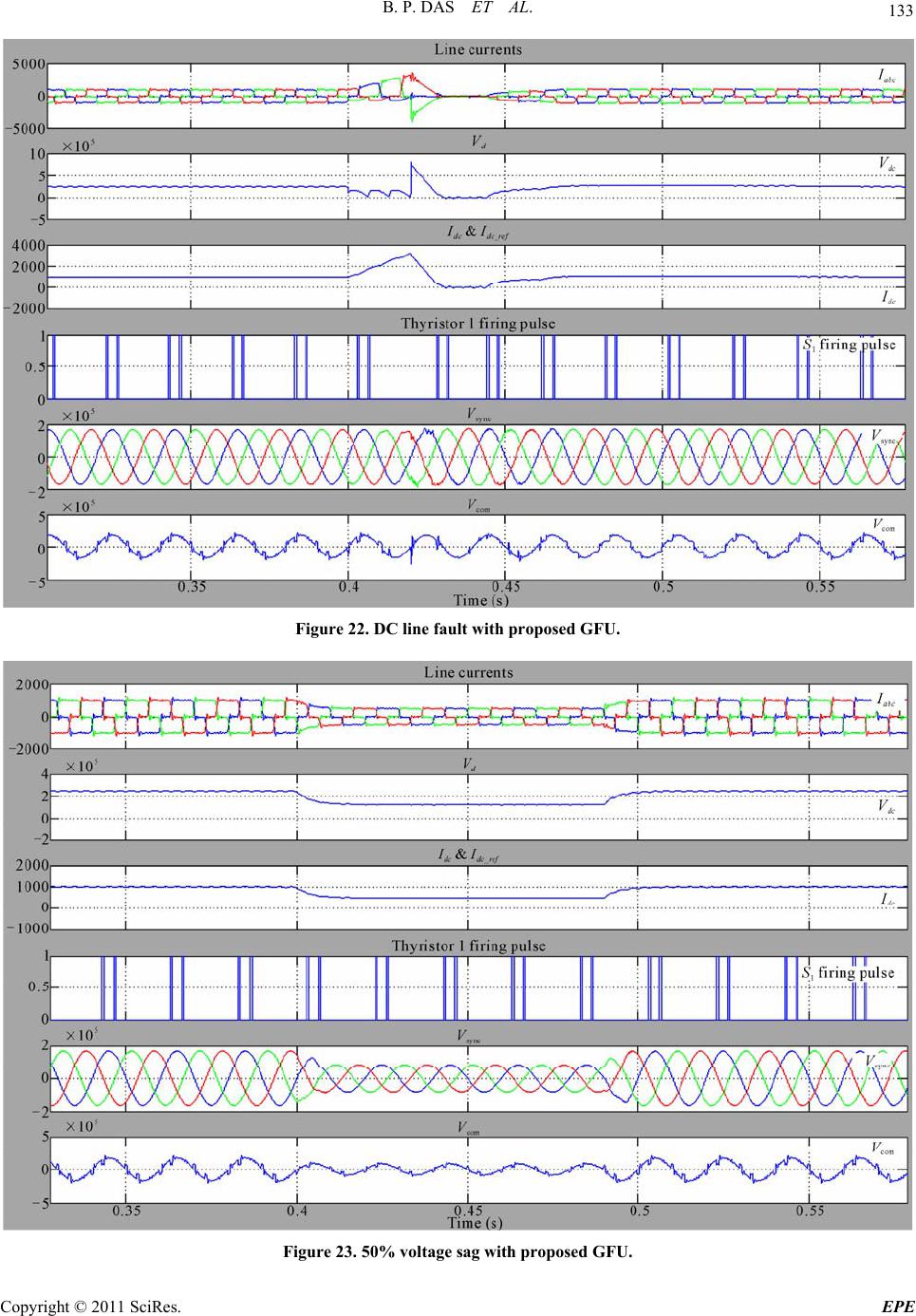
The GFU is immune to mains voltage unbalance, har-
monics, voltage sag, phase jump, frequency variation etc.
Also, there is no stability or tuning issue involved. Fur-
ther, work in extending this to a complete HVDC system
is planned.
6. References
[1] The Joint Research Centre (JRC), European Union, “To-
wards the Super Grid for More Renewable Energy,” 5
July 2010.
[2] V. Khatri, V. K. Sood and H. Jin, “Analysis and EMTP
Simulation of a Conventional Gate Firing Unit for HVDC
Converters Operating with Weak AC Systems,” Pro-
ceedings of the 1994 Canadian Conference on Electrical
and Computer Engineering, Halifax, 25-28 September
1994, pp. 173-177. doi: 10.1109/CCECE.1994.405634
[3] V. Khatri, V. K. Sood and H. Jin, “EMTP Simulation of
an HVDC Rectifier Operating with a Weak AC System,”
Proceedings of the IEEE 4th Workshop on Computers in
Power Electronics, Trois-Rivieres, 7-10 August 1994, pp.
91-95. doi: 10.1109/CIPE.1994.396733
[4] V. K. Sood, V. Khatri and H. Jin, “Performance Assess-
ment Using EMTP of Two Gate Firing Units for HVDC
Converters Operating with Weak AC Systems,” Pro-
ceedings of the International Conference on Power Sys-
tem Transients, Technical University of Lisbon, Portugal,
3-7 September 1995, pp. 517-522.
[5] J. D. Ainsworth, “The Phase-Locked Oscillator: A New
Control System for Controlled Static Convertors,” IEEE
Transactions on Power Apparatus and Systems, Vol.
PAS-87, No. 3, 1968, pp. 859-865.
doi:10.1109/TPAS.1968.292202
[6] S. K. Chung, “A Phase Tracking System for Three Phase
Utility Interface Inverters,” IEEE Transactions on Power
Electronics, Vol. 15, No. 3, 2000, pp. 431-438.
doi:10.1109/63.844502
[7] J. A. Crawford, “Advanced Phase Lock Techniques,”
Artech House, London, 2008.
[8] R. Weidenbrüg, F. Dawson and R. Bonert, “New Syn-
chronization Method for Thyristor Power Converters to
Weak AC-Systems,” IEEE Transactions on Industrial
Electronics, Vol. 40, No. 5, 1993, pp. 505-511.
doi:10.1109/41.238019
[9] S. Väliviita, “Zero-Crossing Detection of Distorted Line
Voltages Using 1-B Measurements,” IEEE Transactions
on Industrial Electronics, Vol. 46, No. 5, 1999, pp. 917-
922. doi:10.1109/41.793339
[10] S.-J. Lee, J.-K. Kang and S.-K. Sul, “A New Phase De-
tecting Method for Power Conversion Systems Consider-
ing Distorted Conditions in Power System,” Proceedings
of the 34th IAS Annual Meeting Industry Applications
Conference, Phoenix, 3-7 October 1999, pp. 2167-2172.
doi: 10.1109/IAS.1999.798754
[11] P. Rodriguez, L. Sainz and J. Bergas, “Synchronous Dou-
ble Reference Frame PLL Applied to a Unified Power
Quality Conditioner,” Proceedings of the 10th Interna-
tional Conference on Harmonics and Quality of Power,
Vol. 2, 2002, pp. 614-619.
doi: 10.1109/ICHQP.2002.1221506
[12] D. Jovcic, “Phase Locked Loop System for FACTS,”
IEEE Transactions on Power Systems, Vol. 18, No. 3,
2003, pp. 1116-1124. doi:10.1109/TPWRS.2003.814885
[13] M. Karimi-Ghartemani and M. R. Iravani, “A Method for
Synchronization of Power Electronic Converters in Pol-
luted and Variable-Frequency Environments,” IEEE
Transactions on Power Systems, Vol. 19, No. 3, 2004, pp.
1263-1270. doi:10.1109/TPWRS.2004.831280
[14] M. Karimi-Ghartemani, H. Karimi and M. R. Iravani, “A
Magnitude/Phase-Locked Loop System Based on Estima-
tion of Frequency and in-Phase/Quadrature-Phase Am-
plitudes,” IEEE Transactions on Industrial Electronics,
Vol. 51, No. 2, 2004, pp. 511-517.
doi:10.1109/TIE.2004.825282
[15] Y. Han, L. Xu, M. M. Khan, G. Yao, L.-D. Zhou and C.
Chen, “A Novel Synchronization Scheme for Grid-Con-
nected Converters by Using Adaptive Linear Optimal
Filter Based PLL (ALOF- PLL),” Simulation Modelling
Practice and Theory, Vol. 17, No. 7, 2009, pp. 1299-
1345. doi:10.1016/j.simpat.2009.05.004
[16] Z. Yao, “Fundamental Phasor Calculation with Short
Delay,” IEEE Transactions on Power Delivery, Vol. 23,
No. 3, 2008, pp.1280-1287.
doi:10.1109/TPWRD.2008.916734
[17] B. P. Das, N. Watson and Y. Liu, “6-Pulse Controlled
Rectifier Synchronisation Method,” Proceedings of the
IEEE Applied Power Electronics Colloquium (IAPEC),
Malaysia, 18-19 April 2011, pp. 45-50.
[18] V. K. Sood, “HVDC and FACTS Controllers: Applica-
tions of Static Converters in Power Systems,” Kluwer
Academic Publishers, Boston, 2004.