 Wireless Sensor Network, 2011, 3, 147-157 doi:10.4236/wsn.2011.35017 Published Online May 2011 (http://www.SciRP.org/journal/wsn) Copyright © 2011 SciRes. WSN 3D Localization and Tracking of Objects Using Miniature Microphones Radu Ionescu1, Riccardo Carotenuto1*, Fabio Urbani2 1DIMET, Università “Mediterranea” di Reggio Calabria, R eggio Calabri a , Italy 2Departme n t of Engineer ing, the University of Texas at Brownsville, Brownsville, USA E-mail: r.carotenuto@unirc.it Received March 1, 2011; revised April 1, 2011; accepted April 11, 2011 Abstract A system for accurate localization and tracking of remote objects is introduced, which employs a reference frame of four coplanar ultrasound sources as transmitters and miniature microphones that equip the remote objects as receivers. The transmitters are forced to emit pulses in the 17 - 40 kHz band. A central processing unit, knowing the positions of the transmitters and the time of flight of the ultrasound signals until they reach the microphones, computes the positions of the microphones, identifying and discarding possible false sig- nals due to echoes and environmental noise. Once the microphones are localized, the position of the object is computed by finding the placement of the geometrical reconstructed object that fits best with the calculated microphones positions. The operating principle of the localization system is based on successive frames. The data are processed in parallel for all the microphones that equip the remote objects, leading to a high repeti- tion rate of localization frames. In the proposed prototype, all the computation, including signal filtering, time of flight detection, localization and results display, is carried out about 25 times per second on a note- book PC. Keywords: Localization System, Remote Object, Tracking, Ultrasounds, Time of Flight 1. Introduction The increasing interest in systems able to provide users with remotely accessible capabilities (e.g. security, do- motics, health care, new generation of game consoles and video games, etc.) has encouraged the development of cheap and effective devices aimed at tracking objects and people within a certain space region. Accurate ob- jects localization and tracking is currently a challenging problem. Tracking is normally performed in the context of higher-level applications that require the location and/or shape of the object at every iteration or time in- stant. Difficulties in tracking objects can arise due to object masking by external obstacles or abrupt object motion. A visual approach using video cameras is employed in most applications, when objects localization and tracking is based either on color hystograms [1-3], illumination changes [4], occlusion [5-7], appearance [7,8] or scale variations [9]. Infrared techniques can also be applied [10-12]. An important drawback of video localization systems is that they cannot be us ed in many situations or environments due to the frequent blockage of the light by different obstacles and structures. Moreover, video lo- calization relies on the camera resolution, generally re- sulting in poor spatial resolution. A variety of techniques have been developed for lo- calization purpose, which are based on radio frequency (RF) [13,14]. Probably the most famous one is the Global Positioning System (G PS), but it does no t prov ide a sufficient resolution (order of meters) for some appli- cations such as precise localization of objects and per- sons, and it is not effective in most indoor environments or other areas with limited view of the sky. Another technique, Global System for Mobile communications (GSM), showed an uncertainty of tens to hundreds of meters in objects localization [15,16]. By employing 29 different GSM channels, a median accuracy ranging from 1.94 to 4.07 m was obtained in indoor objects lo- calization [17]. The use of Wireless Network Technolo- gies, such as Wi-Fi [18], Bluetooth [19], Wireless Local Area Networks (WLAN) [20,21] or ZigBee [22], did not achieve better localization accuracy. Ultra-Wide Band (UWB), Indoor GPS positioning and Radio Frequency  148 R. IONESCU ET AL. Identification (RFID) technology were also evaluated, providing an uncertainty in estimating mobile objects localization in the order of cm [20,23]. The sound source localization is based on determining the coordinates of sound sources in relation to a point in space. In a recent paper, sound source localization and tracking method using an array of eight microphones was proposed [24]. The method is based on a frequency-do- main implementation of a steered beamformer along with a particle filter-based tracking algorithm. Using an array of 8 microphones, a robot was able to follow a person speaking to it by estimating the direction where the speech sound was coming from. The localization accu- racy was around 1˚ within 1 m distance, both on azimuth and elevation, and around 1.4˚ within 3 m distance. The current location of another robot, using an array of 24 microphones distributed on two walls inside a close laboratory room, was based on robot speaking, and pro- duced an average localization error of about 7 cm close to the array and 30 cm far away from the array [25]. These are examples of active localization systems, in which the reference system is equipped with receivers placed at known locations, which estimate the distance to the remote device based on acoustic signals transmitted from the device. A similar strategy was employed in the case of the ac- tive Bat ultrasonic location system for people localiza- tion [26]. Small units called Bats, consisting of a radio transceiver, controlling logic and ultrasound transducer, are carried by persons. Ultrasound receiver units are placed at known positions on the ceiling of an indoor room. The times-of-arrival (TOA) of ultrasound from the Bat emitting device to each transducer are measured, and radio signals are used for synchronization. The location accuracy was below 10 cm. The 2D position of an automatic guided vehicle was obtained with an accuracy of a few mm from the time-of-flight (TOF) of ultrasound signals [27]. The lo- calization system employed consisted of ultrasound re- ception and emission beacons positioned at the same height on the docking workstation and on the automatic guided vehicle, respectively. The Massachusetts Institute of Technology has devel- oped the ‘Crick et’ indoor location system. ‘Cricket’ uses a combination of radio frequency (RF) and ultrasound signals to obtain the location of a remote device. Bea- cons placed on the walls and ceilings inside a building transmit a concurrent ultrasonic pulse on each RF adver- tisement. When this pulse arrives to listeners attached to the remote device, these estimate the distance to the cor- responding beacon by taking advantage of the difference in propagation speeds between RF and ultrasound. This method employs a passive localization system, in which the reference system is equipped with beacons placed at known locations that periodically transmit signals to the remote device equipped with receivers, which estimate the distances to the beacons. The Cricket beacons and listeners are identical hardware devices. The Cricket system could provide positioning precision between 1 and 3 cm [28]. Most 3D-localization systems based on ultrasound distance measurement use time-of-flight measurements which can be easily and cost-efficiently performed be- cause of the slow speed of ultrasound in air (about 343 m/s at 20˚C). These systems include either a few refer- ence beacons (minimum 3 or 4) equipped with ultra- sound transmitters to localize receiving devices, or vice versa, the localized device transmits an ultrasound signal received by several microphones belonging to a refer- ence systems. Transmitted ultrasound signals are realized as constant-frequency bursts or coded signals in a broader frequency band [29]. The principal advantages of a localization system with transmitters in fixed loca- tions and receiving sensor devices are that the device is able to compute its own position locally, and that the transmitters can send sign als synchronously [30,31]. Recently, we have presented promising preliminary results for very accurate objects localization and tracking, employing a new approach based on a passive localiza- tion system [32]. In this paper we show the capabilities and achievements of our system. It is quite different from the Cricket localization system, which is composed of complex and intelligent nodes that allow easy cellular management. The latter is useful especially in a multi-room environment, but it shows relatively low po- sitioning accuracy and rate. Moreover, the single node results quite big and not easily worn or placed on small objects. No applications employing the Cricket system were reported on gesture tracking and fine positioning, which in fact require localization rates in the order of tens of times per second and accuracy in the sub-centi- metric range. The localization system that we propose is much simpler both in construction and operation mode and, in perspective, well suited for future system-on-chip realizations. The proposed system employs a reference frame of ul- trasound sources as transmitters, and miniature micro- phones that equip the remote object as receivers. The distances between transmitters and receivers are esti- mated from the time-of-flight of the ultrasound signals. Ultrasound based time-of-flight methodology was proved to be more reliable and accurate than radio based ap- proaches [33]. Moreover, the use of ultrasound sources and miniature microphones reduce at a minimum both the audible and dimensional discomfort during system operation. Copyright © 2011 SciRes. WSN  R. IONESCU ET AL. 149 The paper is organized as follows: in the next section we describe the proposed system and its principle of op- eration, while in the following sections we present the realized prototype, the localization algorithm employed and the experimental results obtained in different appli- cations. 2. System Description and Principle of Operation The aim of the system that we developed is to ob tain the accurate localization and tracking of the movement of remote objects. The main elements of the system are a set of ultrasound sources and one or more receiving tar- gets. In our localization system, we employ tweeters as emitters, being the active elements of the system, and miniature microphones as receivers, which are the pas- sive elements of the system. The reference frame of the system is formed by four tweeters placed at known locations, specifically at the vertexes of a rectangle with the lengths of its sides a and b, respectively (Figure 1). The remote object is equipped with several miniature microphones mounted at strategic positions on the object, which are wired to a data acquisition board. Knowing the coordinates of the microphones and the geometry of the object, the shape of the object and its 3D orientation can be represented in any virtual context. The strategy that we propose is limited to devices that do not deform sig- nificantly their shape when they are manipulated. The operating principle of the localization system is based on successive frames. For locating the current po- sition, or tracking the movement of the remote object, the localization of each individual microphone at every Figure 1. The reference frame with four tweeters (repre- sented by triangles) and one microphone (represented by a circle). given time instants (i.e., localization frame) during sys- tem operation is necessary. Once determined the local- ization of the microphones, the position of the object is computed by finding the placement of the geometrical reconstructed object that better fits with the calculated microphones positions. The positions of the microphones are calculated in re- lation with th e origin point o f the reference frame, which for convenience was chosen to be the position of one of the four tweeters. During each localization frame, the tweeters emit, at predefined constant time intervals, ultrasonic pulses to- wards the remote object. These pulses, reaching the miniature microphones placed on the remote object, are acquired as electrical signals by the data acquisition board. The d istance l between each microphone and each one of the tweeters is indirectly estimated by a central proc- essing unit from the time of flight Tf employed by the ultrasound signal emitted by the tweeter to reach the mi- crophone, assuming the linearity of the wave propag atio n path and that the speed of sound v in a given transmis- sion medium is constant and its value is known (Equa- tion 1). An inherent delay introduced by the system components during signal propagation must be also taken into account. Thus, a constant offset distance loffset, whose value was experimentally measured, must be subtracted in order to obtain the correct distance between each pair microphone/tweeter: offset lvT l (1) The obtained distances are then used to calculate mi- crophones position s. For each microphone, the fo llowing four sphere equations that describe the distances between the microphone and the four tweeters forming the refer- ence frame can be written (Equation (2)): 2222 1 2 222 2 22 22 3 2 22 2 4 lxyz lxayz lxa ybz lxyb z (2) Resolving the four possible systems resulting from picking in all combination s only th ree equ ations at a time from the available four sphere equations, four values for the position of the microphone are determined: (x1, y1, z1), (x2, y2, z2), (x3, y3, z3) and (x4, y4, z4), respectively. Here, we should note that every syste m of three equations of (2) has two possible solutions, and a single solution is ob- tained by limiting to a half-space the valid region of op- eration for the remote device with respect to the refer- ence frame. Copyright © 2011 SciRes. WSN  150 R. IONESCU ET AL. If the estimation of the distances between the micro- phone and the four tweeters would be perfect, four iden- tical values for microphone position would be obtained. However, due to different disturbances (noise, echoes, obstacles, etc.), l1, l2, l3, l4 are generally affected by slight uncertainties. By computing the position of the given microphone as the mean value of the four positions cal- culated on each one of the three axes (Equation 3), any small errors occurred in calculating the position of the microphone are minimized. This represents an advantage provided the fact that we employ a reference frame formed by four tweeters, and not by only three tweeters that would have been otherwise sufficient for estimating the position of the microphone. 4 1 4 1 4 1 1 4 1 4 1 4 i i i i i i x y zz y (3 ) The robustness of the algorithm developed relies on a technique to discard any fake points, which could imply the failure of the correct localization of the object. For this purpose, the “distance” between all the four com- puted microphone positions is calculated, i.e. the square root of the sum of squares between every pair of two from the four computed microphone coordinates on each one of the three Cartesian axes (Equation 4): 44 4 222 11 1 1 12 ijij i i,j i,ji,j ij ijij Testx xyyz z j Miniature microphones: FG-6163 (Kn owles Acoustics, Itasca, Illinois, USA) is a condenser microphone of cylindrical shape, 2.6 mm length and diameter, 0.79 mm acoustical receiver window diameter, and 80 mg weight. The choice of a very small microphone comes as a nee d of our application. In the proposed localization system, the microphones are placed on the object whose localization is desired. Thus, they must not represent a discomfort, (4) If the parameter Test is higher than a set threshold value, the localization of the given microphone is con- sidered erroneous. However, the object can be super-described by em- ploying a higher number of miniature microphones than the strictly necessary one to represent its shape, e.g. 4 or more microphones for a parallelepiped. By doing this, any failure or error in the correct localization of one or more microphones will not compromise the accurate computation of the position of the object, provided that valid signals from the strictly necessary number of mi- crophones are still obtained. When the number of correctly localized microphones during a given localization frame is not enough in order to represent the shape of the object, the visualization of the object is skipped during that particular localization frame. However, because of the high repetition rate of localization frames achiev ed by the propo sed localizatio n system (Section 4), this rare undesirable event could eas- ily pass practically unnoticed even concerning applica- tions in which the object describes a fast movement. 3. Experimental Set-up The prototype of the proposed system is presented in Figure 2. The different components forming the proto- type are listed below: Processing unit: a PC is employed as central pro- cessing unit of the localization system. It uses algorithms written in Matlab (The MathWorksTM) both for building the acoustic pulses that are emitted by the tweeters, and for acquiring, storing and analyzing the signals received by the microphones. Data emission/acquisition board: MOTU 828 mk3 (MOTU, C ambri dge, M assachus etts, USA). It is p rovid ed with ten analog inputs and outputs that can operate at sample rates up to 192 kSamples/s. The PC connection is realized via FireWire. Tweeters: Sony MDR-EX33LKP (Sony Corporation, Japan). Preliminary tests performed have shown that this specific model is able to emit sufficiently accurate acoustic pulses in the chosen ultra-acoustic band. It fulfils furthermore our requirements regarding small size, while the diameter of its pressure output hole of only 3 mm ensures a wide emission lobe, well covering the space region of interest at aroun d 20 - 40 kHz. Figure 2. Photo of the localization system prototype. Copyright © 2011 SciRes. WSN 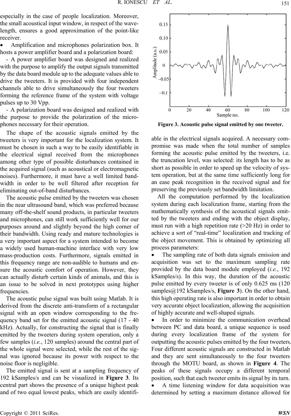 R. IONESCU ET AL. 151 especially in the case of people localization. Moreover, the small acoustical input window, in respect of the wave- length, ensures a good approximation of the point-like receiver. Amplification and microphones polarization box. It hosts a power amplifier board and a polarization board: - A power amplifier board was designed and realized with the purpose to amplify the output signals transmitted by the dat a board m odule up to t he adequate values able t o drive the tweeters. It is provided with four independent channels able to drive simultaneously the four tweeters forming the reference frame of the system with voltage pulses up to 30 Vpp. - A polarization board was designed and realized with the purpose to provide the polarization of the micro- phones necessary for their operation. The shape of the acoustic signals emitted by the tweeters is very important for the localization system. It must be chosen in su ch a way to be easily identifiable in the electrical signal received from the microphones among other type of possible disturbances contained in the acquired signal (such as acoustical or electromagnetic noises). Furthermore, it must have a well limited band- width in order to be well filtered after reception for eliminating o ut -o f-band disturbance s. The acoustic pulse emitted by the tweeters was chosen in the near u ltrasou nd b and , wh ich w as p r efer red b ecaus e many off-the-shelf sound products, in particular tweeters and microphones, can still work sufficiently well for our purposes around and slightly beyond the high corner of their bandwidth. Using ready and mature technologies is a very important aspect for a system intended to become a widely used human-machine interface with very low mass-production costs. Furthermore, signals emitted in this frequency range are non-audible to humans and en- sure the acoustic comfort of operation. However, they can actually disturb certain kinds of animals, and this is an issue to be solved in next prototypes using higher frequencies. The acoustic pulse signal was built using Matlab. It is derived from the discrete anti-transform of a rectangular signal with an open window corresponding to the fre- quency band set for the emitted acoustic signal (17 - 40 kHz). Actually, for constructing the signal that is finally emitted by the tweeters during system operation, only a few samples (i.e., 120 samples) around the cen tral par t of the whole signal were selected, while the rest of the sig- nal was ignored because its power with respect to the noise floor is negligible. The emitted signal is sent at a sampling frequency of 192 kSamples/s and can be visualized in Figure 3. Its central part shows the presence of a unique highest peak and of two equal lowest peaks, which are easily identifi- Figure 3. Acoustic pulse signal emitted by one tweeter. able in the electrical signals acquired. A necessary com- promise was made when the total number of samples forming the acoustic pulse emitted by the tweeters, i.e. the truncation level, was selected: its length has to be as short as possible in order to speed up the velocity of sys- tem operation, but at the same time sufficiently long for an ease peak recognition in the received signal and for preserving th e previously set bandwidth limitation. All the computation performed by the localization system during each localization frame, starting from the mathematically synthesis of the acoustical signals emit- ted by the tweeters and ending with the object display, must run with a high repetition rate (>20 Hz) in order to achieve a sort of “real-time” localization and tracking of the object movement. This is obtained by optimizing all process parameters: The sampling rate of both data signals emission and acquisition was set to the maximum sampling rate provided by the data board module employed (i.e., 192 kSamples/s). In this way, the duration of the acoustic pulse emitted by every tweeter is of only 0.625 ms (120 samples@192 kSamples/s, Figure 3). On the other hand, this high operating rate is also important in order to obtain very accurate object localization, allowing the acquisition of highly accurate and well-shaped signals. In order to minimize the communication overhead between PC and data board, a unique sequence is used during every localization frame of the system for outputting the acoustic pulses emitted by the four tweeters. Four different acoustic signals are constructed in Matlab and they are sent simultaneously to the four tweeters through the MOTU board, as shown in Figure 4. The peaks of these signals occupy a different temporal position, such that each tweete r emits its signal by its turn. A time listening window for data acquisition was determined by setting a maximum distance allowed for Copyright © 2011 SciRes. WSN 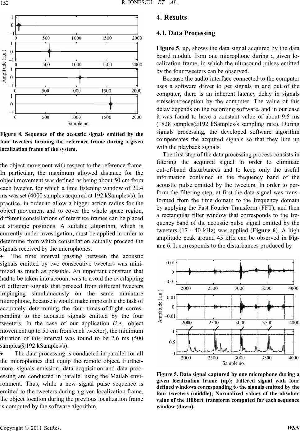 152 R. IONESCU ET AL. Figure 4. Sequence of the acoustic signals emitted by the four tweeters forming the reference frame during a given localization frame of the system. the object movement with respect to the reference frame. In particular, the maximum allowed distance for the object movement was defined as being about 50 cm from each tweeter, for which a time listening window of 20.4 ms was set (4000 samples acquired at 192 kSamples/s). In practice, in order to allow a bigger action radius for the object movement and to cover the whole space region, different constellations of reference frames can be placed at strategic positions. A suitable algorithm, which is currently under investigation, must be applied in order to determine from which constellation actually proceed the signals received by the microphones. The time interval passing between the acoustic signals emitted by two consecutive tweeters was mini- mized as much as possible. An important constrain that had to be taken into account was to avoid the overlapping of different signals that proceed from different tweeters impinging simultaneously on the same miniature microphone, because it would make im possible the task of accurately determining the four times-of-flight corres- ponding to the acoustic signals emitted by the four tweeters. In the case of our application (i.e., object movement up to 50 cm from each tweeter), the minimum duration of this interval was found to be 2.6 ms (500 sample s @1 92 kSamples/s). The data processing is conducted in parallel for all the microphones that equip the remote object. Further- more, signals emission, data acquisition and data proc- essing are conducted in parallel using the Matlab envi- ronment. Thus, while a new signal pulse sequence is emitted to the tweeters during a given localization frame, the object location during the previous localization frame is computed by the software algorithm. 4. Results 4.1. Data Processing Figure 5, up, shows the data signal acquired by the data board module from one microphone during a given lo- calization frame, in which the ultrasound pulses emitted by the four tweeters can be observed. Because the audio interface connected to the computer uses a software driver to get signals in and out of the computer, there is an inherent latency delay in signals emission/reception by the computer. The value of this delay depends on the recording software, and in our case it was found to have a constant value of about 9.5 ms (1828 samples@192 kSamples/s sampling rate). During signals processing, the developed software algorithm compensates the acquired signals so that they line up with the playback signals. The first step of the data processing process consists in filtering the acquired signal in order to eliminate out-of-band disturbances and to keep only the useful information contained in the frequency band of the acoustic pulse emitted by the tweeters. In order to per- form the filtering step, at first the data signal was trans- formed from the time domain to the frequency domain by applying the Fast Fourier Transform (FFT), and then a rectangular filter window that corresponds to the fre- quency band of the acoustic pulse signal emitted by the tweeters (17 - 40 kHz) was applied (Figure 6). A high amplitude peak around 45 kHz can be observed in Fig- ure 6. It corresponds to the disturbances produ ced by Figure 5. Data signal capture d by one microphone during a given localization frame (up); Filtered signal with four defined windows corresponding to the signals emitted by the four tweeters (middle); Normalized values of the absolute value of the Hilbert transform computed for eac h sequence window (down). Copyright © 2011 SciRes. WSN 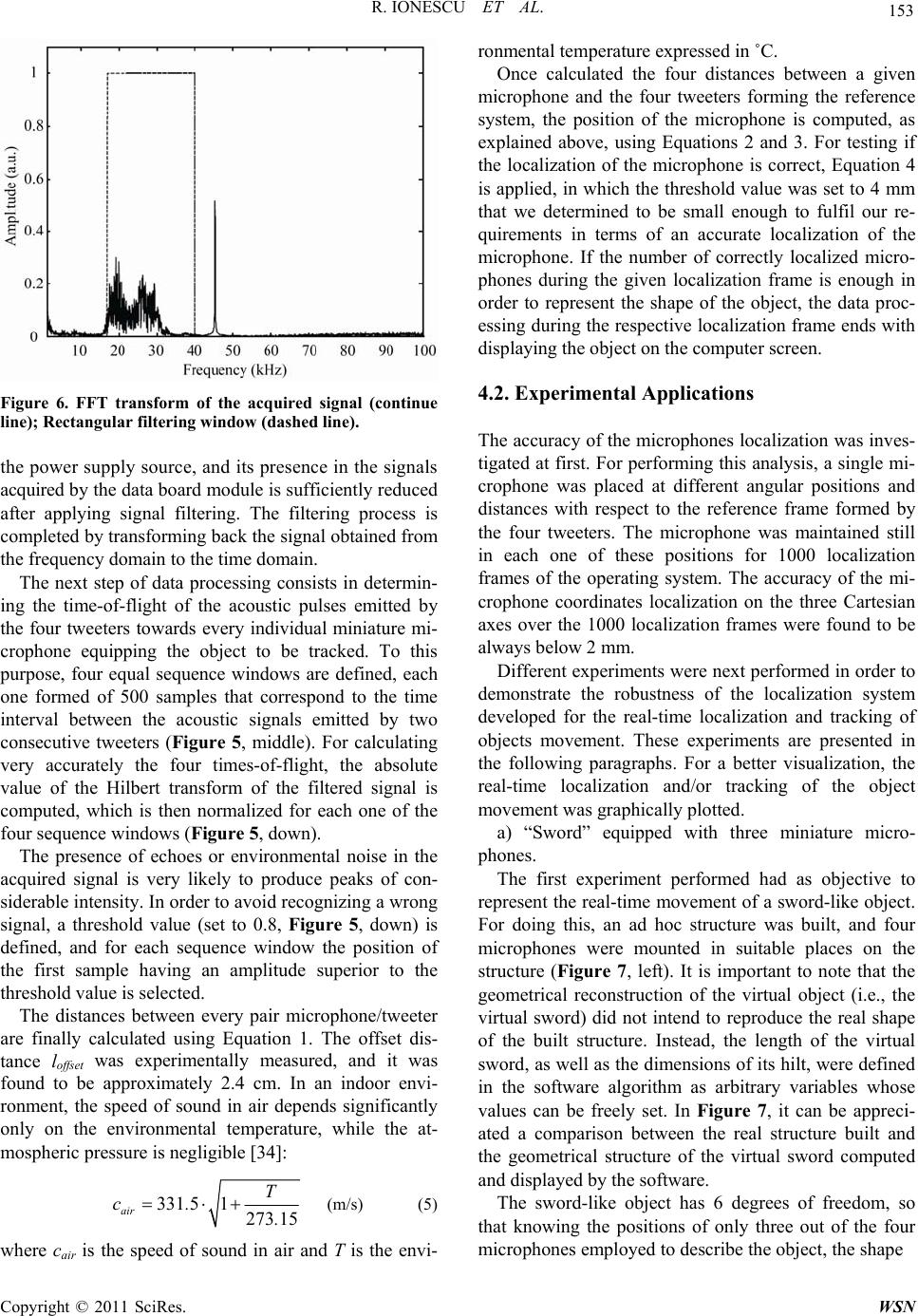 R. IONESCU ET AL. 153 Figure 6. FFT transform of the acquired signal (continue line); Rectangular filtering window (dashed line). the power supply source, and its presence in the signals acquired by the data board module is sufficiently reduced after applying signal filtering. The filtering process is completed by transforming back the signal obtained from the frequency domain to the time domain. The next step of data processing consists in determin- ing the time-of-flight of the acoustic pulses emitted by the four tweeters towards every individual miniature mi- crophone equipping the object to be tracked. To this purpose, four equal sequence windows are defined, each one formed of 500 samples that correspond to the time interval between the acoustic signals emitted by two consecutive tweeters (Figure 5, middle). For calculating very accurately the four times-of-flight, the absolute value of the Hilbert transform of the filtered signal is computed, which is then normalized for each one of the four sequ ence windows (Figure 5, down). The presence of echoes or environmental noise in the acquired signal is very likely to produce peaks of con- siderable intensity. In or der to avo id recognizin g a wr ong signal, a threshold value (set to 0.8, Figure 5, down) is defined, and for each sequence window the position of the first sample having an amplitude superior to the threshold value is selected. The distances between every pair microphone/tweeter are finally calculated using Equation 1. The offset dis- tance loffset was experimentally measured, and it was found to be approximately 2.4 cm. In an indoor envi- ronment, the speed of sound in air depends significantly only on the environmental temperature, while the at- mospheri c p ressure is n eg ligible [34]: 331 51273 15 air T c. . (m/s) (5) where cair is the speed of sound in air and T is the envi- ronmental temperature expressed in ˚C. Once calculated the four distances between a given microphone and the four tweeters forming the reference system, the position of the microphone is computed, as explained above, using Equations 2 and 3. For testing if the localization of the microphone is correct, Equation 4 is applied, in which the threshold value was set to 4 mm that we determined to be small enough to fulfil our re- quirements in terms of an accurate localization of the microphone. If the number of correctly localized micro- phones during the given localization frame is enough in order to represent the shape of the object, the data proc- essing during the respective localization frame ends with displaying the object on the computer screen. 4.2. Experimental Applications The accuracy of the microphones localization was inves- tigated at first. For performing this analysis, a single mi- crophone was placed at different angular positions and distances with respect to the reference frame formed by the four tweeters. The microphone was maintained still in each one of these positions for 1000 localization frames of the operating system. The accuracy of the mi- crophone coordinates localization on the three Cartesian axes over the 1000 localization frames were found to be always below 2 mm. Different experiments were next performed in order to demonstrate the robustness of the localization system developed for the real-time localization and tracking of objects movement. These experiments are presented in the following paragraphs. For a better visualization, the real-time localization and/or tracking of the object movement was graphically plotted. a) “Sword” equipped with three miniature micro- phones. The first experiment performed had as objective to represent the real-time movement of a sword-like object. For doing this, an ad hoc structure was built, and four microphones were mounted in suitable places on the structure (Figure 7, left). It is important to note that the geometrical reconstruction of the virtual object (i.e., the virtual sword) did not intend to reproduce the real shape of the built structure. Instead, the length of the virtual sword, as well as the dimensions of its hilt, were defined in the software algorithm as arbitrary variables whose values can be freely set. In Figure 7, it can be appreci- ated a comparison between the real structure built and the geometrical structure of the virtual sword computed and displayed by the software. The sword-like object has 6 degrees of freedom, so that knowing the positions of only three out of the four microphones employed to describe the object, the shape Copyright © 2011 SciRes. WSN 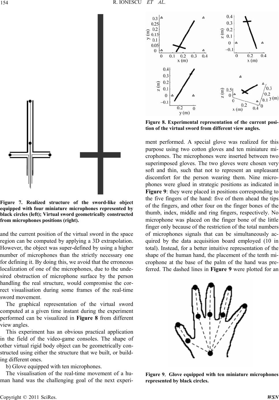 154 R. IONESCU ET AL. Figure 7. Realized structure of the sword-like object equipped with four miniature microphones represented by black circles (left); Virtual sword geometrically constructed from microphones positions (right). and the current po sition of the virtual sword in the space region can be computed by applying a 3D extrapolation. However, the object was super-defined by using a higher number of microphones than the strictly necessary one for defining it. By doing this, we avoid that the erroneous localization of one of the microphones, due to the unde- sired obstruction of microphone surface by the person handling the real structure, would compromise the cor- rect visualisation during some frames of the real-time sword movement. The graphical representation of the virtual sword computed at a given time instant during the experiment performed can be visualized in Figure 8 from different view angles. This experiment has an obvious practical application in the field of the video-game consoles. The shape of other virtual rigid body object can be geometrically con- structed using either the structure that we built, or build- ing different ones. b) Glove equipped with ten microphones. The visualisation of the real-time movement of a hu- man hand was the challenging goal of the next experi- Figure 8. Experimental representation of the current posi- tion of the virtual sword from different view angles. ment performed. A special glove was realized for this purpose using two cotton gloves and ten miniature mi- crophones. The microphones were inserted between two superimposed gloves. The two gloves were chosen very soft and thin, such that not to represent an unpleasant discomfort for the person wearing them. Nine micro- phones were glued in strategic positions as indicated in Figure 9: they were placed in positions corresponding to the five fingers of the hand: five of them ahead the tips of the fingers, and other four on the finger bones of the thumb, index, middle and ring fingers, respectively. No microphone was placed on the finger bone of the little finger only because of the restriction of the total numbers of microphones signals that can be simultaneously ac- quired by the data acquisition board employed (10 in total). Instead, for a better intuitive representation of the shape of the human hand, the placement of the tenth mi- crophone at the base of the palm of the hand was pre- ferred. The dashed lines in Figure 9 were plotted for an Figure 9. Glove equipped with ten miniature microphones represented by black circles. Copyright © 2011 SciRes. WSN 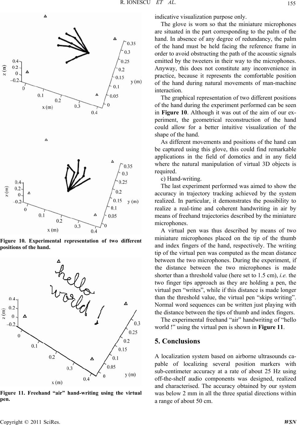 R. IONESCU ET AL. 155 Figure 10. Experimental representation of two different positions of the hand. Figure 11. Freehand “air” hand-writing using the virtual pen. indicative visualization purpose only. The glove is worn so that the miniature microphones are situated in the part corresponding to the palm of the hand. In absence of any degree of redundancy, the palm of the hand must be held facing the reference frame in order to avoid obstructing the path of the acoustic signals emitted by the tweeters in their way to the microphones. Anyway, this does not constitute any inconvenience in practice, because it represents the comfortable position of the hand during natural movements of man-machine interaction. The graphical representation of two different positions of the hand during the experiment performed can be seen in Figure 10. Although it was out of the aim of our ex- periment, the geometrical reconstruction of the hand could allow for a better intuitive visualization of the shape of t he hand. As different movements and positions of the hand can be captured using this glove, this could find remarkable applications in the field of domotics and in any field where the natural manipulation of virtual 3D objects is required. c) Hand-writing. The last experiment performed was aimed to show the accuracy in trajectory tracking achieved by the system realized. In particular, it demonstrates the possibility to realize a real-time and coherent handwriting in air by means of freehand trajectories described by the miniature microphones. A virtual pen was thus described by means of two miniature microphones placed on the tip of the thumb and index fingers of the hand, respectively. The writing tip of the virtual pen was computed as the mean distance between the two microphones. During the experiment, if the distance between the two microphones is made shorter than a threshold value (here set to 1.5 cm), i.e. the two finger tips approach as they are holding a pen, the virtual pen “writes”, while if this distance is made long er than the threshold value, the virtual pen “skips writing”. Normal word sequences can be written just playing with the distance between the tips of thumb and index fingers. The experimental freehand “air” handwriting of “hello world !” using t he virt ual pen i s show n in Fi gure 11. 5. Conclusions A localization system based on airborne ultrasounds ca- pable of localizing several position markers with sub-centimeter accuracy at a rate of about 25 Hz using off-the-shelf audio components was designed, realized and characterised. The accuracy obtained by our system was below 2 mm in all the three spatial d irections within a range of about 50 cm. Copyright © 2011 SciRes. WSN  156 R. IONESCU ET AL. Different experiments performed showed that the lo- calization system that we developed allows the real time localization and tracking of the movement of any remote object that does not deform significantly its shape when it is externally manipulated. The proposed system showed a positioning and trajectory tracking accuracy good enough to make it possible a straightforward reali- zation of a gestural interface, which is currently under investigation. At the best of the authors’ knowledge, in literature there are no similar localization systems, con- cerning localization rate and position accuracy. Very promising applications of the localization method here proposed are in the field of gestural interfaces, limb and body movement tracking for medical applications or video game consoles, just to name a few. Further work will consist in the implementation of wireless communication for the microphones. Higher frequencies, non-audible for the whole variety of living beings, will be used in the next prototypes employing custom transducers. 6. Acknowledgements R. Ionescu gratefully acknowledges a postdoctoral fel- lowship funded by the European Commission under the Marie Curie Transfer of Knowledge (TOK) Program (contract no. MTKD-CT-2006-042269). The authors gratefully acknowledge the support of Pentasonics S.r.l., Rome, Italy. 7. References [1] H. Zhou, Y. Yuan, Y. Zhang and C. Shi, “Non-Rigid Object Tracking in Complex Scenes,” Pattern Recogni- tion Letters, Vol. 30, No. 2, 2009, pp. 98-102. [2] Z. Zivkovic and B. Kröse, “An EM-Like Algorithm for Color-Histogram-Based Object Tracking,” Proceedings of the 2004 IEEE Computer Society Conference on Computer Vision and Pattern Recognition, Washington, 27 June-2 July 2004, pp. 798-803. doi:10.1109/CVPR.2004.1315113 [3] L. Peihua, “A Clustering-Based Color Model and Integral Images for Fast Object Tracking,” Signal Processing: Image Communication, Vol. 21, No. 8, 2006, pp. 676-687. doi:10.1016/j.image.2006.06.002 [4] S. Valette, I. Magnin and R. RémyProst, “Mesh-Based Video Objects Tracking Combining Motion and Lumi- nance Discontinuities Criteria,” Signal Processing, Vol. 84, No. 7, 2004, pp. 1213-1224. doi:10.1016/j.sigpro.2004.04.003 [5] D. Greenhill, J. Renno, J. Orwell and G. A. Jones, “Oc- clusion Analysis: Learning and Utilising Depth Maps in Object Tracking,” Image and Vision Computing, Vol. 26, No. 3, 2008, pp. 430-441. doi:10.1016/j.imavis.2006.12.007 [6] J. Jeyakar, R. V. Babu and K. R. Ramakrishnan, “Robust Object Tracking with Background-Weighted Local Ker- nels,” Computer Vision and Image Understanding, Vol. 112, No. 3, 2008, pp. 296-309. doi:10.1016/j.cviu.2008.05.005 [7] R. Marfil, L. Molina-Tanco, J. A. Rodríguez and F. Sandoval, “Real-Time Object Tracking Using Bounded Irregular Pyramids,” Pattern Recognition Letters, Vol. 28, No. 9, 2007, pp. 985-1001. doi:10.1016/j.patrec.2006.11.013 [8] M. S. Allili and D. Ziou, “Object Tracking in Videos Using Adaptive Mixture Models and Active Contours,” Neuro- computing, Vol. 71, No. 10-12, 2008, pp. 2001-2011. doi:10.1016/j.neucom.2007.10.019 [9] J. S. Hu, C. W. Juan and J. J. Wang, “A Spatial-Color Mean-Shift Object Tracking Algorithm with Scale and Orientation Estimation,” Pattern Recognition Letters, Vol. 29, No. 16, 2008, pp. 2165-2173. doi:10.1016/j.patrec.2008.08.007 [10] S. Colantonio, M. Benvenuti, M. G. Di Bono, G. Pieri and O. Salvetti, “Object Tracking in a Stereo and Infrared Vision System,” Infrared Physics & Technology, Vol. 49, No. 3, 2007, pp. 266-271. doi:10.1016/j.infrared.2006.06.028 [11] J. Shaik and K. M. Iftekharuddin, “Detection and Track- ing of Targets in Infrared Images Using Bayesian Tech- niques,” Optics & Laser Technology, Vol. 41, No. 6, 2009, pp. 832-842. doi:10.1016/j.optlastec.2008.11.007 [12] A. Treptow, G. Cielniak and T. Duckett, “Real-Time People Tracking for Mobile Robots Using Thermal Vi- sion,” Robotics and Autonomous Systems, Vol. 54, No. 9, 2006, pp. 729-739. doi:10.1016/j.robot.2006.04.013 [13] J. Zhoua and J. Shi, “Performance Evaluation of Object Localization Based on Active Radio Frequency Identifi- cation Technology,” Computers in Industry, Vol. 60, No. 9, 2009, pp. 669-676. doi:10.1016/j.compind.2009.05.002 [14] J. Song, C. T. Haas and C. H. Caldas, “A Proximity- Based Method for Locating RFID Tagged Objects,” Ad- van ced Engineering Informatics, Vol. 21, No. 4, 2007, pp. 367-376. doi:10.1016/j.aei.2006.09.002 [15] Laitinen, J. Lahteenmaki and T. Nordstrom, “Database Correlation Method for GSM Location,” Proceedings of the 53rd IEEE Vehicular Technology Conference, Rhodes, 6-9 May 2001, pp. 2504-2508. doi:10.1109/VETECS.2001.944052 [16] M. Berbineau, C. Tatkeu, J. P. Ghys and J. Rioult, “Lo- calisation de Véhicules en Milieu Urbain par GSM Oura- diogoniométrie Vehicle Self-Positioning in Urban Using or Radiogoniometer,” Recherche-Transports-Sécurité, Vol. 61, 1998, pp. 38-52. doi:10.1016/S0761-8980(98)90071-1 [17] A. Varshavsky, E. de Lara, J. Hightower, A. LaMarca and V. Otsason, “GSM Indoor Localization,” Pervasive and Mobile Computing, Vol. 3, No. 6, 2007, pp. 698-720. doi:10.1016/j.pmcj.2007.07.004 [18] M. Vossiek, L. Wiebking, P. Gulden, J. Wieghardt, C. Hoffmann and P. Heide, “Wireless Local Positioning,” Copyright © 2011 SciRes. WSN  R. IONESCU ET AL. Copyright © 2011 SciRes. WSN 157 IEEE Microwave Magazine, Vol. 4, No. 4, 2003, pp. 77-86. doi:10.1109/MMW.2003.1266069 [19] M. Lu, W. Chen, X. S. Shen, H. C. Lam and J. Liu, “Po- sitioning and Tracking Construction Vehicles in High Dense Urban Areas and Building Construction Sites,” Automation in Construction, Vol. 16, No. 5, 2007, pp. 647-656. doi:10.1016/j.autcon.2006.11.001 [20] H. M. Khoury and V. R. Kamat, “Evaluation of Position Tracking Technologies for User Localization in Indoor Construction Environments,” Automation in Construction, Vol. 18, No. 4, 2009, pp. 444-457. doi:10.1016/j.autcon.2008.10.011 [21] A. Huhtala, K. Suhonen, P. Mäkelä, M. Hakojärvi and J. Ahokas, “Evaluation of Instrumentation for Cow Posi- tioning and Tracking Indoors,” Biosystems Engineering, Vol. 96, No. 3, 2007, pp. 399-405. doi:10.1016/j.biosystemseng.2006.11.013 [22] X. Shen, W. Chen and M. Lu, “Wireless Sensor Net- works for Resources Tracking at Building Construction Sites,” Tsinghua Science & Technology, Vol. 13, Sup- plement 1, 2008, pp. 78-83. [23] B. S. Choi, J. W. Lee, J. J. Lee and K. T. Park, “Distrib- uted Sensor Network Based on RFID System for Local- ization of Multiple Mobile Agents,” Wireless Sensor Network, Vol. 3, 2011, pp. 1-9. doi:10.4236/wsn.2011.31001 [24] J. M. Valin, F. Michaud and J. Rouat, “Robust Localiza- tion and Tracking of Simultaneous Moving Sound Sources using Beamforming and Particle Filtering,” Ro- bot ics a nd Autonomous Systems, Vol. 55, No. 3, 2007, p p. 216-228. doi:10.1016/j.robot.2006.08.004 [25] Q. H. Wang, T. Ivanov and P. Aarabi, “Acoustic Robot Navigation Using Distributed Microphone Arrays,” In- formation Fusion, Vol. 5, No. 2, 2004, pp. 131-140. [26] A. Harter, A. Hopper, P. Steggles, A. Ward and P. Web- ster, “The Anatomy of a Context-Aware Application,” Wireless Networks, Vol. 8, No. 2-3, 2002, pp. 187-197. doi:10.1023/A:1013767926256 [27] F. Tong, S. K. Tso and T. Z. Xu, “A High Precision Ul- trasonic Docking System Used for Automatic Guided Vehicle,” Sensors and Actuators A: Physical, Vol. 118, No. 2, 2005, pp. 183-189. doi:10.1016/j.sna.2004.06.026 [28] A. Smith, H. Balakrishnan, M. Goraczko and N. Priyan- tha, “Tracking Moving Devices with the Cricket Location System,” 2nd International Conference on Mobile Sys- tems, Applications and Services, Boston, 6-9 June 2004. [29] H. Schweinzer and G. Kaniak, “Ultrasonic Device Local- ization and its Potential for Wireless Sensor Network Security,” Control Engineering Practice, Vol. 18, No. 8, 2010, pp. 825-86 2. doi:10.1016/j.conengprac.2008.12.007 [30] M. Hazas and A. Ward, “A Novel Broadband Ultrasonic Location System,” Proceedings of UbiComp 2002: 4th International Conference on Ubiquitous Computing, Lecture Notes in Computer Science, Goteborg, September 2002, pp. 264-280. [31] M. Hazas and A. Ward, “A High Performance Pri- vacy-Oriented location System,” Proceedings of the First IEEEInternational Conference on Pervasive Computing and Communications, Fort Worth, 23-26 March 2004, pp. 216-223. doi:10.1109/PERCOM.2003.1192744 [32] R. Carotenuto, R. Ionescu, P. Tripodi and F. Urbani, “Three Dimensional Gestural Interface,” 2009 IEEE Ul- trasonics Symposium, Rome, 20-23 September 2009, pp. 690-693. [33] L. Girod and D. Estrin, “Robust Range Estimation Using Acoustic and Multimodal Sensing,” Proceedings of 2001 IEEE/RSJ International Conference on Intelligent Robots and Systems, Maui, 29 October-3 November, 2001, pp. 1312-1320. doi:10.1109/IROS.2001.977164 [34] D. A. Bohn, “Environmental Effects on the Speed of Sound,” Journal of the Audio Engineering Society, Vol. 36, No. 4, 1988, pp. 223-231.
|