Paper Menu >>
Journal Menu >>
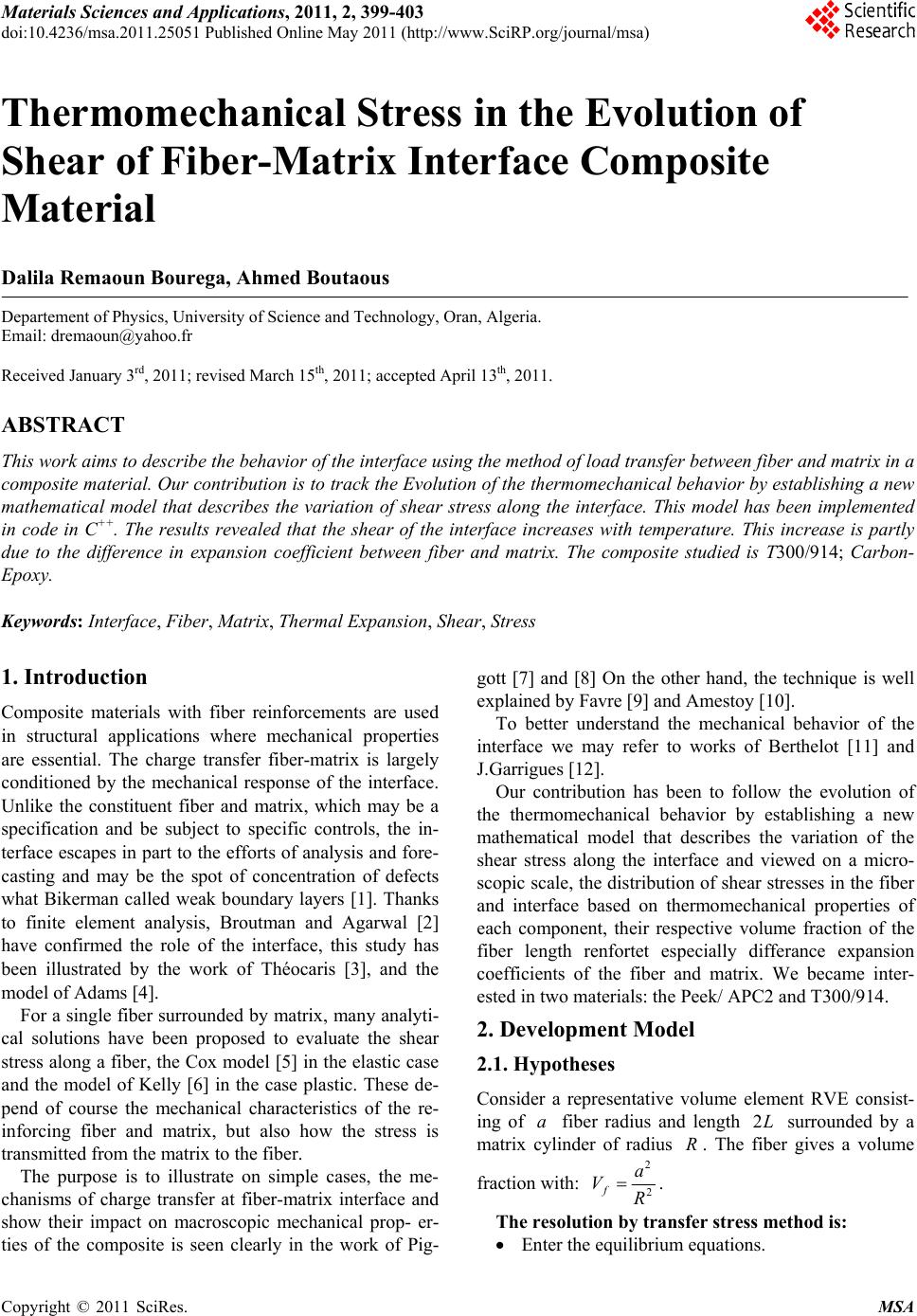 Materials Sciences and Applications, 2011, 2, 399-403 doi:10.4236/msa.2011.25051 Published Online May 2011 (http://www.SciRP.org/journal/msa) Copyright © 2011 SciRes. MSA 399 Thermomechanical Stress in the Evolution of Shear of Fiber-Matrix Interface Composite Material Dalila Remaoun Bourega, Ahmed Boutaous Departement of Physics, University of Science and Technology, Oran, Algeria. Email: dremaoun@yahoo.fr Received January 3rd, 2011; revised March 15th, 2011; accepted April 13th, 2011. ABSTRACT This work aims to describe the behavior of the interface using the method of load transfer between fiber and matrix in a composite material. Our contribution is to track the Evolution of the thermomechanical behavior by establishing a new mathematical model that describes the variation of shear stress along the interface. This model has been implemented in code in C++. The results revealed that the shear of the interface increases with temperature. This increase is partly due to the difference in expansion coefficient between fiber and matrix. The composite studied is T300/914; Carbon- Epoxy. Keywords: Inte rface, Fiber, Matrix, Thermal Expansion, Shear, Stress 1. Introduction Composite materials with fiber reinforcements are used in structural applications where mechanical properties are essential. The charge transfer fiber-matrix is largely conditioned by the mechanical response of the interface. Unlike the constituent fiber and matrix, which may be a specification and be subject to specific controls, the in- terface escapes in part to the efforts of analysis and fore- casting and may be the spot of concentration of defects what Bikerman called weak boundary layers [1]. Thanks to finite element analysis, Broutman and Agarwal [2] have confirmed the role of the interface, this study has been illustrated by the work of Théocaris [3], and the model of Adams [4]. For a single fiber surrounded by matrix, many analyti- cal solutions have been proposed to evaluate the shear stress along a fiber, the Cox model [5] in the elastic case and the model of Kelly [6] in the case plastic. These de- pend of course the mechanical characteristics of the re- inforcing fiber and matrix, but also how the stress is transmitted from the matrix to the fiber. The purpose is to illustrate on simple cases, the me- chanisms of charge transfer at fiber-matrix interface and show their impact on macroscopic mechanical prop- er- ties of the composite is seen clearly in the work of Pig- gott [7] and [8] On the other hand, the technique is well explained by Favre [9] and Amestoy [10]. To better understand the mechanical behavior of the interface we may refer to works of Berthelot [11] and J.Garrigues [12]. Our contribution has been to follow the evolution of the thermomechanical behavior by establishing a new mathematical model that describes the variation of the shear stress along the interface and viewed on a micro- scopic scale, the distribution of shear stresses in the fiber and interface based on thermomechanical properties of each component, their respective volume fraction of the fiber length renfortet especially differance expansion coefficients of the fiber and matrix. We became inter- ested in two materials: the Peek/ APC2 and T300/914. 2. Development Model 2.1. Hypotheses Consider a representative volume element RVE consist- ing of a fiber radius and length 2L surrounded by a matrix cylinder of radius R. The fiber gives a volume fraction with: 2 2 fa VR . The resolution by transfer stress method is: Enter the equilibrium equations. 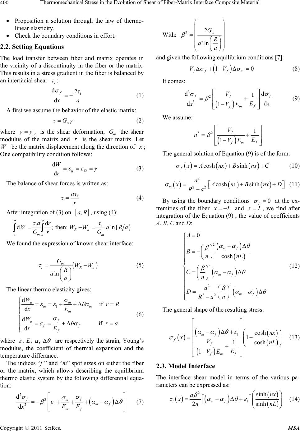 Thermomechanical Stress in the Evolution of Shear of Fiber-Matrix Interface Composite Material Copyright © 2011 SciRes. MSA 400 Proposition a solution through the law of thermo- linear elasticity. Check the boundary conditions in effort. 2.2. Setting Equations The load transfer between fiber and matrix operates in the vicinity of a discontinuity in the fiber or the matrix. This results in a stress gradient in the fiber is balanced by an interfacial shear i : d2 d fi x a (1) A first we assume the behavior of the elastic matrix: m G (2) where 12 is the shear deformation, m G the shear modulus of the matrix and is the shear matrix. Let W be the matrix displacement along the direction of x ; One compatibility condition follows: 12 d dij W r (3) The balance of shear forces is written as: i a r (4) After integration of (3) on ,aR, using (4): d d; then: ln RR ii Ra mmaa ar WWWaRa Gr G We found the expression of known shear interface: ln m iRa GWW R aa (5) The linear thermo elasticity gives: 1 d if d d if d m Rmm m f aff f WrR xE Wra xE (6) where , , , E are respectively the strain, Young’s modulus, the coefficient of thermal expansion and the temperature differance. The indices “f ” and “m” spot sizes on either the fiber or the matrix, which allows describing the equilibrium thermo elastic system by the following differential equa- tion: 221 2 d d ff mmf mf EE x (7) With: 22 ²ln m G R aa and given the following equilibrium conditions [7]: 10 fff m VV (8) It comes: 32 3 dd 1 d d1 f ff f fm V Ex xVE (9) We assume: 22 1 1 f f fm V nE VE The general solution of Equation (9) is of the fo rm: cosh sinh f x AnxBnxC (10) 2 22cosh sinh ma x AnxBnxD Ra (11) By using the boundary conditions 0 f at the ex- tremities of the fiber x L and x L, we find after integration of the Equation (9) , the value of coefficients A, B, C and D: 2 2 2 2 22 0 cosh mf mf mf A BnnL Cn a Dn Ra (12) The general shape of the resulting stress: 1cosh 1cosh 1 1 mf ff f fm nx xVnL E VE (13) 2.3. Model Interface The interface shear model in terms of the various pa- rameters can be expressed as: 2 1 sinh 2sinh imf nx a xnnL (14)  Thermomechanical Stress in the Evolution of Shear of Fiber-Matrix Interface Composite Material Copyright © 2011 SciRes. MSA 401 After variable change: 2 2 l x X lL ; We have: 2 1 sinh 2 2sinh 2 imf l nX a Xl nn (15) For 0X; The shear is maximal: 2 max1 tanh 22 mf anl n (16) 2.4. Isothermal Case and Comparison with the Cox Model To understand the shear model of the interface expressed by (16) It would be interesting to see the isothermal case by asking: 0 . It comes: 2 1max 1tanh . 22 anl n (17) It is at near constant the Cox model [6]. 2.5. Development of the Cox Model Consider a representative volume element RVE consist- ing of a fiber radius and length 2L surrounded by a matrix cylinder of radius R [9]. We apply the direction parallel to fibers (longitudinal direction) uniaxial traction 11 0 . Every direction normal to the fibers is called transverse direction. The law of elasticity applied to isotropic elastic ma- terial is written: trace 2 1 (18) With , Lame constants and , are respec- tively the tensors of stress and strain Inversely: 1trace EE 1 (19) then: 00 00 00 E E E where: 2 and f EE. This explains the existence of a transverse strains where the shear stresses and in the matrix and interface respectively. The method of load transfer between fiber and matrix [8] and [9], gives: 1 11 1 sh 2 2ch 2 f l x Ea xl (20) with: 2 12 2 ln m f G R Ea a 1 11 0th 22 l a (21) A near constant, the two expressions shear (17) and (21) are the same. 3. Results and Discussion We were interested at T300/914 carbon epoxy com- posite with known mechanical properties and a well de- fined fiber length; the variable parameters are the tem- perature and the volume fiber fraction, taking into ac- count the considerable difference of thermal expansion coefficients of the fiber and matrix. Figure 1 shows the shearing of the interface corres- ponding to the thermomechanical model which we have accomplished in Subsection 2.3, while Figure 2 and Figure 3 represent the Cox model we developed in Subsection 2.5. The Figure 1 allows us to conclude and compare; shear increases with temperature and our model is con- sistent with Cox model. The Figure 2 and Figure 3 indeed, in the Cox model [7] the shear varies with the deformation applied, we have shown it for the two different materials Peek/APC2 (Fig- ure 2) and Carbone-epoxy T300/914 (Figure 3). We note that the shear strength of fiber-matrix interface is 4000 MPa at the extremity of Peek, while of carbon epoxy is 3500 MPa for a strain and for the same length of fiber. We find that our model describes the behavior of the interface; the comparison with the Cox model is the proof. The Figure 4 shows the influence of temperature on the stress for a fixed fraction at 10% and the Figure 5 shows the influence of fiber volume fraction on the stress  Thermomechanical Stress in the Evolution of Shear of Fiber-Matrix Interface Composite Material Copyright © 2011 SciRes. MSA 402 Figure 1. Influence of temperature on the shear interface. Figure 2. Shear interface of Peek. for a fixed temperature to 140˚. 4. Conclusions It is well known that the composite mechanical behavior Figure 3. Shear interface of T300/914. strongly depends on the fiber-matrix interface. This in- terface is accessible only indirectly through the behave- ior it engenders in the composite or those attributed to it. The mechanical behavior of the interface depends on  Thermomechanical Stress in the Evolution of Shear of Fiber-Matrix Interface Composite Material Copyright © 2011 SciRes. MSA 403 Figure 4. Influence of temperature on the stress. Figure 5. Influence of volume fraction on the stress. several parameters of their components, fiber and matrix. We found that there is a greater influence of the tem-perature on the fiber-matrix interface behavior. We be- lieve that the volumic fraction of reinforcement has a greater contribution. This work shows that the percentage and the fiber type must be defined as they play a major role in the interface behavior of composite structures. REFERENCES [1] J. Bikerman, “The Science of Adhesive Joints,” Aca- demic Press, Inc, New York & London, 1968, p. 258. [2] L. J. Broutman and B. D. Agarwal, “Theoretical Study of the Effect of an Interfacial Layer on the Properties of Po- lymer,” Engineering & Science, Vol. 14, No. 8, 1974, pp. 581-588. [3] P. S. Theocaris, “The Unfolding Model for the Repre- sentation of the Mesophase Layer in Composites,” Jour- nal of Applied Polymer Science, Vol. 30, No. 2, 1985, pp. 621-645. doi:10.1002/app.1985.070300214 [4] D. F. Adams, “Micromechanical Predictions/Experimen- tal Correlations of the Influence of the Interface on the Mechanical and Plysical Properties of a Unidirectional Composite,” Composite Interfaces, Cleveland, 27-30 May 1986, pp. 351-365. [5] H. L. Cox, “The Elasticity and Strength of Paper and Other Fibrous Materials,” British Journal of Applied Physics, Vol. 3, No. 3, 1952, pp. 72-79. doi:10.1088/0508-3443/3/3/302 [6] A. Kelly and W. R. Thyson, “Fiber Strengthened Materi- als,” In: V. F. Zackay, Ed., High Strength Materials, John Wiley & Sons, London, 1964, pp. 578-602. [7] M. R. Piggott, “How the Interface Controls the Proprie- ties of Fibre Composites,” Progress in Science and Engi- neering of Composites: Proceedings of the 4th Interna- tional Conference on Composite Materials, Tokyo, 25-28 October 1982, pp. 193-202. [8] M. R. Piggot, “Debonding and Friction at Fibre-Polymer Interfaces. I: Criteria for Failure and Sliding,” Compos- ites Science and Technology, Vol. 30, No. 4, 1987, pp. 295-306. doi:10.1016/0266-3538(87)90017-0 [9] J. P. Favre, “Interface dans les composites fibreux,” Technique de l’Ingenieur, Traité Plastiques et Compo- sites, Vol. AM6, No. A7765, Article ID A7765, pp. 1-21. [10] M. Amestoy, “Introduction à la Mécanique des Milieu Déformables,” Ecole des mines de Paris, Paris, 1995. [11] J. M. Berthelot, “Matériaux Composites, Comportement Mécanique et Analyse des Structures,” Hermès-Lavoisier, Paris, June 2005. [12] J. Garrigues, “Fondements de la Mécanique des Milieux Continus,” Lavoisier, Paris, 2007. |