Journal of Applied Mathematics and Physics, 2014, 2, 443-448
Published Online May 2014 in SciRes. http://www.scirp.org/journal/jamp
http://dx.doi.org/10.4236/jamp.2014.26054
How to cite this paper: Gong, J., Yao, D.P. and Liu, X.H. (2014) Aerodynamic Optimization of the Expansion Section in a
Hypersonic Quiet Nozzle Based on Favorable Pressure Effect. Journal of Applied Mathematics and Physics, 2, 443-448.
http://dx.doi.org/10.4236/jamp.2014.26054
Aerodynamic Optimization of the Expansion
Section in a Hypersonic Quiet Nozzle Based
on Favorable Pressure Effect
Jian Gong, Dapeng Yao*, Xunhua Liu
China Academy of Aerospace Aerodynamics, Beijing, 100 074, China
Email: *ivezaku @gmail.co m
Received March 2014
Abstract
Maximum expansion angle is the primary p ar am e te r for the design of expansion section of hype r-
sonic quiet nozzle. Accord ing to the qu ant ity of maximum expansion angle, expansion section
could be classified as fast expansion and slow expansion. In order to diminish the effect of insta-
bility of Görtler vortex, gradually, slow expansio n was employed for quiet nozzle design. Based on
the favorable pressure effect, the maximum ex pans ion angle is optimized in this paper, and a con-
siderable selective session of maximum expansion angle is obt ained . The trend that slow expan-
sion is employed instead of fast ex pansio n is explained, and a new method is established for aero-
dynamic optimization of expansion section contour in a quiet nozzle.
Keywords
Quiet Nozzle, Maximum Expansion Angle, Favorable Pressure Effect
1. Introduction
A larger maximum expansion angle was employed in the design of quiet nozzle in the past [1]. In the early
1970s, a Mach 5 quiet nozzle [2] of which the maximum expansion angle was 22.6˚, was preliminarily devel-
oped for a leading tunnel at NASA LRC (Langley Research Center). A Mach 3.5 2D quiet nozzle [3] was de-
veloped from late 1970s to early 1980s, and its maximum expansion angle of upper surface was 28.75˚.
In the early 1990s, a Mach 6 quiet nozzle [4] with a maximum expansion angle of 9.84˚, was developed at
NASA LRC by employing slow expansion. And in late 1990s, a quiet nozzle with slower expansion was devel-
oped at Purdue University [5], and its maximum expansion angle was down to 4˚. A Mach 4 quiet nozzle with a
maximum expansion angle of 15˚ was developed by Zhou Yongwei and Yi Shihe [6] at National University of
Defense Technology in 2011. In the course that the fast expansion used in the prior study was gradually replaced
by slow expansion in the later term, the knowledge of primary factors for quiet nozzle boundary layer stability
was improved [7]. The occurrence of Görtler vortex instability could be delayed by slow expansion [8]. It was
noted by Beckwith [9] that the Görtler vortex instability in a contoured nozzle is the main factor of flow insta-
*Corresponding author.
J. Gong et al.
444
bility when Mach number is larger than 2.5, and it could be efficiently retarded by slow expansion. It was also
suggested that favorable pressure should be considered in the analysis of nozzle boundary layer stability.
In the design of Mach 6 quiet nozzle by Schneider [10], quiet flow condition could be met for both nozzles
(one is 240 mm in diameter of exit and 2.56 m in length, while the other one is 600 mm in diameter of exit and
10.36 m in length) with a maximum expansion angle of 4˚, using eN transition estimation at a certain unit Rey-
nolds number. However, the result of this semi-theoretic method should be calibrated in wind tunnel tests. Thus,
a concept of favorable pressure effect is utilized to study the effect of maximum expansion angle on the pressure
gradient on the wall along flow in this paper.
2. Computation Condition
To study the effect of maximum expansion angle on the flow field, 7 contours of axial symmetric nozzle with
different maximum expansion angles are designed for comparison. According to the improvement of maximum
expansion angle, 7 maximum expansion angles between 3˚ and 15˚ are selected for analysis. All the nozzlesare
the same in diameter of exit and Mach number. The main designed configuration parameters of those expansion
sections of nozzles are listed in Table 1. It is clear that the length of expansion section increase with maximum
expansion angle.
Those 7 contours are also shown in Figure 1. The throat of each nozzle is smoothly connected to the un-
iformed contraction section. It is clear that the radius of throat is determined with given Mach number and di-
ameter of exit, while the length of expansion section varies with the maximum expansion angle. The points
plotted in Fi gure 2 show the regularity that the length of expansion section decreases with increasing maximum
expansion angle.
Figure 2 only describes the relationship between the length of expansion section and maximum expansion
angle discretely, and a function in the form of Ltgθ could be introduced to demonstrate that in Figure 3. From
Figure 1. The contours of different axial symmetric nozzle.
Table 1. Configuration parameters of axial symmet ric nozzles with the exit Mach number of 6.
expansion angle radius of throat diameter of exit length of expansion section length of contraction section
3 19.472 300 3976.844 1200
4 19.472 300 3186.006 1200
6 19.472 300 2400.502 1200
8 19.472 300 2007.019 1200
10 19.472 300 1771.169 1200
12 19.472 300 1621.662 1200
15 19.472 300 1464.190 1200
J. Gong et al.
445
Figure 2. The relationship between the length of expansion section and max-
imum expansion angle.
Fig ure 3. L tg θ varies as a function of max imum expansion angle.
the fitted line, it is noted that Ltgθ is linear to the maximum expansion angle θ. The function can be described
as:
Ltgk b
θθ
= +
(1)
where, k and b are coefficients of the equation.
Substituting the data in Table 1 into the equation above and using least square fit, the coefficients are deter-
mine d :
15.326 158.734Ltg
θθ
= +
(2)
The relationship between the length of expansion section and maximum expansion angle is defined by this
equation. Thus, one of those two terms can be estimated using this equation in nozzle design given that the
quantity of the other is determined. Additionally, a too long nozzle will lead two negative results: the increased
difficulty in machining the inner surface and the easier transition in the boundary layer of nozzle wall cause by
T-S instability. Thus, the value of maximum expansion angle should not be selected too small.
3. Flow Field Computation
Flow fields near the throats of nozzles with different maximum expansion angle are shown in F igure 4. It is
noted that the change of pressure gradient becomes faster in the downstream flow field when maximum expan-
sion angle increases, given the same contraction section. Although all the nozzles finally provide flow of good
unifo r mi t y, it is critical to keep pressure gradient changing slowly for quiet nozzle.
The relationship between the distance that a point with a certain Mach number longitudinally departs from
throat and maximum expansion angle is shown in Fi gure 5. The longitudinal gradient of Mach number increases
with maximum expansion angle.
J. Gong et al.
446
(a) (b) (c)
(d) (e) (f) (g)
Figure 4. Mach number contours around the throat for various maximum expansion angle. (a) θ = 3˚; (b) θ = 4˚; (c) θ = 6˚;
(d) θ = 8˚; (e) θ = 10˚; (f) θ = 12˚; (g) θ = 15˚.
Fig ure 5. The relationship between the distance that
a point with a certain Mach number longitudinally
departs from throat and maximu m expansion angle.
The distributions of Mach number at nozzle exit in the condition of different maximum expansion angles are
shown in F igure 6. The flow field at exit for each maximum expansion angle is of good uniformity. The distri-
bution of downstream pressure on the inner wall of each nozzle is shown in Figur e 7. Generally, the pressure on
the wall continues to decrease, demonstrating that flow field near the wall in the nozzle is in a status of favorable
pressure. The decreasing increscent of pressure on throat wall increases with maximum expansion angle. For the
design of nozzle contour, this favorable pressure indicates the increase of initial force in the flow, which would
diminish the strength and propagation of disturbance, and eventually help prevent the transition of boundary
layer.
Based on the results given by Figure 7, the distributions of downstream pressure gradients on the walls in the
whole range of contoured nozzles are shown in Figure 8. It is noted that the distributional differences are mainly
in the area near the throat. Thus, the distributions of pressure gradients on the walls near the throat are demon-
strated in Figur e 9.
Figure 8 shows that downstream pressure gradients are all minus, further indicating the fact that pressures on
the walls continue to decrease. Also, peak values of downstream pressure gradients on the walls, which mean
most significant changes in pressure, are reached near the throats.
J. Gong et al.
447
Figure 6. The distributions of Mach number at nozzle exit for
various maximum expansion angle.
Figure 7. The distributions of static pressure on the nozzle wall.
Figure 8. The streamwise distribution of static pressure on the nozzle wall.
Figure 9. The distribution of pressure gradient on the nozzle wall for
various maximum expansion angle.
J. Gong et al.
448
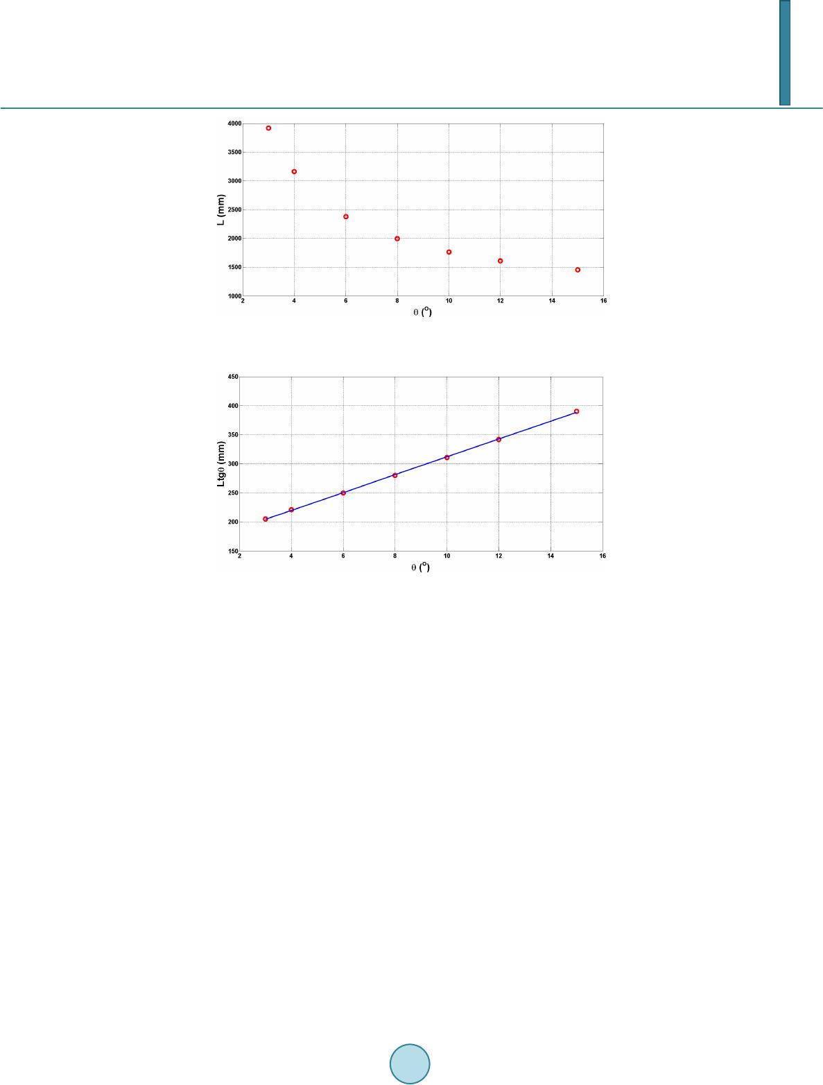
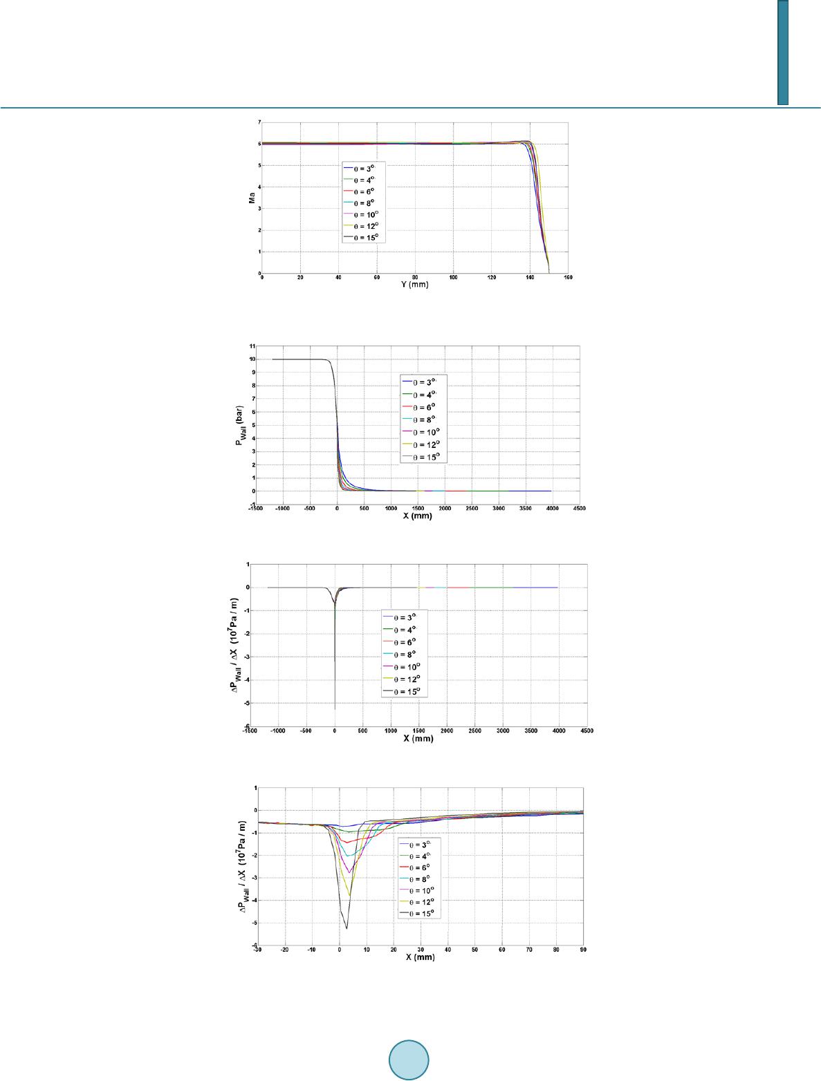
As shown in Figure 9, in the range 3 - 5 mm downstream from throat, peak values of downstream pressure
gradients are reached for all the nozzles with different maximum expansion angles. The absolute value of peak
pressure gradient decreases with maximum expansion angles, indicating that the change of wall pressure be-
comes mitigated. Because it is convex wall for nozzle flow near the throat, the low favorable pressure drives
flow moving downstream steady rather than rapid expansion which would lead to oscillation in flow and nozzle
wall.
4. Conclusion
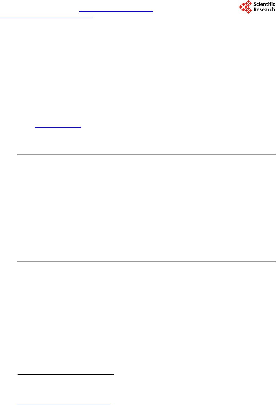
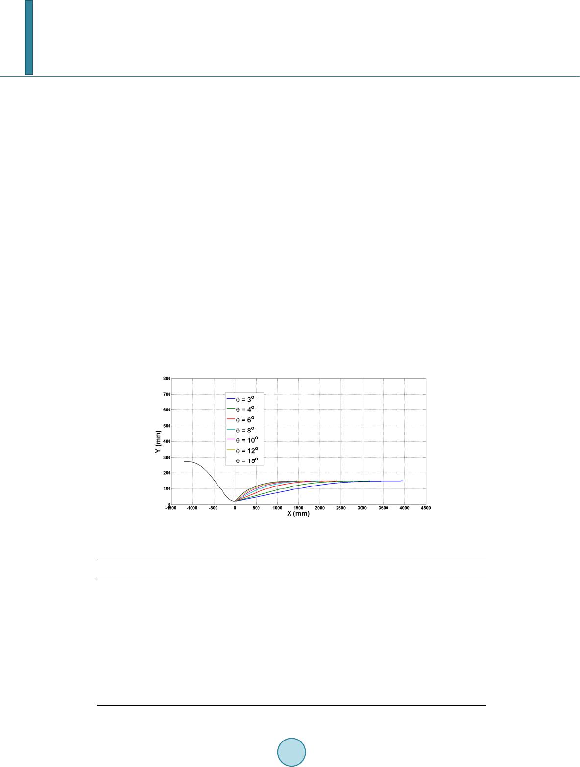
It can be concluded that a lower maximum expansion angle is required for quiet nozzle. However, a too low
value is also unfeasible because it may lead to extremely long nozzle consisting of more sections. Specifically, if
the maximum expansion angle is set as 3˚, a 4 m long expansion section which must be divided into more than
10 sections would be required (the 4˚ quiet nozzle at Purdue University is 2.56 m long and consists of 8 sec-
tions). Difficulties would be encountered in machining to meet the requirement of low roughness and smooth
joint. in another words, maximum expansion angle should be neither too large nor too small, and a optimized
value is to be determined. According to the discussion in the previous part, a optimized range of maximum ex-
pansion angle is 4˚ - 6˚. The fact that the maximum expansion angle of the Mach 6 quiet nozzle (the longest
nozzle all over the world) designed by Schneider is 4˚, agrees with our analysis.
References
[1] Beckwith, I.E. (1975) Development of a High Reynolds Number Quiet Tunnel for Transition Research. AIAA Journal,
13, 300-306. http://dx.doi.org/10.2514/3.49695
[2] Anders, J.B., Stainback, P.C. and Beckwith, I.E. (1978) A New Technique for Reducing Test Section Noise in Super-
sonic Wind Tunnels. AIAA Paper: 1978-0817.
[3] Beckwith, I.E. and Moore, W.O. (1982) Mean Flow and Noise Measurements in a Mach 3.5 Pilot Quiet Tunnel. AIAA
Paper: 1982-0569.
[4] Ch en, F.J., Wilkinson, S.P. and Beckwith, I.E. (1991) Görtler Instability and Hypersonic Quiet Nozzle Design. AIAA
Paper: 1991-1648.
[5] Schneider, S.P. (1998) Design and Fabrication of a 9.5-inch Mach-6 Quiet-Flow Ludwieg Tube. AIAA Paper:
1998-2511.
[6] Zhou, Y.W., Chang, X.Y., Yi, S.H. and Zhang, Y. (2002) The Aerodynamic Design of Supersonic Quiet Wind Tunnel.
Experiments and Measurements in Fluid Mechanics, 16, 61-66.
[7] Schneider, S.P. (2008) Development of Hypersonic Quiet Tunnels. Journal of Spacecraft and Rockets, 45, 641-664.
http://dx.doi.org/10.2514/1.34489
[8] Zhou, Y.W. and Yi, S.H. (2010) Summarization of the Characteristics and Development of Hypersonic Quiet Wind
Tunnel. Journal of Experimental Mechanics, 25, 167-172.
[9] Beckwith, I.E. and Holley, B.B. (1981) Görtler Vortices and Transition in Wall Boundary Layers of Two Mach-5 Noz-
zles. NASA -TP-1869.
[10] Schneider, S.P. (1998) Design of a Mach-6 Quiet-Flow Wind-Tunnel Nozzle Using the eN Method for Transition Es-
timation. AIAA Paper: 1998-0547.