Journal of Applied Mathematics and Physics, 2014, 2, 304-309
Published Online May 2014 in SciRes. http://www.scirp.org/journal/jamp
http://dx.doi.org/10.4236/jamp.2014.26036
How to cite this paper: Kaman, M.O., Celik, N. and Karakuzu, S. (2014) Numerical Stress Analysis of the Plates Used to Treat
the Tibia Bone Fracture. Journal of Applied Mathematics and Physics, 2, 304-309.
http://dx.doi.org/10.4236/jamp.2014.26036
Numerical Stress Analysis of the Plates Used
to Treat the Tibia Bone Fracture
M. O. Kaman, N. Celik, S. Karakuzu
Department of Mechanical Engineering, Firat University, 23119, Elazig, Turkey
Email: mka man @fira t. edu .tr , nevincelik23 @gmai l.com
Received N ove mber 20 13
Abstract
Tibial fractures are one of the most frequent bone fractures caused by accidents or falls because of
the tibia’s slender shape. In the tibial fractures close to the joint surface, a plate and screws may be
the ideal method of fixation. While using the plate and the screws the estimation of the stress on
the plate and screw gains importance before beginning the treatment. In this study, it is aimed to
conduct a numerical simulation which uses finite element methodology, to estimate the von Mises
stress subjected to the plate and screw which is used in tibia fracture treatment. A titanium plate
and 4 screws on it are used for treatment of the fracture. The fracture angle varies as 0˚, 15˚, 30˚,
and 45˚. The compressive force affected on the plate is estimated to be 750 N. Moreover, the bone
is simulated 3D, by using commercial software, ANSYS Structural.
Keywords
Tibia Fr actu r e, Finite Element Model, A NS YS , Biom ec hanics
1. Introduction
A fracture, or break, in the shinbone just below the knee is called a proximal tibia fracture. The proximal tibia is
the upper portion of the bone where it widens to help form the knee joint. In addition to the broken bone, soft
tissues (skin, muscle, nerves, blood vessels, and ligaments) may be injured at the time of the fracture. Both the
broken bone and any soft-tissue injuries must be treated together. In many cases, surgery is required to restore
strength, motion, and stability to the leg, and reduce the risk for arthritis [1].
The knee is the largest weight-bearing joint of the body. Three bones meet to form the knee joint: the femur
(thighbone), tibia (shinbone), and patella (kneecap). Ligaments and tendons act like strong ropes to hold the
bones together. They also work as restraintsallowing some types of knee movements, and not others. In addi-
tion, the way the ends of the bones are shaped help to keep the knee properly aligned [1].
Tibial shaft fractures are common injuries that can occur after falls, car accidents, sports injuries, and other
activities. Tibial fractures come in different shapes and sizes, and each fracture must be treated with individual
factors taken into account. In general, tibia fractures can be separated into three categories based on the location
of the fracture. Tibial shaft fractures, tibial plateau fractures and tibial plafond fractures. A tibial shaft fracture
can be treated by several methods depending on the type of fracture and alignment of the bone. The most com-
mon treatments include; casting, intramedullary (IM) rodding, external fixator and finally plates and screws [2].
M. O. Kaman et al.
305
When a human bone fracture occurs, various types of internal fixation devices like bone plates are applied to
the fracture site to promote bone structure stabilization. As a rule, such bone plates are used to fix long-bone
fractures with several fastening screws and are usually made of non-corrosive metals such as stainless steel and
titanium alloys [2]. Therefore, a pre-estimation of the stresses which may subject to those plates gains impor-
tance. Finite Element (FE) analysis has recently been used by numerous researchers to predict the structural be-
havior of the bone with plates under a considered load. Some of them, published in archival journals are listed
b e l o w.
Kim et al. [3] investigated the healing efficiency of flexible composite bone plates applied to a tibia with dia-
physeal oblique fractures. To construct the FE model, the time-dependent properties of living tissue (callus)
were estimated using healing rates that were updated at every healing period using iterative calculations of the
interfragmentary strain distributions according to oblique angles and plate properties.
FE analysis was carried out to estimate the interfragmentary strain distribution at the fracture site of a tibia
according to the bending stiffness and contact conditions of composite bone plates with simplified rectangular
cross-section, and polymeric porous layers at the contact area by Kim et al. [4]. They found that a composite
bone plate with polymeric porous layers provided positive effects on callus generation at the fracture site, and
effectively reduced the contact stress at the contact area.
FE analyses were performed by using the FE code COSMOS/M by Wong et al. [5]. The 3D “lower leg” FE
model was used included the tibia and the fibula. The bony structures were generated by segmentation of a data
set of computed tomography from the Visible Human Project.
Kim et al. [6] focused on the use of composite bone plates in healing long-bone fractures such as transverse
fractures of the tibia using FE analysis by taking into consideration the contact conditions and the material prop-
erty variations of calluses in relation to the healing period.
Aizat et al. [7] performed a numerical study which compared the stability provided by two commonly used
implants (anterolateral plate vs. medial distal tibia plate) in treating these types of fracture. A 3D model of a six-
part fracture fragment involving the distal tibia was reconstructed and simulated using computer aided software.
Degirmenci [8] analyzed the plaque fixation of human forearm fractures by using FE method. A 3D model of
intact bones was based on the CT scan data and 1mm fracture gap modeled in CAD software. Forearm bone was
fixed by four-holes and six-holes plaques and analyzed individually influence of varied load conditions and von-
Mises stress distribution was calculated.
In this study, a numerical study which desires to estimate the stresses on the plate used to fix the tibia bone
fraction was performed by using FE method. Tibia bone was fixed by four-hole plate and the fracture was as-
sumed to have various angles, as 0˚ to 45˚.
2. Material and Methods
Human bones are composed of cortical bones and trabecular bones as indicated in Figure 1. Cortical bones are
formed of dense and hard tissue with an anisotropic material property in the longitudinal and circumferential di-
rections. In contrast, trabecular bones are sparse and weak, and are regarded as an isotropic material from a ma-
(a) (b)
Figure 1. Anatomy of tibia [1] (a) The proximal tibia is the
upper portion of the bone, closest to the knee; (b) Ligaments
connect the femur to the tibia and fibula.
M. O. Kaman et al.
306
croscopic point of view [9].
Since the mechanical properties of tibia vary based on the gender, age and ethnic root, the researchers have
not used any constant value in the numerical analyses. Hence an average sum from the literature is considered in
the present study. The major bone properties used in FE analysis are summarized in Table 1. Furthermore, the
density is assumed to be 4428.8 kgm3 for whole solid structure.
The titanium plate which is used for connecting the fractured bones and the screws on it is modeled 3D by
using ASYSS Structure. The Workbench Static Analysis is used for creating the model. Figure 2(a) and Figure
2(b) shows the whole numerical model and a detailed section. The gap between the fractured bone parts is as-
sumed to be 1 mm, and 4 screws were used for the connection. The angle of the fracture varies as 0˚, 15˚, 30˚,
and 45˚. The dimensions of the screw and the plate are shown in Figure 2(b).
(a)
(b)
Figure 2. (a) Numerical model (b) Dimensions of the plate and
scre ws .
Table 1. Mechanical properties of the tibia bone.
Young’s Modulus E (GPa) Poisson’s ratio v (--)
Tibia bone
E1 = 11.7
E2 = 12.2
E3 = 20.7
v12 = 0.420
v13 = 0.237
v23 = 0.231
v21 = 0.435
v31 = 0.417
v32 = 0.390
Titanium plate 104 0.31
Sc rews 104 0 .31
M. O. Kaman et al.
307
A fine mesh is created by considering the size of the element near to the screw holes at least 0.005 mm, and
using the free mesh algorithm (Figure 3). A fixed support process is applied to the bone, which means the lower
part of the bone is fixed and the load is applied to the upper part first, and then the opposite way is done (Figure
4). A constant compressive load 750 N is subjected to the bone for each fraction angle.
3. Results and Discussions
Plates and screws are less commonly used, but are helpful in some fracture types, especially those closer to the
Figure 3. Mesh structure.
(a)
(b)
Figure 4. Applying boundary conditions.
M. O. Kaman et al.
308
knee or ankle joints. Most surgeons choose an IM rod for tibial shaft fractures unless the fracture is too close to
the joint to allow for placement of the IM rod. In these fractures close to the joint surface, a plate and screws
may be the ideal method of fixation [10].
The external loads generated by muscles near the fractured tibia produced bending deformation at the plate-
bone assembly. Since this behavior, some interfragmentary strain at the fracture gap may generate. The inter-
fragmentary strain strongly affects the generation and development of curing tissues, especially during the early
bone healing process [4]. Therefore, estimation of von Mises stress under the compressive load (750 N) gains
importance.
The von Mises stress around the screws and plate has been calculated. The results are shown in Figure 5 and
Figure 6. As clearly seen from the figures, the maximal Von Mises stress is obtained on the Screw 2, when the
Figure 5. Maximal von Mises stress on the plate and the screws
(×107 GPa ) .
(a) (b)
(c) (d)
Figure 6. Contour plot for the maximum von Mises stresses (a) 0˚; (b) 15˚; (c) 30˚; (d) 45˚.
0
50
100
150
200
Screw 1
Screw 2
Screw 3
Screw 4
Plate
Maximum von Mises stress
M. O. Kaman et al.
309
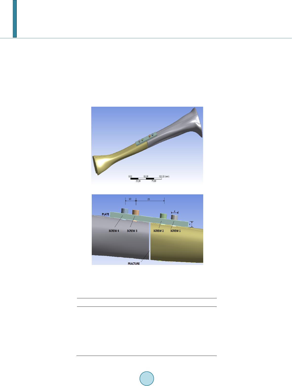
fracture angle is 30˚. It is evident that the Screw 2 is close to the fracture so it is an expected situation. The
minimum von Mises stress is found when the fracture angle is 45˚ on the Screw 4.
4. Conclusion
The purpose of the present study is to evaluate the use of the maximal Von Mises stress calculated by finite
element analysis as a measure for examination of the fracture mechanisms of the tibia bone. The maxima stress
is found on the screw next to the fracture gap. It is also found that the fracture angle 30˚ causes the highest stress
on the screw and the plate.
Acknowledgements
We would like to thank Scientific Researches Supporting Unit of Firat University (FUBAP) for the financial
support.
References
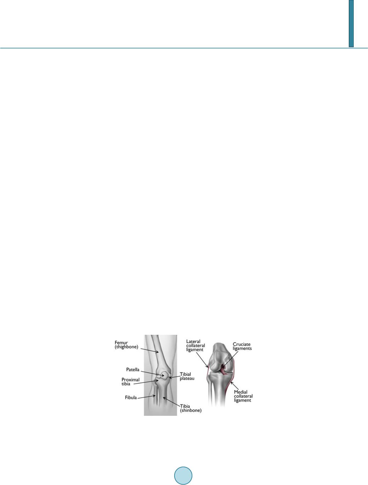
[1] http://orthoinfo.aaos.org/topic.cfm?topic=A00393 (Left picture is reproduced with permission from The Body Alma-
nac. © American Academy of Orthopaedic Surgeons, 2003. Right picture is reproduced with permission from J
Bernstein, ed: Musculoskeletal Medicine. Rosemont, IL, American Academy of Orthopaedic Surgeons, 2003).
[2] Spivak, J.M., Z uckerman, J.D., Kummer, F.J. and Frankel, V.H. (19 91 ) Fatigue Failure of the Sliding Screw in Hip
Fracture Fixation: A Report of Three Cases. Journal of Orthopedic Trauma, 5, 325-331.
http://dx.doi.org/10.1097/00005131-199109000-00012
[3] Kim, H.J., Kim, S.H. and Chang, S.H. (2011) Bio -Mechanical Analysis of a Fractured Tibia with Composite Bone
Plates According to the Diaphyseal Oblique Fracture Angle. Composites: Part B, 42 , 666-674.
http://dx.doi.org/10.1016/j.compositesb.2011.02.009
[4] Kim, S .H., Chang, S.H. and Son, D.S. (2011) Finite Element Analysis of the Effect of Bending Stiffness and Contact
Condition of Composite Bone Plates with Simple Rectangular Cross-S ection on the Bio-Mechanical Behavior of Frac-
tured Long Bones. Composites: Part B, 42, 1731-1738. http://dx.doi.org/10.1016/j.compositesb.2011.03.001
[5] Wong, C., Mikkelsen, P., Hansen, L.B. , Darvann , T. and Gebuhr, P. (2010 ) Finite Element Analysis of Tibial Fractures.
Danish Medical Bulletin, 57, 1-4.
[6] K im, S.H. , Chang, S.H. and Jung, H.J. (2010) The Finite Element Analysis of a Fractured Tibia Applied by Composite
Bone Plates Considering Contact Conditions and Time -Varying Properties of Curing Tissues. Composite Structures, 92,
2109-2118. http://dx.doi.org/10.1016/j.compstruct.2009.09.051
[7] Aizat, R.M., Kadir, M.R.A., Rahman, S. A., Shihabudin, T.M.T.M., Robson, N. and Kamarul, T. (2013) Biomechanical
Comparative Analyses between the Anterolateral and Medial Distal Tibia Locking Plates in Treating Complex Distal
Tibial Fracture: A Finite Element Study. Journal of Medical Imaging and Health Informatics, 3, 532-537.
http://dx.doi.org/10.1166/jmihi.2013.1194
[8] Degirmenci, G. (2005) Investigation of the Effect of Implants Used in Extremity Fractures on Movement Restrictions.
Master in Science Thesis, Natural Science Institute of Uludag University, Turkey.
[9] Yildiz, H. and Erden, S. (2001 ) An Advanced Structural Design for Bone Plate. Proceedings of 18th International So-
ciety of Biomechanics Congress, Zurich, Switzerland, 8-13 July 2001.
[10] http://orthopedics.about.com/od/brokenbones/a/tibia.htm updated on February 2nd, 2014.