Journal of Power and Energy Engineering, 2014, 2, 712-717
Published Online April 2014 in SciRes. http://www.scirp.org/journal/jpee
http://dx.doi.org/10.4236/jpee.2014.24095
How to cite this paper: Thipprasert, W. and Sritakaew, P. (2014) Leakage Currents of Zinc Oxide Surge Arresters in 22 kV
Distribution System Using Thermal Image Camera. Journal of Power and Energy Engineering, 2, 712-717.
http://dx.doi.org/10.4236/jpee.2014.24095
Leakage Currents of Zinc Oxide Surge
Arresters in 22 kV Distribution System
Using Thermal Image Camera
Wichet Thipprasert, Prakasit Sritakaew
Department of Electrical Engineering, Faculty of Engineering, Rajamangala University of Technology Lanna
Chiang Rai, Chiang Rai, Thailand
Email: wichet_thhip@rmutl.ac.th, prakasit.sri@gmail.com
Received December 2013
Abstract
Zinc Oxide (ZnO) surge arresters (SAs) experience thermal runaway when the temperature ex-
ceeds the acceptable limit. This phenomenon is associated with the increase in resistive leakage
current due to degradation. This paper presents the electrical performance of ZnO SAs in 22 kV
distribution systems using thermal image camera under the power frequency AC operating vol-
tages. When ZnO surge arresters are installation takes a long time in distribution system over
more than 5 years. For the experimental study, as ZnO installation takes a long time over 6 years
the leakage current is 63.9 mA, temperature differences were measured over a period of time over
14 degree Celsius. This data will be useful as a guideline for solving problems and reducing power
loss from leakage current. Moreover, it will be useful in predicting lifetime of ZnO SAs.
Keywords
Electrical Performance; Surge Arrester; Thermal Image Camera
1. Introduction
High voltage systems are often subject to transient overvoltages of internal or external origin. The resultant
surges travel along the transmission line and can cause damage to unprotected terminal equipment. Corona
losses and the earth return path can attenuate and distort the surges, but the magnitude of the surge may still ex-
ceed the insulation level of the equipment. SAs provide a limitation of the overvoltage to a chosen protective
level. The superiority of the recently developed ZnO material over the earlier used silicon carbide (SiC) renewed
interest and boosted the use of SA protection.
The excellent voltage-current nonlinearity of ZnO elements ha ve been successfully utilized to eliminate series
gap in ZnO SA, which are replacing conventional series gap arresters with SiC nonlinear resistors. However, in
its initial stage of development, ZnO SA had to be so designed that the normal operating voltage stress applied
to the elements was relatively low to minimize degradation due to the normal operating voltage stress, resulting
in a restricted improvement of protective characteristics. In other words, the resistance values are decreased as
temperature rises. It is also well known that when temperature on the ZnO elements exceeds the limit by ab-
W. Thipprasert, P. Sritakaew
713
sorbing surge energy, the phenomenon of thermal runaway occurs as a result of increased heat generation caused
by subsequent ac voltage application. SA must not only be thermally stable at normal operating stress, but must
also discharge various transient overvoltage energies and return to the former thermally stable condition from
the temporary high temperature state. The latter is termed transient thermal stability. In the following text, tran-
sient thermal stability is abbreviated to thermal stability. When the operating stress becomes higher, the ab-
sorbed energy for transient overvoltages becomes larger because the current created by transient overvoltages is
larger. Therefore, the discharge capability requirement and the transient thermal stability are more severe in the
case of high operating stress [1-3].
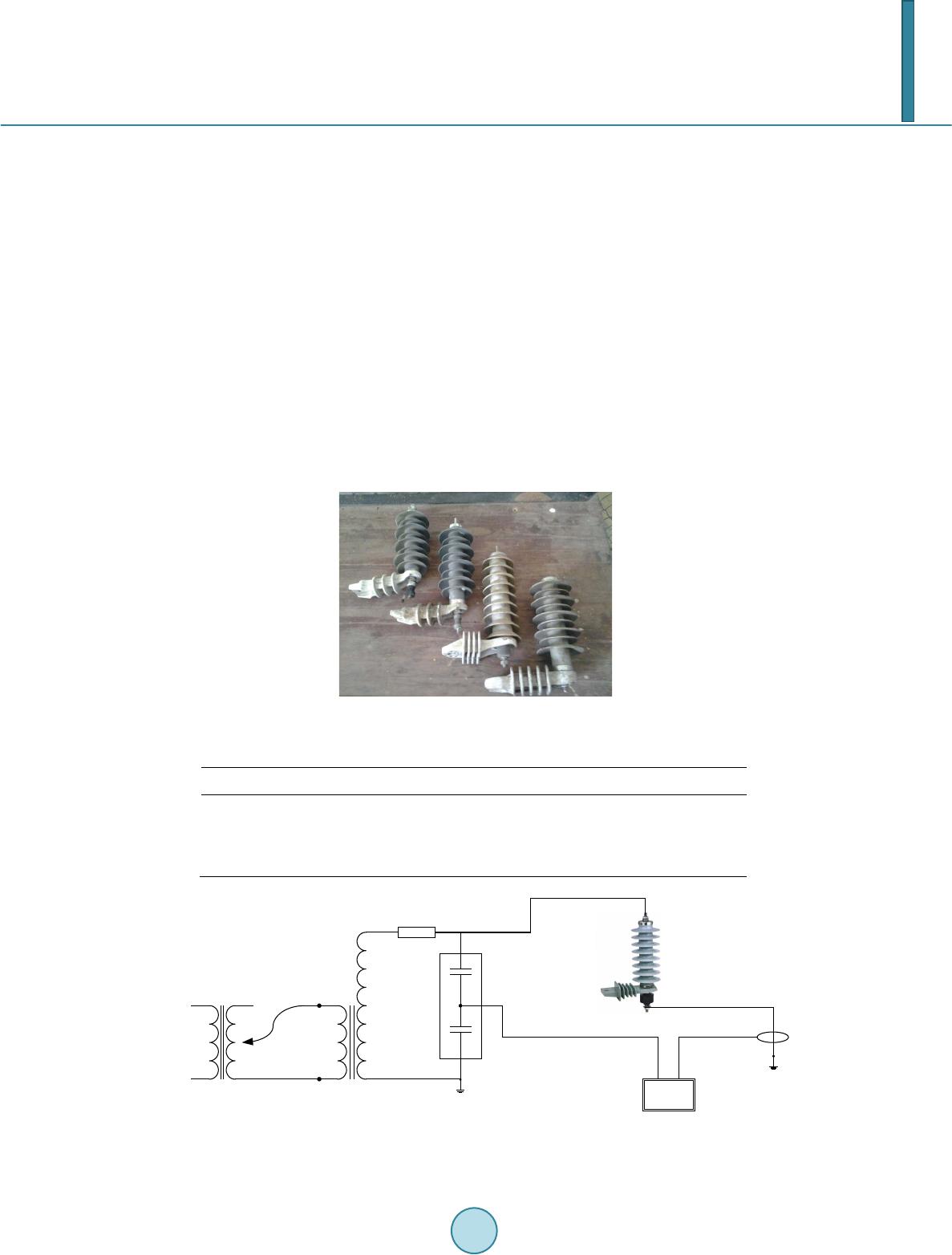
ZnO SAs are fundamental elements of protecting systems of electric devices against overvoltages. They con-
tain varistores, which have ZnO as the main constituent as well as small amounts of other metal oxides. SAs are
exposed to transient effect of overvoltages generated as a result of lightning discharges, switching and damage
states in electric power systems.
This thermal runaway phenomenon can be studied as a problem of balance between heat generation and heat
dissipation. Conventionally, this problem has been discussed simply as static phenomenon on the basis that heat
generation of ZnO elements was uniform along the ZnO columns, while their heat dissipation was equally uni-
form [1,3]. Actual measurements were also conducted on single or several series-connected ZnO elements that
possessed different heat dissipating conditions.
The electrical energy is then converted and stored in the metal oxide valve elements as thermal energy, thus
resulting in a temperature rise above normal operating levels. An increase of valve element temperature can up-
set the thermal balance in the arrester assembly, resulting in a thermal runaway. Since, the thermal capabilities
of gapless metal oxide SAa depend on ambient temperature and solar radiation gain, both factors must be consi-
dered in application studies. Such studies can now be carried out using a relatively simple and yet representative
model of the thermal properties at the arrester valve element and housing [1].
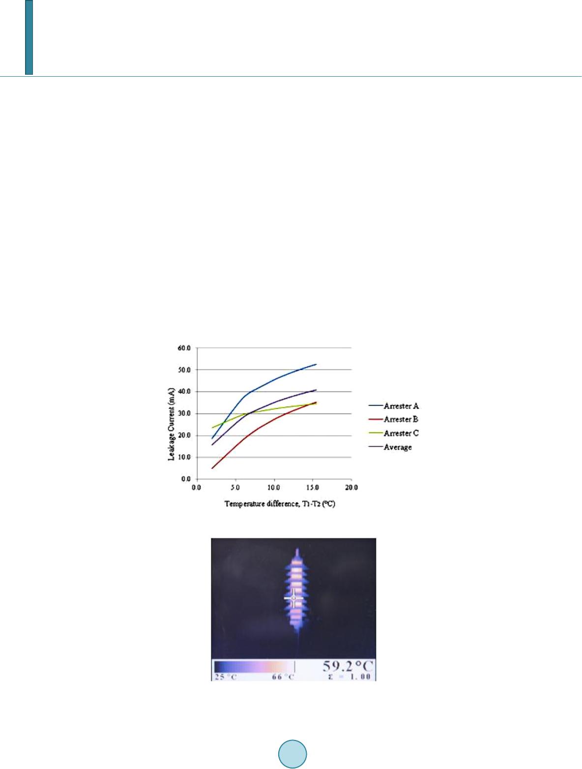
In this research, in order to understand the thermal and electrical properties of a ZnO SAs 50 Hz AC voltage
changes in leakage current were measured. The temperature distribution appearing on the ZnO SA was observed
using a forward looking infrared camera. In particular, the correlation between the thermal and electrical proper-
ties of a ZnO SA was analyzed experimentally. From this analysis, the thermal phenomena resulting from the
heat generation and dissipation of the ZnO SA wer e interpr eted.
2. Thermal Performance of ZnO Surge Arrester [1]
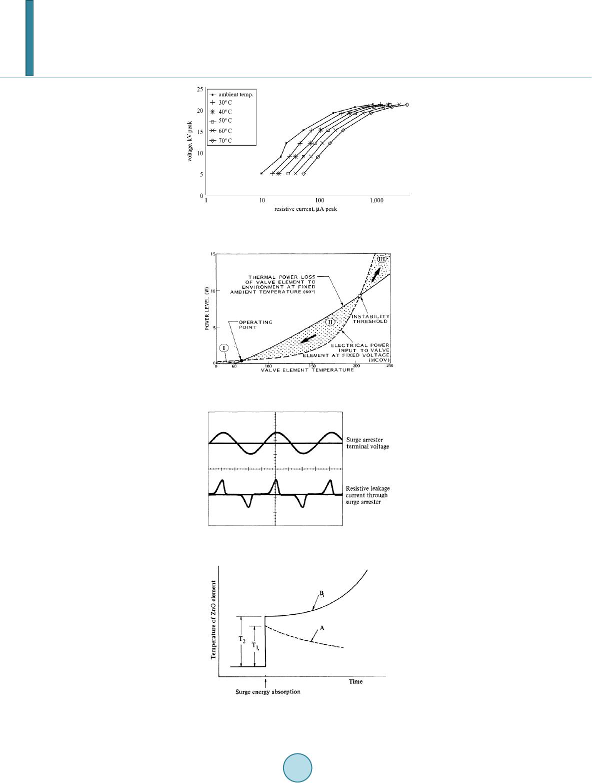
The thermal stability of ZnO SA is affected by ambient temperature and heat dissipation capability, impulse de-
gradation and ageing. To obtain thermal stability, the electrical power dissipation in the element must be ba-
lanced against heat output to the environment. Near the thermal equilibrium, it is possible to express the thermal
dissipation capacity Q of a SA as:
( )
aT
TTCQ −=
(1)
where T is the temperature of ZnO valve elements, Ta is the ambient temperature and CT the thermal dissipation
factor. The heat generation, P, which is voltage and material composition dependent, may be approximated by
( )
/
c
W kT
T Ae=
(2)
where Wc is the activation energy, k = 0.86 × 10 eV/K (Boltzmann constant), T is the temperature of the material
and A depends on the applied voltage level and the physical dimensions of the valve elements. The above curves
are shown schematically in Figures 1 and 2. For an ambient temperature Ta and an applied voltage V, the two
curves intersect at two points X and Y. The lower point X is at a stable operating temperature Tx and is referred
to as the lower limit stability point. The upper point Y is also at a stable operating temperature Ty and is called
the upper limit stability point. At these temperatures, the power input equals the power output.
3. Thermal Runaway Phenomenon of ZnO Surge Arrester [1,3]
When a ZnO SA is connected to a distribution system, resistive leakage current is less than 1 mA flows through
the arrester, as shown in Figure 3. However, when large surge energy of power system is absorbed, the temper-
ature of ZnO elements increases, causing the resistance value to decrease. As a result, the leakage current be-
comes greater and the heat generation increases. Even if the heat generation increases, the temperature rise by
surge energy absorption T1 shown in Figure 4 may be below the certain temperature limit intrinsic to the SA.
W. Thipprasert, P. Sritakaew
714
Figure 1. Temperature dependence of ZnO voltage current
characteri stic.
Figure 2. Evaluation of ZnO surge arrester steady
state stability using the heat loss-input characteristic.
Figure 3. Resistive leakage current flowing through
surge arrester when AC voltage is supplied.
Figure 4. Thermal runaway phenomenons on zinc-
oxide surge arrester.
W. Thipprasert, P. Sritakaew
715
4. Test Specimens, Setups, and Procedures
4.1. Test Specimens
The specimens are ZnO surge arresters in 22 kV distribution systems as shown in Figure 5 consist ZnO SA No
A 21 kV rated voltage installation takes a long time in distribution system over more than 6 - 7 years, No B 21
kV rated voltage installation takes a long time in distribution system over more than 5 year and No B 21 kV
rated voltage installation takes a long time in distribution system over more than 5 - 6 years and Table 1 shows
the parameters of the samples test.
4.2. Test Setup
The test circuit of ZnO SA is provided schematically in Figure 6. The voltage elevation transformer is supplied
by a Variac, thus resulting in a controlled gradual voltage increase. The transformer secondary coil is connected
in series resistance R0 = 2 MΩ and parallel with a capacitive voltage divider comprised of capacitors C1 and C2
respectively. In parallel with the voltage divider is the series connected of the insulator. The voltage across C2 is
measured by a scope meter (190B Scope Meter Series: Fluke) and connected to a computer where it is recorded
and visually displayed with the use of appropriate software. The technical characteristics of the capacitors C1
and C2 were 224 pF, 100 kV/50 Hz and 2 µF, 1000 V/50 Hz, respectively.
Figure 5. Test objects.
Table 1. Parameters of ZnO surge arrester.
No. Material Rated Voltage (kV) installation takes a long time
A Polymer coat 21 6 - 7 years
B Polymer coat 21 5 years
C Polymer coat 21 5 - 6 years
Figure 6. Schematic of testing.
C1
C2
R0
230/400 V.
AC 50Hz
1 2
Scope meter
Current prob
W. Thipprasert, P. Sritakaew
716
4.3. Test Procedures
The research was carried out on three ZnO SAs of 22 kV distribution system of PEA. It is installation in distri-
bution system over more than 5 years with parameter given in the Table 1. The experimental set-up is schemat-
ically shown in Fig ure 6. Referring to the test standard [1-3], the test procedures in the paper were as follows.
After the connected circuit in Figur e 6 completely, ac voltage was applied to the specimens and increased at a
constant rate till the voltage is 18 kV. Then ac voltage supplied to specimens is a long time 3 hours. The thermal
image camera (Fluke Ti32) records the temperature profile and the leakage current, as shown in Figure 8 and
Table 2.
5. Test Results of ZnO Surge Arrester
The results form experiments are shown in Table 2, Figures 7 and 8. From F igure 8 shows the temperature of
the central ZnO element as a function of time during the IEC type test [4,5]. The result experiments arrester No
A maximum temperature of arrester increasing to 42.5 degree Celsius as ambient temperature is 27.1 degree
Celsius, leakage current increase to 63.9 mA. Arrester No B maximum temperature of arrester increasing to 49.1
degree Celsius as ambient temperature is 25.6 degree Celsius, leakage current increase to 46.2 mA.
And arrester No C maximum temperature of arrester increasing to 46.3 degree Celsius as ambient temperature
is 25.2 degree Celsius, leakage current increase to 37.6 mA. However, the temperature of ZnO surge arrester No
C is over than all ZnO surge arrester but leakage current of less than No A and No B because installation takes a
long time in distribution system is over than all ZnO surge arrester. Therefore the temperature of ZnO surge ar-
rester can be used for estimation of leakage current.
Figure 7. Temperature and leakage current curve.
Figure 8. Temperature of arrester with 18 kV
ac voltages applied
W. Thipprasert, P. Sritakaew
717
Table 2. The leakage current and temperature of arresters; 18 kV ac voltage applied.
Arrest er
No. Leakage
current (mA) Maximum Temperature
of arrester (T1, ˚C) Ambient Temperature
(T2, ˚C) Temperature Difference
(T1 - T2, ˚C)
A
31.2 3 6.2 3 0.4 5 .8
42.8 4 1.3 2 8.9 1 2.4
63.9 4 2.5 2 7.1 1 5.4
B
33.9 4 0.2 2 6.2 14
36.8 4 4.5 2 5.9 1 8.6
46.2 4 9.1 2 5.6 2 3.5
C
30.5 3 2.8 2 5.2 7 .6
34.1 42 25. 1 16. 9
37.6 4 6.3 2 5.2 2 1.1
6. Conclusions
The thermal and electrical performances of ZnO SA were experimentally investigated. The results can be sum-
marized as follows.
The total leakage current flowing through the Zno SA under power frequency is the sum of capacitive and re-
sistive currents. The temperature profiles of Zno SAs are observed by thermal imager and the leakage current.
Initially, the nominal voltage and leakage current is 63.9 mA. The temperature of Zno SAs is close to the am-
bient temperature. Increase in the leakage current results in increase of the temperature profile.
Results from the experiment are used for ZnO surge arresters are installation takes a long time in distribution
system over more than 5 years. These results can be guideline for solving problems and reducing power loss due
to leakage current. Moreover, it will be useful to predict lifetime of ZnO SAs installed in distribution system.
References
[1] Hadd ad, A. and Warne, D. (2004) ZnO Surge Arresters. Advance in High Voltage Engineering, lET Power & Energy
Series, 40, 19 1-215.
[2] Lee , S.B., Lee, S.L. and Lee, B.K. (2009) Analysis of Thermal and Electrical Properties of ZnO Arrester Block. Cur-
rent Applied Physics, 10, 176-18 0.
[3] Nishi waki, S., Kimura, H., Satoh, T., Mizoguchi, H. and Yanabu, S. (1984) Study of Thermal Runaway/Equivalent
Prorated Model of a ZnO Surge Arrester. IEEE Transaction on Power Apparatus and Systems, PAS-103, 413 -421 .
http://dx.doi.org/10.1109/TPAS.1984.318260
[4] (1986) IEC Publ.815, First Edition. Guide for the Selection of Insulators in Respect of Polluted Conditions. In t er na-
tional Electrotechnical Committee.
[5] (2004) International Standard of Surge Arrester IEC60099-4 Edition 2.1:2004 Consolidated With Amendment 1: 2006
Section 6.9 Operating Duty, Section 10 Test Requirement on Polymer-Housed Arresters and Annex B Test to Verify
Thermal Equivalency Between Complete Arrester and Arrester Section, IEC60099-4.