Journal of Power and Energy Engineering, 2014, 2, 193-197
Published Online April 2014 in SciRes. http://www.scirp.org/journal/jpee
http://dx.doi.org/10.4236/jpee.2014.24027
How to cite this paper: Dosaev, M.Z., Klimina, L.A., Selyutskiy, Y.D., Tsai, M.-C. and Yang, H.-T. (2014) Behavior of HAWT
with Differential Planetary Gearbox. Journal of Power and Energy Engineering, 2, 193-197.
http://dx.doi.org/10.4236/jpee.2014.24027
Behavior of HAWT with Differential
Planetary Gearbox
Marat Z. Dosaev1, Liubov A. Klimina1, Yury D. Selyuts kiy1, Mi-Ching Tsai2, Hong-Tzer Yang3
1Institute of Mechanics, Lomonosov Moscow State Universit y, Moscow, Russia
2Department of Mechanical Engineering, National Cheng Kung University, Tainan City, Taiwan
3Department of Electrical Engineering, National Cheng Kung University, Tainan City, Taiwan
Email: dosayev@imec.msu.ru
Received December 2013
Abstract
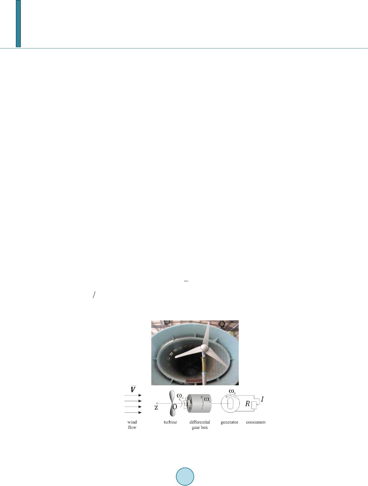
A dynamic model for simulatin g beh avior of a horizontal axis wi n d turbi n e (HAWT) with differen-
tial planetary gearbox is developed. The aerodynamic load applied to the wind t urbi ne connected
with the carrier is described using the quasi-steady approach. The control torque is assumed to be
applied to the external ring of th e gearbox. Steady regimes of the device a re analy zed, and thei r
stability is studied. For the case of constant control torque, powe r costs are estimated required for
preserving constant angular speed of the generator.
Keywords
HAWT; Wind Engineering; Differential Planetary Gearbox; Stabi lity
1. Introduction
Wind power sys t ems in th e world power industry gain more and more importance for many reasons, ranging
from ecological to political. A wide scope of engineering and scientific research of w in d turbine electrodynam-
ics is reflected in numerous papers and patents ([1]).
Practical tasks in wind turbine applications o ften impose requirements on an angular speed of a rotor of a ge-
nerator. In particular, a very common requirement is to maintain angular speed of the rotor within a certain
range near a specific value. Fo r this purpose, ove rdr iv e transmission gear s are used, the most wide-sp read of
which is a planet gear. One of more advanced type s of such devices is a differential planet gear (DPG) that al-
lows controlling the output angular speed. This mechanism consists of two coaxial gearwheels with different
diameters (an external r in g and a so-called sun), several small gearwheels (so-called planets), and a carrier to
which centers of planets are connected.
Planet gears are widely used in engineering (e.g., in automotive industry). In the same time, introduction of
this mechanism into wind turbine construction can be considered as a rather new approach revealing a variety of
innovative opportunities. In particular, DPG can be used for control of a wind turbine dynamics under changing
external conditions of operation (for instance, variable wind speed or resistance of the external circuit).
In this paper, the wind power system w ith D PG is studied, and possibilities for its control are analyzed. The
mechanical system under consideration consists of a ho r iz on tal axis w ind turbine (HAWT), a DPG and a gene-
M. Z. Dosaev et al.
194
rator (Figure 1). Ax is of the turbine is connected to the carrier of the gear box. Rotor of the generator is con-
nected to th e sun gear , the generator being connected to the electrical circuit w ith changeable external resistance.
Rotation of the external ring of the differential planetary gear box is supposed to be controlled via external
control torque applied to this ring. In contrast to man y othe r inves tig ations of DPG application s fo r win d pow er
systems (e.g., [1-5]) this paper deals with dynamics of the so-called small -scale stand-alone wind power system
(not connected to the grid).
Such systems can be used for remote households and infrastructural objects, for camping trips and expeditions.
Distinguishing feature of dynamics of an autonomous power system is that the generator of such system
represents the only electrical power source in its circuit. In this work it is taken into account that electromechan-
ical torque acting on the generator rotor depends on external resistance in the circuit of th e generator as well as
on electromechanical properties of the generator.
2. Problem Statement and Motion Equations
Ass ume that the HAWT is located in a w ind f low w ith the speed V. All elements of DPG are rigid bodies, and
there is no slipping between the m. Axis of the turbine is rigidly connected to the carrier of DPG. Let
c
ω
be the
angular speed of the turbine. The angular speed of the generator rotor is equal to the angular speed
s
ω
of the sun
gear. Angular speed of th e external ring is
r
ω
.
External torques acting on the system are as follows: an aerodynamic torque
c
T
acting on the turbine (and
thereby to the carrier), electromechanical torque
s
T
acting on the generator rotor (and, hence, onto the sun gear)
due to consumers present in the external circuit of the generator, and the control torque
r
T
applied he external
ring of the DPG.
The following constant parameters of the model are introduced:
,,,
cspr
rrrr
are radiuses of the carrier, sun
gear, planet gear and external ring respectively, such that
,
csprcp
rrrrrr=+=+
Supposing that there is no slipping in the DPG, we obtain th e follow ing kinematical relation s:
,2
pprrcc ssccrr
r rrrrr
ω ωωωωω
=−=−
The aerodynami c torque is assumed to be determined with the following formula:
. (1)
where
c
bV
λω
=
is TSR, b is turbine radius, S is the characteristic area of the turbin e.
The function
()f
λ
(non-dimensional aerodynamic torque) was identified for a particular wind turbine bas-
ing on experiments performed in the Institute of Mechanics:
Figure 1. Experimental setup in the wind tunnel of the LMSU
Institute of Mechanics and a scheme of the system.
M. Z. Dosaev et al.
195
54 32
( )0.000160.00470.0480.190.160.11f
λλλ λλλ
=−+−+ −+
Results are shown in Fig ure 2, where dots denote experimental data and the solid line means approximation
curve. Evidently, agreement is good enough.
External load upon th e turbine and generator is modeled accordingly to the [6,7]. So the expression for elec-
tromechanical torque acting on the rotor of the generator is the following:
ss
Tc
ω
=
Here c is the coefficient of electromechanical interaction.
In what follows we assume that the inductance of the generator is small enough, so that the current I in the
external circuit is given by the following formula:
( )
1
s
I cRr
ω
= +
,
where R is resistance of the external circuit, and r is internal resistance of the generator.
Motion equations of the considered system can be written in the following non-dimensional form:
( )
1 23
λAfAu A
λµ
= −−
. (2)
( )
1 23
λBfBu B
µµ
= +−
. (3)
Here
τ/Vt b=
is non-dimensional time (dot denotes derivative with respect to τ),
0
μω
s
µ
=
is normalized
angular speed of the generator,
r
u UT
= −
is non-dimensional control (
r
T
is control torque applied to the ring),
and A1-3, B1-3, U, µ0 are positive constants.
3. Steady Regimes in Case of Constant Control
Ass ume n ow th at th e control torque is constant:
0
uu
. Then , tak ing in t o account (1), on e can readily show that
the dynamic system (2)-(3) can have different number of fixed points for different values of u0: for small enough
and large enough values there exists only one steady regime, while in the intermediate range there are three such
regimes.
Stability condition of steady regimes looks as follows:
( )
λ0
f<
. (4)
Note that if there exists only one steady solution, it is asymptotically stable. If ther e exist three such solutions,
then those with the highest and the lowest angular speeds are asymptotically stable, and the one with the “me-
dium” angular speed is unstable ( th is fixed point is saddle).
4. Output Pow er Estimation
The common task for a DPG mechanism is to maintain a preliminary chosen value of the angular speed of a sun
gear even in changeable external conditions. This value depends on technical requirements of a particular gene-
rator.
Figure 2. The identified function of norma-
lized aerodynamic torque.
M. Z. Dosaev et al.
196
For the case of a wind power system, such operation conditions as win d speed and external load change fre-
quently. The control torque is applied to achieve a needed value of the angular speed of the sun. Power for sup-
plying of the control mechanism can be taken from some storage—additional source of energy that is used to
overcome short periods of unfriendly exploitatio n cond itions w ithou t brakes in the system performance.
This storage can be replenished from the power produced by the wind power generator during advantage pe-
riods of exploitation conditions: i.e. while the wind is strong enough or while the number of primary consumers
is small.
It is necessary to give some esti mation of power costs required by the control system, in order to calculate
what should be the profit of wind power system exp lo itation in the region with a given range of wind speed and
for supposed values of external load from consumers that ma y change.
Ass ume th at angular speed of the sun on an op eration mode should be equal to
*
s
ω
.
From equations of steady regimes we can obtain the requi red value of the control torque Tr and estimate pow-
er costs for the control: mechanical power necessary for the control equals to
cost rr
PT
ω
=
.
If the value
cost
P
is less than zero, it means that control torque is used not to accelerate the external ring gear
but to decelerate it, hence, in such case no power is spent for the control and even additional power can be
trapped from the external ring rotation.
The output electrical power is represented by the value
2
out
P IR=
, where I is the current in the external cir-
cuit, and R is the external resistance.
Hence, in order to estimate the profit power, the following expression can be used:
2
profitr r
PIR T
ω
= −
.
On Figures 3-6, examples of power estimation for the system with given parameters are presented for two il-
lustrative cases. In the first case (F ig ures 3 and 4) it is assumed that external load doesn’t change (100 Ohm)
while wind speed V can take any value from 0 to 15 mps. In the second case (Figures 5 and 6) calculations are
performed for fixed wind speed (12 mps), but fo r different values of the external load.
For both cases the hysteretic behavior is obtained: the final profit power in a certain range depends on the di-
rection of changing of external conditions (both wind speed and external resistance).
Figure 3. Estimation of the output power
and costs for control for R = 100 Ohm.
Figure 4. Estimation of the profit power for
R = 100 Ohm.
M. Z. Dosaev et al.
197
Figure 5. Estimation of the output power
and costs for control for V = 12 mps.
Figure 6. Estimation of the profit power for
V = 12 mps.
5. Conclusion
The behavior of the wind power system inclu d ing differential planet gear was analyzed. Conditions of stability
of steady solutions of the corresponding dynamic system were obtained. Steady operation modes corresponding
to stable steady solution s were studied depending on changing external conditions. Power costs for th e control
were estimated for the system with a certain set of model parameters.
Acknowledgements
This work was partially supported by the Russian Foundation for Basic Research, projects NN 14-08-01130,
11-08-92005, and 12-01-00364 and by the Taiwan National Science Council.
References
[1] Chen, Z., Guerrero, M. and Blaabjerg, F. (2009) A Review of the State of the Art of Powe r Electronics for Wind Tur-
bines. IEEE Transactions on Power Electronics, 24, 1859-1875. http://dx.doi.org/10.1109/TPEL.2009.2017082
[2] Müller, H., Pöller, M., Basteck, A., Tilscher, M. and Pfister, J. (2006) Grid Compatibility of Variable Speed Wind
Turbines with Directly Coupled Synchronous Generator and Hydro-Dy na mica lly Controlled Gearbox. 6th Intl Work-
shop on Large-Scale Integration of Wind Power and Transmissi on Networks for Offshore Wind Farms, Del ft, 26-28
October 2006, 307-315.
[3] Polinder, H., van der Pijl, A.F.F., de Vilder, G.-J. and Tavner, P.J. (2006) Comparison of Direct-Drive and Geared
Generator Concepts for Wind Turbines. IEE E Transactions on Energy Conversion, 21, 725-733.
http://dx.doi.org/10.1109/TEC.2006.875476
[4] Rossi, C., Corbelli, P. and Grandi , G. (2009) W-CVT Continuously Variable Transmission for Wind Energy Conver-
sion Sy st e m . http://www.die.ing.unibo.it/pers/grandi/papers/PEMWA2009.pdf
[5] Tsai, M.-C. and Huang, C.-C. (2012) Development of a Variable-Inertia Device with a Magnetic Planetary Gear-Box.
IEEE-ASME Transactions on Mechatronics, 16, 1120-1128. http://dx.doi.org/10.1109/TMECH.2010.2077679
[6] Dosaev, M.Z., Kobrin, A.I., Lokshin, B.Ya., Samsonov, V.A. and Sely ut skiy, Yu.D. (2007) Constructive Theory of
Small-Scale Wind Power Generators. Part I-II. MSU Publishing, Moscow.
[7] Dosaev, M.Z., Samsonov, V.A. and Seliutski, Yu.D. (2007) On the Dynamics of a Smal l-Scale wind Power Generator.
Doklady Physics, 52, 50-53. http://dx.doi.org/10.1134/S1028335807090091