Journal of Power and Energy Engineering, 2014, 2, 7-12
Published Online April 2014 in SciRes. http://www.scirp.org/journal/jpee
http://dx.doi.org/10.4236/jpee.2014.24002
How to cite this paper: Wang, B.C., Han, G.Y. and Zhu, L. (2014) Research on Technology of Electromagnetic Protection for
the Generator Control System. Journal of Power and Energy Engineering, 2, 7-12.
http://dx.doi.org/10.4236/jpee.2014.24002
Research on Technology of Electromagnetic
Protection for the Generator Control System
Baocheng Wang, Guyong Han, Lin Zhu
Xuzhou Air Force College, Xuzhou, China
Email: xzkjxywangbaocheng@163.com
Received December 2013
Abstract
Generator control system decides whether the generator can work as usual or not, as well as its
stability of performance. Both types of generators control system composed of the transistor and
DSP are sensitive to outward electromagnetic interference, directly related to the generator per-
formance. In this text, we first analyze the electromagnetic interference threat generator control
system of transistor type may face, then design a electromagnetic protection plan for the intake,
the panel and the sense organ. This work is of great significance in improving its electromagnetic
protection ability and stability of performance.
Keywords
Generator Control System; Electromagnetic Interference Damage Analysis; Electromagnetic
Protection Design
1. Electromagnetic Interference Threat Analysis of Generator Control System
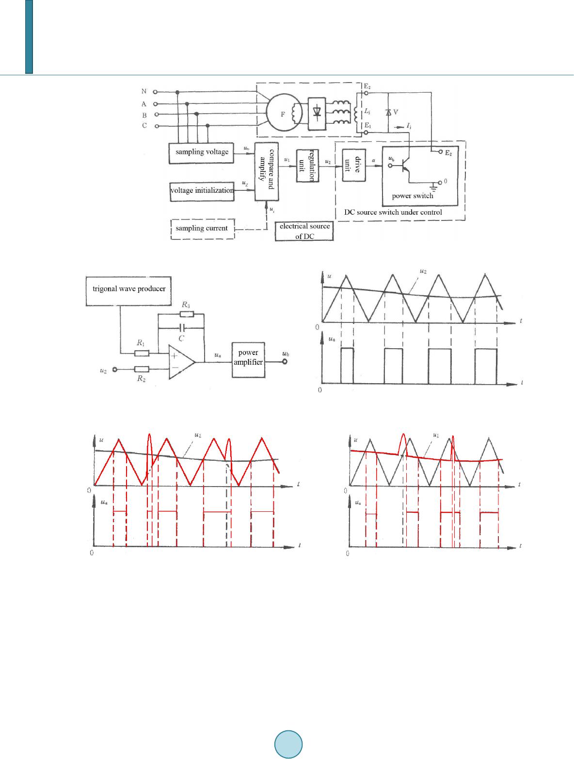
Electromagnetic interference mainly gives an effect on the booster in control system. The principle and structure
of transistor type are shown by Figure 1.
The drive unit composed of triangle wave producer, voltage comparer and driver amplifier circuit, output
square wave ub, as drive power switch. Triangle wave producer output triangle waves of certain value and fre-
quency, without in-phase problem. Voltage comparer completes the square wave output ua after comparing tri-
gonal wave with control voltage u2 and amplifying the signal. The output is low voltage when the value of tri-
gonal wave is less than u2, while high voltage on the contrary, just as Figure 2 shows. Triangle wave producer
and voltage comparer can be gained by operational amplifier circuit. After processed through power amplifying
and opposite phase ua are translated as the drive signal ub. The drive unit is also a proportional tache with the
input u2 and the output ua.
With coupling interference signals to PID regulate circuit, the scope of trigonal wave changes or control vol-
tage becomes uncertain which makes the value of ton/T (expressed as) out of gear, as is shown by Figure 3.
Thus, the value of actual excitation current will be restricted by interference signals. What’s more, uncertain
value of interference signals result in excitation current regulate chaos, which cause excitation current out of
control, then boosters abnormal voltage regulate, after that generators uncertain voltage output, finally power
supply vehicle failure in airplanes start-up or offering electrifying check.