Paper Menu >>
Journal Menu >>
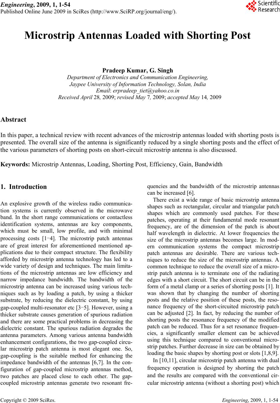 Engineering, 2009, 1, 1-54 Published Online June 2009 in SciRes (http://www.SciRP.o rg/journal/eng/). Copyright © 2009 SciRes. Engineering, 2009, 1, 1-54 Microstrip Antennas Loaded with Shorting Post Pradeep Kumar, G. Singh Department of El ectroni cs a n d C ommu nication Engineeri n g, Jaypee University of Information Technology, Solan, India Email: erpradeep_tiet@yahoo.co.in Received April 28, 2009; revised May 7, 2009; accepted May 14, 2009 Abstract In this paper, a technical review with recent advances of the microstrip antennas loaded with shorting posts is presented. The overall size of the antenna is significantly reduced by a single shorting posts and the effect of the various parameters of shorting posts on short-circuit microstrip antenna is also discussed. Keywords: Microstrip Antennas, Loading, Shorting Post, Efficiency, Gain, Bandwidth 1. Introduction An explosive growth of the wireless radio communica- tion systems is currently observed in the microwave band. In the short range communications or contactless identification systems, antennas are key components, which must be small, low profile, and with minimal processing costs [1-4]. The microstrip patch antennas are of great interest for aforementioned mentioned ap- plications due to their compact structure. The flexibility afforded by microstrip antenna technology has led to a wide variety of design and techniques. The main limita- tions of the microstrip antennas are low efficiency and narrow impedance bandwidth. The bandwidth of the microstrip antenna can be increased using various tech- niques such as by loading a patch, by using a thicker substrate, by reducing the dielectric constant, by using gap-coup led multi-r esonato r etc [3-5]. However, using a thicker substrate causes generation of spurious radiation and there are some practical problems in decreasing the dielectric constant. The spurious radiation degrades the antenna parameters. Among various antenna bandwidth enhancement configurations, the two gap-coupled circu- lar microstrip patch antenna is most elegant one. So, gap-coupling is the suitable method for enhancing the impedance bandwidth of the antennas [6,7]. In the con- figuration of gap-coupled microstrip antennas method, two patches are placed close to each other. The gap- coupled microstrip antennas generate two resonant fre- quencies and the bandwidth of the microstrip antennas can be increased [6]. There exist a wide range of basic microstrip antenna shapes such as rectangular, circular and triangular patch shapes which are commonly used patches. For these patches, operating at their fundamental mode resonant frequency, are of the dimension of the patch is about half wavelength in dielectric. At lower frequencies the size of the microstrip antennas becomes large. In mod- ern communication systems the compact microstrip patch antennas are desirable. There are various tech- niques to reduce the size of the microstrip antennas. A common technique to reduce the overall size of a micro- strip patch antenna is to terminate one of the radiating edges with a short circuit. The short circuit can be in the form of a metal clamp or a series of shorting posts [1 ]. It was shown that by changing the number of shorting posts and the relative position of these posts, the reso- nance frequency of the short-circuited microstrip patch can be adjusted [2]. In fact, by reducing the number of shorting posts the resonance frequency of the modified patch can be reduced. Thus for a set resonance frequen- cies, a significantly smaller element can be achieved using this technique compared to conventional micro- strip patches. Further decrease in size can be obtained by loading the basic shapes by shorting post or slots [1,8,9]. In [10,11], circular microstrip patch antenna with dual frequency operation is designed by shorting the patch and the results are compared with the conventional cir- cular microstrip antenna (without a shor ting post) which 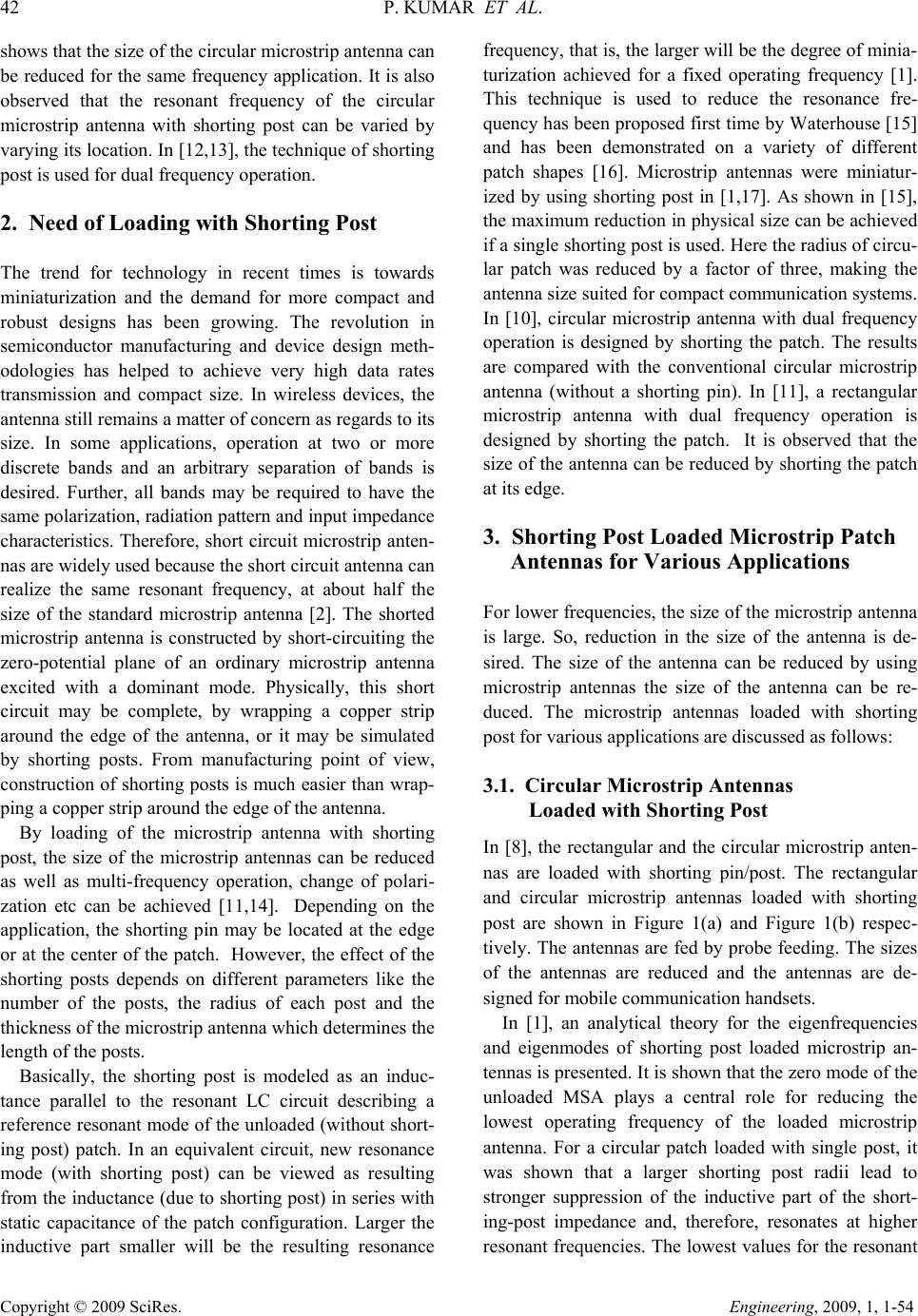 42 P. KUM A R ET AL. Copyright © 2009 SciRes. Engineering, 2009, 1, 1-54 shows that the size of the circular microstrip antenna can be reduced for the same frequency application. It is also observed that the resonant frequency of the circular microstrip antenna with shorting post can be varied by varying its location. In [1 2,13], the technique of shor ting post is used for dual frequency operation. 2. Need of Loading with Shorting Post The trend for technology in recent times is towards miniaturization and the demand for more compact and robust designs has been growing. The revolution in semiconductor manufacturing and device design meth- odologies has helped to achieve very high data rates transmission and compact size. In wireless devices, the antenna still remains a matter of concern as regards to its size. In some applications, operation at two or more discrete bands and an arbitrary separation of bands is desired. Further, all bands may be required to have the same polarization, radiation pattern and input impedance characteristics. Therefore, short circuit microstrip anten- nas are widely used because the short circuit antenna can realize the same resonant frequency, at about half the size of the standard microstrip antenna [2]. The shorted microstrip antenna is constructed by short-circuiting the zero-potential plane of an ordinary microstrip antenna excited with a dominant mode. Physically, this short circuit may be complete, by wrapping a copper strip around the edge of the antenna, or it may be simulated by shorting posts. From manufacturing point of view, construction of shorting posts is much easier than wrap- ping a copper strip around the edge of the antenna. By loading of the microstrip antenna with shorting post, the size of the microstrip antennas can be reduced as well as multi-frequency operation, change of polari- zation etc can be achieved [11,14]. Depending on the application, the shorting pin may be located at the edge or at the center of the patch. However, the effect of the shorting posts depends on different parameters like the number of the posts, the radius of each post and the thickness of the microstrip antenna which determines the length of the posts. Basically, the shorting post is modeled as an induc- tance parallel to the resonant LC circuit describing a reference resonant mode of the unloaded (without short- ing post) patch. In an equivalent circuit, new resonance mode (with shorting post) can be viewed as resulting from the inductance (due to shorting post) in series with static capacitance of the patch configuration. Larger the inductive part smaller will be the resulting resonance frequency, that is, the larger will be the degree of minia- turization achieved for a fixed operating frequency [1]. This technique is used to reduce the resonance fre- quency has been proposed first time by Waterhouse [15] and has been demonstrated on a variety of different patch shapes [16]. Microstrip antennas were miniatur- ized by using shorting post in [1,17]. As shown in [15], the maximum reduction in physical size can be achieved if a single shorting post is used. Here the radius of circu- lar patch was reduced by a factor of three, making the antenna size suited for compact communication systems. In [10], circular microstrip antenna with dual frequency operation is designed by shorting the patch. The results are compared with the conventional circular microstrip antenna (without a shorting pin). In [11], a rectangular microstrip antenna with dual frequency operation is designed by shorting the patch. It is observed that the size of the antenna can be reduced by shorting the patch at its edge. 3. Shorting Post Loaded Microstrip Patch Antennas for Various Applications For lower frequencies, the size of the microstrip antenna is large. So, reduction in the size of the antenna is de- sired. The size of the antenna can be reduced by using microstrip antennas the size of the antenna can be re- duced. The microstrip antennas loaded with shorting post for various applications are discussed as follows: 3.1. Circular Microstrip Antennas Loaded with Shorting Post In [8], the rectangular and the circular microstrip anten- nas are loaded with shorting pin/post. The rectangular and circular microstrip antennas loaded with shorting post are shown in Figure 1(a) and Figure 1(b) respec- tively. The antennas are fed by probe feeding. The sizes of the antennas are reduced and the antennas are de- signed for mobile communication handsets. In [1], an analytical theory for the eigenfrequencies and eigenmodes of shorting post loaded microstrip an- tennas is presented. It is shown that the zero mode of the unloaded MSA plays a central role for reducing the lowest operating frequency of the loaded microstrip antenna. For a circular patch loaded with single post, it was shown that a larger shorting post radii lead to stronger suppression of the inductive part of the short- ing-post impedance and, therefore, resonates at higher resonant frequencies. The lowest values for the resonant 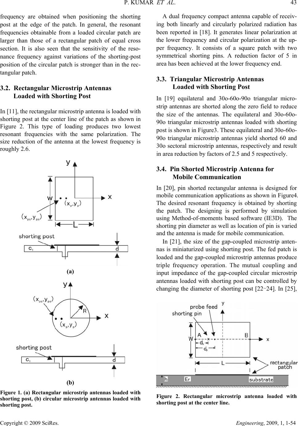 P. KUMAR ET AL. 43 Copyright © 2009 SciRes. Engineering, 2009, 1, 1-54 frequency are obtained when positioning the shorting post at the edge of the patch. In general, the resonant frequencies obtainable from a loaded circular patch are larger than those of a rectangular patch of equal cross section. It is also seen that the sensitivity of the reso- nance frequency against variations of the shorting-post position of the circular patch is stronger than in the rec- tangular patch. 3.2. Rectangular Microstrip Antennas Loaded with Shorting Post In [11], the rectangular microstrip antenna is lo aded with shorting post at the center line of the patch as shown in Figure 2. This type of loading produces two lowest resonant frequencies with the same polarization. The size reduction of the antenna at the lowest frequency is roughly 2. 6. (a) (b) Figure 1. (a) Rectangular microstrip antennas loaded with shorting post, (b) circular microstrip antennas loaded with shorting post. A dual frequency compact antenna capable of receiv- ing both linearly and circularly polarized radiation has been reported in [18]. It generates linear polarization at the lower frequency and circular polarization at the up- per frequency. It consists of a square patch with two symmetrical shorting pins. A reduction factor of 5 in area has been achieved at the lower frequency end. 3.3. Triangular Microstrip Antennas Loaded with Shorting Post In [19] equilateral and 30o-60o-90o triangular micro- strip antennas are shorted along the zero field to reduce the size of the antennas. The equilateral and 30o-60o- 90o triangular microstrip antennas loaded with shorting post is shown in Figure3. These equilateral an d 30o-60o- 90o triangular microstrip antennas yield shorted 60 and 30o sectoral microstrip antennas, respectively and result in area reduction by factors of 2.5 and 5 respectively. 3.4. Pin Shorted Microstrip Antenna for Mobile Communication In [20], pin shorted rectangular antenna is designed for mobile communication applications as shown in Figure4. The desired resonant frequency is obtained by shorting the patch. The designing is performed by simulation using Method-of-moments based software (IE3D). The shorting pin diameter as well as location of pin is varied and the antenna is made for mobile communicatio n. In [21], the size of the gap-coupled microstrip anten- nas is miniaturized using shorting post. The fed patch is loaded and the gap-coupled microstrip antennas produce triple frequency operation. The mutual coupling and input impedance of the gap-coupled circular microstrip antennas loaded with shorting post can be controlled by changing the diameter of shorting post [22-24]. In [25], Figure 2. Rectangular microstrip antenna loaded with shorting post at the center line. 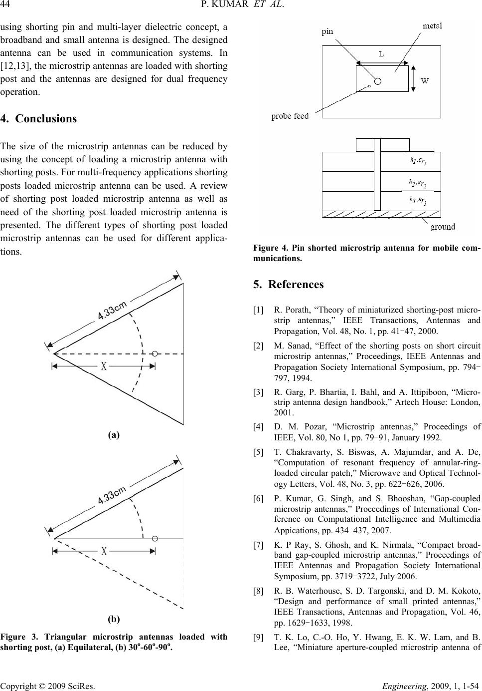 44 P. KUM A R ET AL. Copyright © 2009 SciRes. Engineering, 2009, 1, 1-54 using shorting pin and multi-layer dielectric concept, a broadband and small antenna is designed. The designed antenna can be used in communication systems. In [12,13], the microstrip ante nnas are loaded with shorting post and the antennas are designed for dual frequency operation. 4. Conclusions The size of the microstrip antennas can be reduced by using the concept of loading a microstrip antenna with shorting posts. For multi-frequency applications shorting posts loaded microstrip antenna can be used. A review of shorting post loaded microstrip antenna as well as need of the shorting post loaded microstrip antenna is presented. The different types of shorting post loaded microstrip antennas can be used for different applica- tions. (a) (b) Figure 3. Triangular microstrip antennas loaded with shorting post, (a) Equilateral, (b) 30o-60o-90o. Figure 4. Pin shorted microstrip antenna for mobile com- munications. 5. References [1] R. Porath, “Theory of miniaturized shorting-post micro- strip antennas,” IEEE Transactions, Antennas and Propagation, Vol. 48, No. 1, pp. 41-47, 2000. [2] M. Sanad, “Effect of the shorting posts on short circuit microstrip antennas,” Proceedings, IEEE Antennas and Propagation Society International Symposium, pp. 794- 797, 1994. [3] R. Garg, P. Bhartia, I. Bahl, and A. Ittipiboon, “Micro- strip antenna design handbook,” Artech House: London, 2001. [4] D. M. Pozar, “Microstrip antennas,” Proceedings of IEEE, Vol. 80, No 1, pp. 79-91, January 1992. [5] T. Chakravarty, S. Biswas, A. Majumdar, and A. De, “Computation of resonant frequency of annular-ring- loaded circular patch,” Microwave and Optical Technol- ogy Letters, Vol. 48, No. 3, pp. 622-626, 2006. [6] P. Kumar, G. Singh, and S. Bhooshan, “Gap-coupled microstrip antennas,” Proceedings of International Con- ference on Computational Intelligence and Multimedia Appications, pp. 434-437, 2007. [7] K. P Ray, S. Ghosh, and K. Nirmala, “Compact broad- band gap-coupled microstrip antennas,” Proceedings of IEEE Antennas and Propagation Society International Symposium, pp. 3719-3722, July 2006. [8] R. B. Waterhouse, S. D. Targonski, and D. M. Kokoto, “Design and performance of small printed antennas,” IEEE Transactions, Antennas and Propagation, Vol. 46, pp. 1629-1633 , 1 9 9 8 . [9] T. K. Lo, C.-O. Ho, Y. Hwang, E. K. W. Lam, and B. Lee, “Miniature aperture-coupled microstrip antenna of  P. KUMAR ET AL. 45 Copyright © 2009 SciRes. Engineering, 2009, 1, 1-54 very high permittivity,” Electronics Letters, Vol. 33, pp. 9-10, 1997. [10] C. L. Tang, H. T. Chen, and K. L. Wong, “Small circular microstrip antenna with dual frequency operation,” Elec- tronics Letters, Vol. 33, No. 73, pp. 1112-1113, 1 9 9 7 . [11] K. L. Wong and W. S. Chen, “Compact microstrip an- tenna with dual-frequency operation,” Electronics Letters, Vol. 33, No. 8, pp. 646-647, 1997. [12] T. Chakravarty and A. De, “Investigation of modes tunable circular patch radiator with arbitrarily located shorting posts,” IETE Technical Review, Vol. 16, No.1, pp. 109-111, 1999. [13] T. Chakravarty and A. De, “Design of tunable modes and dual-band circular patch antenna using shorting posts,” IEE Proceedings on Microwave, Antennas and Propaga- tion, Vol. 146, No. 3, pp. 224-228, 1999. [14] A. Vallecchi, G. B. Gentili, and M. Calamia, “Dual-band dual polarization microstrip antenna,” Proceedings, IEEE International Symposium, pp. 134-137, 2003. [15] R. Waterhouse, “Small microstrip patch antenna,” Elec- tronics Letters, Vol. 31, pp. 604-605, 1995. [16] S. Dey and R. Mitra, “Compact microstrip patch anten- nas,” Microwave and Optical Technology Letters, Vol. 13, pp. 12-14, 1996. [17] H. K. Kan and R. Waterhouse, “Size reduction technique for shorted patches,” Electronics Letters, Vol. 35, pp. 948-949, 1999. [18] E. Lee, P. S. Hall, and P. Gardner, “Compact dual-band dual-polarization microstrip patch antennas,” Electronics Letters, Vol. 35, pp. 1034-10 3 6, 1999. [19] S. K. Satpathy, G. Kumar, and K. P. Ray, “Compact shorted variations of triangular microstrip antennas,” Electronics Letters, Vol. 34, No. 8, pp. 709-711. [20] P. Kumar, G. Singh, and S. Bhooshan, “Pin shorted rectangular patch microstrip antenna for mobile commu- nication,” Proceedings of National Conference on Wire- less and Optical Communication, pp. 77-79, 2007. [21] P. Kumar, V. K. Dwevidi, G. Singh and S. Bhooshan, “Miniaturization of gap-coupled microstrip antennas,” Proceedings, International Conference on Recent Ad- vances in Microwave and Applications (Microwave-08), India, pp. 489-491, 2008. [22] P. Kumar, V. K. Dwivedi, G. Singh and S. Bhooshan, “Input impedance of gap-coupled circular microstrip an- tennas loaded with shorting post,” Proceedings, Progress in Electromagnetics Research Symposium, Beijing, China, pp. 1634-1638, 2009. [23] P. Kumar and G. Singh, “Computation of mutual cou- pling for gap-coupled circular patch antennas loaded with shorting post,” International Journal of Electronics Engineering, Vol. 1, No. 1, pp. 99-102, 2009. [24] P. Kumar, G. Singh, T. Chakravarty, and S. Bhooshan, “Mutual coupling between gap-coupled pin shorted cir- cular patch antennas,” Proceedings, IEEE Applied Elec- tromagnetic Conference, pp. 1-3, 2007. [25] A. Sharma and G. Singh, “Design of single pin shorted three-dielectric-layered substrates rectangular patch mi- crostrip antenna for communication systems,” Progress In Electromagnetics Research Letters, Vol. 2, pp. 157– 165, 2008. |