Paper Menu >>
Journal Menu >>
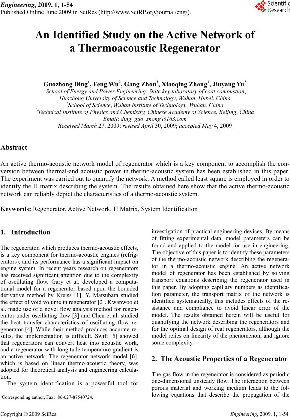 Engineering, 2009, 1, 1-54 Published Online June 2009 in SciRes (http://www.SciRP.org/journal/eng/). Copyright © 2009 SciRes. Engineering, 2009, 1, 1-54 An Identified Study on the Active Network of a Thermoacoustic Regenerator Guozhong Ding1, Feng Wu2, Gang Zhou3, Xiaoqin g Z ha ng1, Jiuyang Yu2 1School of Energy and Power Engineering, State key laboratory of coal combustion, Huazhong University of Science and Technology, Wuhan, Hubei, China 2School of Science, Wuhan Institute of Technology, Wuha n, China 3Technical Institute of Physics and Chemistry, Chinese Academy of Science, Beijing, China Email: ding_guo_zhong@163.com Received March 27, 2009; revised April 30, 2009; accepted May 4, 2009 Abstract An active thermo-acoustic network model of regenerator which is a key component to accomplish the con- version between thermal-and acoustic power in thermo-acoustic system has been established in this paper. The experiment was carried out to quantify the network. A method called least square is employed in order to identify the H matrix describing the system. The results obtained here show that the active thermo-acoustic network can reliably depict the characteristics of a thermo-acoustic system. Keywords: Regenerator, Active Network, H Matrix, System Identification 1. Introduction The regenerator, which produces thermo-acoustic effects, is a key component for thermo-acoustic engines (refrig- erators), and its performance has a significant impact on engine system. In recent years research on regenerators has received significant attention due to the complexity of oscillating flow. Gary et al. developed a computa- tional model for a regenerator based upon the bounded derivative method by Kreiss [1]. Y. Matsubara studied the effect of void volume in regenerator [2]. Kwanwoo et al. made use of a novel flow analysis method for regen- erator under oscillating flow [3] and Chen et al. studied the heat transfer characteristics of oscillating flow re- generator [4]. While their method produces accurate re- sults, the implementation is difficult. Swift [5] showed that regenerators can convert heat into acoustic work, and a regenerator with longitude temperature gradient is an active network. The regenerator network model [6], which is based on linear thermo-acoustic theory, was adopted for theoretical analysis and engineering calcula- tion. The system identification is a powerful tool for investigation of practical engineering devices. By means of fitting experimental data, model parameters can be found and applied to the model for use in engineering. The objective of this paper is to identify these parameters of the thermo-acoustic network describing the regenera- tor in a thermo-acoustic engine. An active network model of regenerator has been established by solving transport equations describing the regenerator used in this paper. By adopting capillary numbers as identifica- tion parameter, the transport matrix of the network is identified systematically, this includes effects of the re- sistance and compliance to avoid linear error of the model. The results obtained herein will be useful for quantifying the network describing the regenerators and for the optimal design of real regenerators, although the model relies on linearity of the phenomenon, and ignore so me complexity. 2. The Acoustic Properties of a Regenerator The gas flow in the regenerator is considered as periodic one-dimensional unsteady flow. The interaction between porous material and working medium leads to the fol- lowing equations that describe the propagation of the 1Corresponding aut h or, Fax:+86-027-87540724. 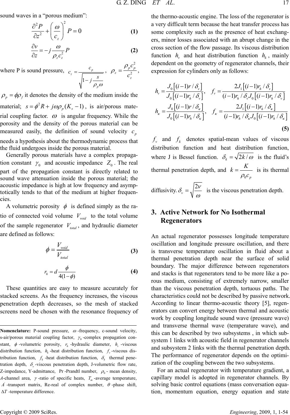 G. Z. DING ET AL. 17 Copyright © 2009 SciRes. Engineering, 2009, 1, 1-54 sound waves in a “porous medium”: 2 2 20 z PP zc (1) 2 zz v j P z c (2) where P is sound pressure, 1 p z p c c s j , 2 2 p p z z c c , p f it denotes the density of the medium inside the material; , is air/porous mate- rial coupling factor. 2(1 ps sRjK ) is angular frequency. While the porosity and the density of the porous material can be measured easily, the definition of sound velocity p c needs a hypothesis about the thermodynamic process that the fluid undergoes inside the porous material. Generally porous materials have a complex propaga- tion constant 0 and acoustic impedance 0 Z . The real part of the propagation constant is directly related to sound wave attenuation inside the porous material; the acoustic impedance is high at low frequency and asymp- totically tends to that of the medium at higher frequen- cies. A volumetric porosity is defined simply as the ra- tio of connected void volume to the total volume of the sample regenerator , and hydraulic diameter are defined as follow s: void V ltota V void total V V (3) 4(1 ) h rd (4) These quantities are easy to measure accurately for stacked screens. As the frequency increases, the viscous penetration depth decreases, so the mesh of stacked screens need be chosen with the resonance frequency of the thermo-acoustic engine. The loss of the regenerator is a very difficult term because the heat transfer process has some complexity such as the presence of heat exchang- ers, minor losses associated with an abrupt ch ange in the cross section of the flow passage. Its viscous distribution function v and heat distribution function k, mainly dependent on the geometry of regenerator channels, their expression for cylinders only as follows: h h 01 00 01 00 (1)/2 (1)/ , (1)/(1)/ (1)/ (1)/2 (1)/ , (1)/(1)/ (1)/ vh vv hvhv hv h hh Ji rJi r hf Ji ri rJi r Ji rJi r hf Ji ri rJi r v h (5) v f and k f denotes spatial-mean values of viscous distribution function and heat distribution function, where J is Bessel function. 2/ kk is the fluid’s thermal penetration depth, and 0 p K kc is its thermal diffusivity. 2 v is the viscous pen et rat i on depth. 3. Active Network for No Isothermal Regenerators An actual regenerator possesses longitude temperature oscillation and longitude pressure oscillation, and there is transverse temperature oscillation in fluid about a thermal penetration depth near the surface of solid boundary. The major difference between regenerators and stacks is that regenerators tend to be more like a po- rous medium, consisting of extremely narrow, smaller than the viscous penetration depth, tortuous paths. The characteristics could not be described by passive network. According to linear thermo-acoustic theory [5], regen- erators can convert energy between thermal and acoustic work by coupling longitude sound wave (pressure wave) and transverse thermal wave (temperature wave), and this can be described by two subsystems , in which sub- system 1 links with acoustic field in regen erator chan n els and subsystem 2 links with the thermal penetration depth. The performance of regenerator depends on the optimi- zation of the coupling between the two subsystems. Nomenclature: P-sound pressure, -frequency, c-sound velocity, s-air/porous material coupling factor, 0 -complex propagation con- stant, -volumetric porosity, -hydraulic diameter, -viscous distribution function, -heat distribution function, h rv h k hv f -viscous dis- tribution function, k f -heat distribution function, k thermal pene- tration depth, v -viscous penetration depth, J-volumetric flow rate, Z-impedance, Y-admittance, -Prandtl number, Pr 0 - mean density, A -channel area, -ratio of specific heats, -average temperature, m T ' A -transport matrix, Re-real of complex number, -phase shift, -temperature difference. T For an actual regenerator with temperature gradient, a capillary model is adopted in regenerator channels. By solving basic control equations (mass conversation equa- tion, momentum equation, energy equation and state 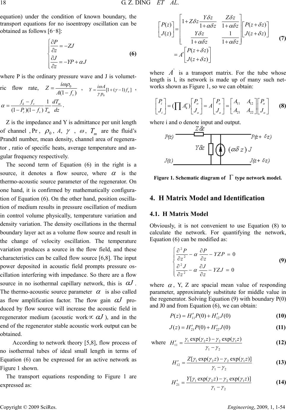 18 G. Z. DING ET AL. Copyright © 2009 SciRes. Engineering, 2009, 1, 1-54 equation) under the condition of known boundary, the transport equations for no isoentropy oscillation can be obtained as follows [6-8]: PZJ z JYP J z (6) where P is the ordinary pressure wave and J is volumet- ric flow rate, 0 (1 ) v i Z A f , 0 [1 (1)] iA Y pf , 1 (1 )(1) kv m rvm f fd PfTd T z . Z is the impedance and Y is admittance per unit length of channel ,, Pr 0 , A, , , are the fluid’s Prandtl number, mean density, channel area of regenera- tor , ratio of specific heats, average temperature and an- gular frequency respectively. m T The second term of Equation (6) in the right is a source, it denotes a flow source, where is the thermo-acoustic source parameter of the regenerator. On one hand, it is confirmed by mathematically configura- tion of Equation (6). On the other hand, position oscilla- tion of medium results in pressure oscillation of medium in control volume physically, temperature variation and density variation. The density oscillations in the thermal boundary layer act as a volume flow source and result in the change of velocity oscillation. The temperature variation produces a source in the flow field, and these characteristics can be called flow source [6,8]. The input power deposited in acoustic field prompts pressure os- cillation interfering with impedance. So there are a flow source in no isothermal capillary network, this is J . The thermo-acoustic source parameter is also called as flow amplification factor. The flow gain J pro- duced by flow source will increase the acoustic field in regenerator medium (acoustic workJ ), and in the end of the regenerator stable acoustic work output can be obtained. According to network theory [5,8], flow process of no isothermal tubes of ideal small length in terms of Equation (6) can be expressed for an active network as Figure 1 shown. The transport equations responding to Figure 1 are expressed as: 1 ()( ) 11 ()1( ) 11 () () Yz Zz Zz PzPz z zz J zYz Jz zz Pz z AJz z z o o P (7) where is a transport matrix. For the tube whose length is l, its network is made up of many such net- works shown as Figure 1, so we can obtain: ' A 11 12 21 22 () ioo k ioo PPP AA AA AA J JJ J (8) where i and o denote input and output. Figure 1. Schematic diagram of type network model. 4. H Matrix Model and Identification 4.1. H Matrix Model Obviously, it is not convenient to use Equation (8) to calculate the network. For quantifying the network, Equation (6) can be modified as: 2 2 2 2 0 0 PP YZP z z JJ YZJ zz (9) where , Y, Z are spacial mean value of responding parameter, approximately substitute for middle value in the regenerator. Solving Equation (9) with boundary P(0) and J0 and from Equatio n (6), we can obtain: 11 12 ()(0) (0)PzH PHJ (10) 21 22 ()(0) (0) J zHP HJ (11) where 1221 11 12 exp()exp( )z Hz (12) 1221 12 12 [ exp()exp()] Z z H z (13) 1221 21 12 [ exp()exp()]Yz H z (14) 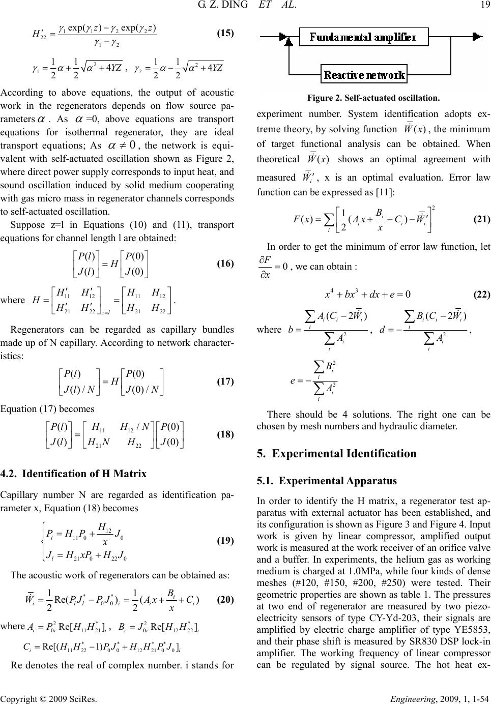 G. Z. DING ET AL. 19 Copyright © 2009 SciRes. Engineering, 2009, 1, 1-54 112 2 22 12 exp()exp()z H z (15) 2 111 4 22 YZ , 2 211 4 22 YZ According to above equations, the output of acoustic work in the regenerators depends on flow source pa- rameters . As =0, above equations are transport equations for isothermal regenerator, they are ideal transport equations; As 0 , the network is equi- valent with self-actuated oscillation shown as Figure 2, where direct power supply corresponds to input heat, and sound oscillation induced by solid medium cooperating with gas micro mass in regenerator channels corresponds to self-actuated oscillation. Suppose z=l in Equations (10) and (11), transport equations for channel length l are obtained: (16) () (0) () (0) Pl P H Jl J where . 11 121112 21 2221 22 zl HH HH HHH HH Regenerators can be regarded as capillary bundles made up of N capillary. Accord ing to network character- istics: () (0) ()/ (0)/ Pl P H J lNJ N (17) Equation (17) becomes (18) 11 12 21 22 / () (0) () (0) HHN Pl P HN H Jl J 4.2. Identification of H Matrix Capillary number N are regarded as identification pa- rameter x, Equation (18) becomes 12 11 00 21022 0 l l H PHP J x J HxP HJ (19) The acoustic work of regenerators can be obtained as: ** 00 11 Re() () 22 i illii B WPJPJAx x i C 1i i (20) where , 2* 0112 Re[ ] ii AP HHi2* 01 222 Re[ ] ii BJ HH **** 11 22001221 00 Re[( 1)] i CHHPJHHPJ Re denotes the real of complex number. i stands for Figure 2. Self-actuated oscillation. experiment number. System identification adopts ex- treme theory, by solving function ()Wx , the minimum of target functional analysis can be obtained. When theoretical ()Wx shows an optimal agreement with measured i W , x is an optimal evaluation. Error law function can be expressed as [11]: 2 1 () () 2i ii i B FxAxC W xi (21) In order to get the minimum of error law function, let 0 F x , we can obtain : 43 0xbxdxe (22) where 2 (2) ii i i i i A CW bA , 2 (2 ii i i i i BC W dA ) , 2 2 i i i i B e A There should be 4 solutions. The right one can be chosen by mesh numbers and hydraulic diameter. 5. Experimental Identification 5.1. Experimenta l A pparatus In order to identify the H matrix, a regenerator test ap- paratus with external actuator has been established, and its configuration is shown as Figure 3 and Figure 4. Input work is given by linear compressor, amplified output work is measured at the work receiver of an orifice valve and a buffer. In experiments, the helium gas as working medium is charged at 1.0MPa, while four kinds of dense meshes (#120, #150, #200, #250) were tested. Their geometric properties are shown as table 1. The pressures at two end of regenerator are measured by two piezo- electricity sensors of type CY-Yd-203, their signals are amplified by electric charge amplifier of type YE5853, and their phase shift is measured by SR830 DSP lock-in amplifier. The working frequency of linear compressor can be regulated by signal source. The hot heat ex-  20 G. Z. DING ET AL. Copyright © 2009 SciRes. Engineering, 2009, 1, 1-54 changer consists of 15mm chinaware with an electrical heater. The length of regenerator is 50mm, the cold heat exchanger consists of 30mm copper shell tube exch anger. The corresponding working frequency is 282Hz. where is oscillating pressure behind the valve, is the entrance pressure in the network, and their phase shift is 1, in p1,c p . This is a lumped parameter RLC model for measure- ment of acoustic work, its calculation is independent of temperature of network components. In order to measure the output acoustic work, a small orifice valve and compliance are needed. Then 11,c m iV UiCp p p The pressure and volumetric flow rate measurement of regenerator inlet and outlet adopt two sensors method. The pressures between two ends of regenerator are measured by two pressure sensors. The acoustic power flow entering the regenerator is determined by reference [9] and [10]. 1,c (23) 21,11, 1,1,1, 1Re[ ]Im[]sin 22 2 inin cinc mm VV WpUpp pp pp (24) Work input Cold HEX Work out put Regenerator Work T ransfer tube Cold HEX Computer Measurement System Hot HEX Figure 3. Schematic diagram of the experimental system. Figure 4. Experimental apparatus for system identification of regenerator.  G. Z. DING ET AL. 21 Copyright © 2009 SciRes. Engineering, 2009, 1, 1-54 Table 1. Geometric properties of regenerator Specimens (regenerator length=50mm,inner diameter=22mm). Type of wire screen Mesh num- ber/cm Hole diame- ter(mm) Wire diame- ter(mm) Porosity (%) Hydraulic diame- ter(um) 80 31.5 0.198 0.12 70.3 71.1 120 47.2 0.132 0.08 70.3 47.4 150 59.1 0.104 0.065 69.8 37.7 200 78.7 0.074 0.053 67.2 27.2 The stacked screen is made up of #200 wire meshes (Table 1), its porosity is 0.672, and the temperature dif- ference between the two ends of regenerator is 226K (the whole experimental range is 220K~400K), and the oscillating frequency dependence can be found in Ref- erence [9]. 5.2. Experimental Results Based on the experiment, the relation between the capil- lary number and wire meshes is shown as Figure 5 ac- cording to Equation (22). The calculated data and meas- ured data of output acoustic work in regenerator after identification are shown as Figure 6 (for meshes #200). The error in the dimension measurements is less than 1.0%. The thermocouples with an accuracy of 0.75% are utilized to measure both fluid and wall temperature. The error between measured and calculated acoustic work is less than 3% according to Figure 6. The output acoustic work and COPR of regenerators for different wire meshes are shown as follows: From Figure 7, the length of regenerators need be chosen accurately. The meshes of regenerators must match with the working frequency of thermo-acoustic engines. 80100 120 140 160 180 200 150 200 250 300 350 400 450 500 024681 0 2 4 6 8 10 0 x(capillary number) wire meshes Figure 5. The relation of the identified capillary number and wire meshes. 300 320 340 360 380 400 420 440 460 16 18 20 22 24 26 28 30 32 34 36 02468 0 2 4 6 8 10 10 the output acoustic work(W) temperat ure difference(K) calculation experiment Figure 6. The relation of the output work and temperature difference of regenerator. 0.00 0.01 0.020.030.04 0.050.060.070.08 0.09 0.10 0 10 20 30 40 50 60 70 80 the output acoustic work(W) the length of regenerator(m) 80 mesh 120mesh 150mesh 200mesh 0.00 0.01 0.02 0.03 0.04 0.05 0.06 0.07 0.08 0.09 0.10 0.00 0.05 0.10 0.15 0.20 0.25 0.30 0.35 0.40 0.45 0.50 COPR the length of regenerat or 80 mesh 120mesh 150mesh 200mesh Figure 7. The output acoustic work and COPR of regenerators.  22 G. Z. DING ET AL. Copyright © 2009 SciRes. Engineering, 2009, 1, 1-54 6. Conclusions The lumped parameter H matrix of regenerator network is derived by establishing an active thermo-acoustic network model of regenerator, and identification pa- rameters using capillary number N of system network are identified. The calculated results and measured data of output acoustic work in regenerators show a well agreement by identifying H matrix. The identified H matrix provides convenience for engineering calculation of regenerator, and provided a basis for whole network of thermo-acoustic engines. 7. Acknowledgements The paper is supported by the Natural Science Fund of P. R. China (project No. 50676068). 8. References [1] J. Gary, D. E. Pancy, and R. Radebaugh, “A computa- tional model for a regenerator,” in: Proceedings of Third Cryocooler Conference, NIST Special Publication, Vol. 698, pp.199-211, 1985. [2] Y. Matsubara, “Effect of void volume in regenerator,” in: Proceedings of The Sixth International Cryocooler Con- ference, 1990. [3] K. Nam and S. Jeong, “Novel flow analysis of regenera- tor under oscillating flow with pulsating pressure,” Cryogenics, Vol. 45, pp. 368-379, 2005. [4] Y. Y. Chen, E. C. Luo, and W. Dai, “Heat transfer charac- teristics of oscillating flow regenerator filled with circular tubes or parallel plates,” Cryogenics, Vol. 47, pp. 40-48, 2007. [5] G. W. Swift, “Thermoacoustic engines,” Journal of the Acoustical Society of America, Vol. 84, No. 4, pp. 1145-1179, 1988. [6] X. H. Deng, “Thermoacoustic theory of regenerator and design theory for thermoacoustic engine [D],” Wuhan: Huazhong University of Science and Technology, 1994. [7] F. Wu, et al., “Active network modeling for regenerator cryocooler [A],” Proceedings of Symposium on Energy Engineering in the 21st Century [C], Begell House New York, Wallingford, 2000. [8] F. Z. Guo, “Dynamic heat transfer [M],” Wuhan: Huazhong University of Science and Technology Press, 1997. [9] Q. Tu, Q. Li, F. Wu, and F. Z. Guo, “Network model ap- proach for calculating oscillating frequency of ther- moacoustic prime mover,” Cryogenic, Vol. 43, pp. 351- 357, 2003. [10] Q. Tu, C. Wu, Q. Li, F. Wu, and F. Z. Guo, “Influence of temperature gradient on acoustic characteristic parame- ters of stack in TAE,” International Journal of Engineer- ing Science, Vol. 41, pp. 1337-1349, 2003. |