Z. MANSUROV
Copyright © 2013 SciRes. MSCE
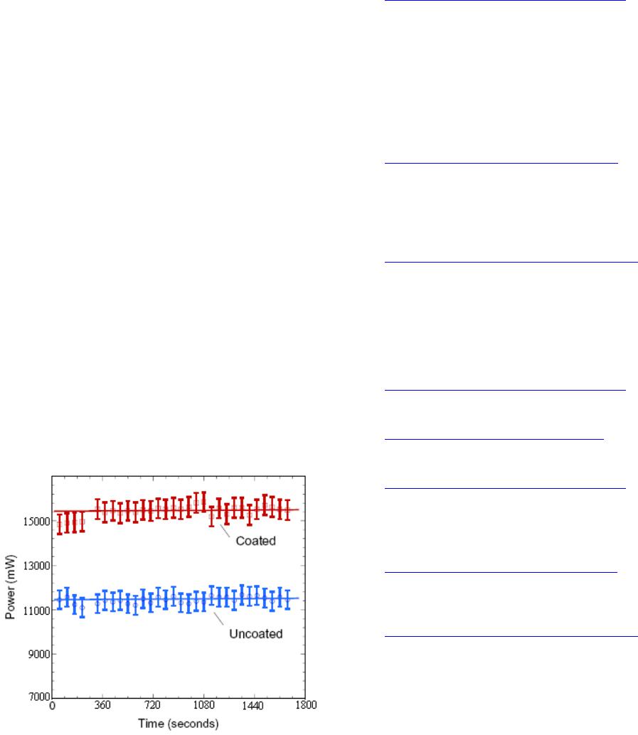
Power output of uncoated vs. coated solar cell with high
concentration of nickel oxide/methanol suspension. Bars
indicate a 95% confidence interval for measured values
(Figure 8).
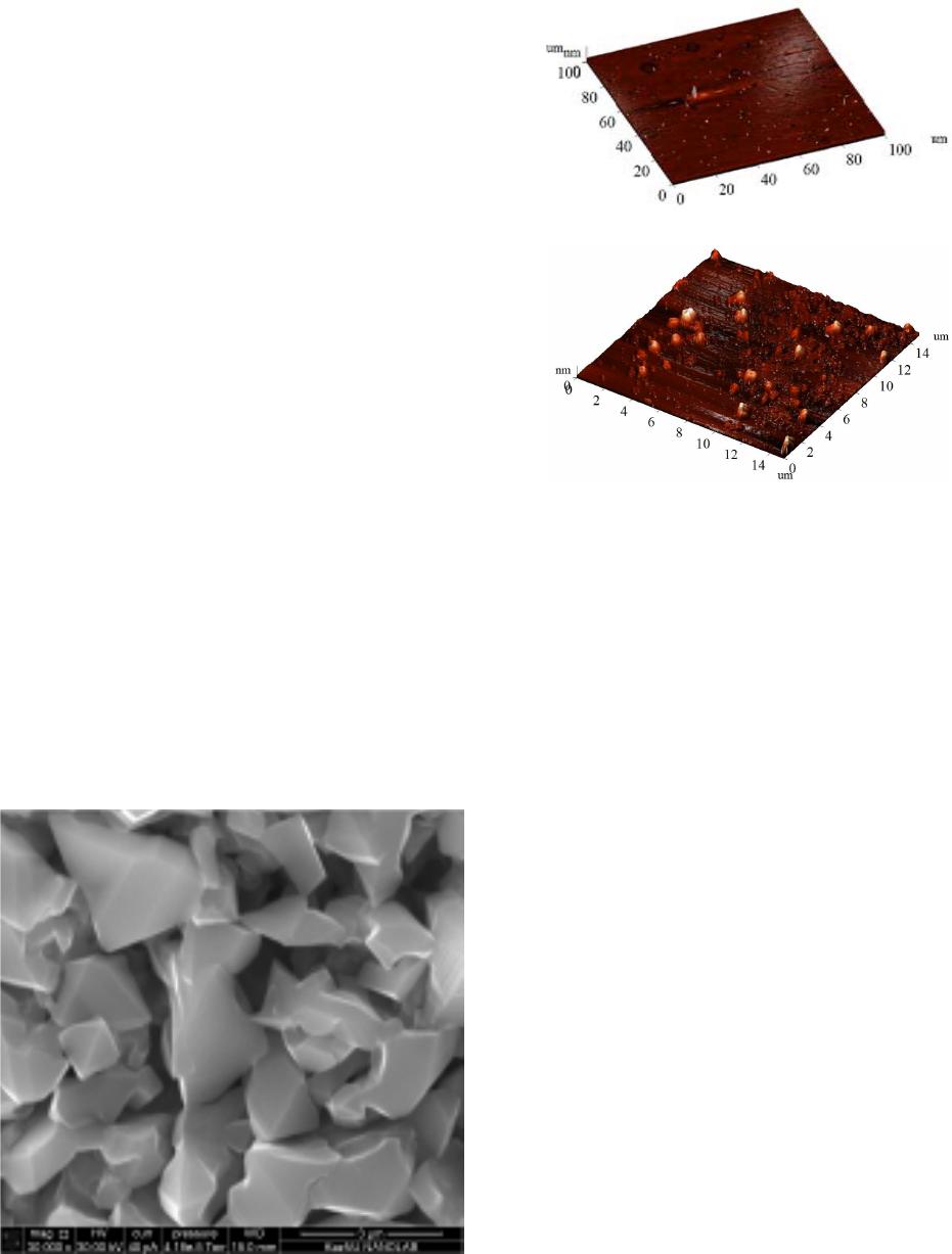
The wavelength dependent light transmission of the
coating applied to the surface of the solar element is of a
great importance for its effective work. The spectra of
the transmission of the coating based on nickel oxide
nanoparticles to the surface of quartz substrate with the
concentration of 8 × 10⁴ particle/cm2 were recorded in a
wavelength range from 400 to 1100 nm. The analysis
shows that in a short-wave region a slight decrease is
observed, because of light absorption in nanostructures
whereas in visible and long-wave regions transmission
coefficient reaches 93%.
Open-circuit voltage increased to 4% - 7%, the short-
circuit current increased to 20% - 28%, efficiency of the
solar cells increased by 2% to 3%, at a fill factor of the
element being equal to 0.75. The absence of other factors
which may cause the increase of the output power of the
solar cells means that original cause is the application of
nanoparticles.
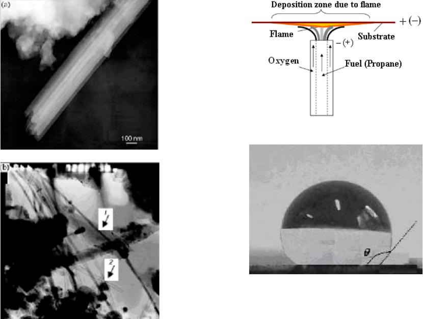
We would like to note uniqueness of using the counter
flow of the burner to the opposing jets for the synthesis
of nanomaterials, which was created by Potter [15] and
Weinberg [16] to study the structure of the flame front.
Diffusion burner on the counter flow can be effec-
tively used for the production of carbon nanotubes in the
synthesis of the fuel, as well as for the introduction of
metal oxide nichrome wire into the zone of oxygen sup-
ply.
Figure 8. Power output of uncoated vs. coated solar cell
with high concentration of nickel oxide/methanol suspen-
sion.
REFERENCES
[1] J. J. Thomson, “LVIII. On the Masses of the Ions in
Gases at Low Pressures,” Philosophical Magazine Series
5, Vol. 48, No. 295, 1899, pp. 547-567.
http://dx.doi.org/10.1080/14786449908621447
[2] H. A. Wilson, “The Electrical Properties of Flames and
Incandescent Solids,” University Press, London, 1912.
[3] K. H. Homann and H. G. Wagner, “Some Aspect of Soot
Formation,” In: J. Ray Bawen, Ed., Dynamics of Exo-
thermicity (Combust. Sc. Techol. Book Series, Vol. 2),
Carbon and Breach Publishers, 1996, pp. 151-184.
[4] Z. A. Mansurov, “Soot Formation in Combustion Proc-
esses (Review),” Combustion, Explosion and Shock
Waves, Vol. 41, No. 6, 2005, pp. 727-744.
http://dx.doi.org/10.1007/s10573-005-0083-2
[5] P. Gerhardt, S. Loffler and K. H. Homann, Proc. 22nd Int.
Symp. Combust., The Combustion Inst., Pittsburgh, 1988,
pp. 395-401.
[6] J. B. Howard, A. L. Lafleur, et al., Carbon, Vol. 30, 1992,
pp. 1183-1201.
http://dx.doi.org/10.1016/0008-6223(92)90061-Z
[7] Z. A. Mansurov, Combustion, Expolsion and Shock
Waves, Vol. 48, No. 5, 2012, pp. 561-569.
[8] W. Merchan-Merchan, A. V. Saveliev an d L. A. Kennedy,
“Flame Nanotube Synthesis in Moderate Electric Fields:
From Alignment and Growth Rate Effects to Structural
Variations and Branching Phenomena,” Carbon, Vol. 44,
2006, pp. 3308-3314.
http://dx.doi.org/10.1016/j.carbon.2006.06.025
[9] A. Levesque, V. T. Bin h, et al., Thin Solid Films, Vol.
464-465, 2004, pp. 308-314.
http://dx.doi.org/10.1016/j.tsf.2004.06.012
[10] S. Naha, S. Sen and I. K. Puri, Carbon, Vol. 45, 2007, pp.
1696-1716.
http://dx.doi.org/10.1016/j.carbon.2007.04.018
[11] Z. A. Mansurov, Advanced Materialials Research, Vol.
486, 2012, pp. 134-139
[12] H. Bockhorn, “Soot Formation in Combustion,” Springer,
Berlin/Heidelberg, 1994, p. 4.
http://dx.doi.org/10.1007/978-3-642-85167-4
[13] I. A. Kuznetsov, M. J. Greenfield, Y. U. Mehta, W. Mer-
chan-Merchan, G. Salkar and A. V. Saveliev, Applied
Energy, Vol. 88, 2011, pp. 4218-4221.
http://dx.doi.org/10.1016/j.apenergy.2011.04.033
[14] Z. A. Mansurov M. Auyelkhankyzy, B. T. Lesbayev, et al.
Advanced Materials Research, Vol. 486, 2012, pp 140-
144.
[15] A. E. Po tter, S. Heimel and J. N. Butler, 8th Symposium
(Int) on Combustion, 1962, pp. 1027-1034.
[16] T. P. Pandya and F. J. Wein berg, 9th Symposium (Int) on
Combustion, 1963, pp. 587-596.