 J. Biomedical Science and Engineering, 2013, 6, 71-83 JBiSE http://dx.doi.org/10.4236/jbise.2013.612A009 Published Online December 2013 (http://www.scirp.org/journal/jbise/) Effect of screw position on bone tissue differentiation within a fixed femoral fracture Saghar Nasr1,2, Stephen Hunt1,3, Neil A. Duncan1,3,4* 1McCaig Institute for Bone and Joint Health, Calgary, Canada 2Department of Mechanical & Manufacturing Engineering, Schulich School of Engineering, University of Calgary, Calgary, Canada 3Department of Orthopedic Surgery, University of Calgary, Calgary, Canada 4Department of Civil Engineering, Schulich School of Engineering, University of Calgary, Calgary, Canada Email: *duncan@ucalgary.ca Received 30 October 2013; revised 28 November 2013; accepted 17 December 2013 Copyright © 2013 Saghar Nasr et al. This is an open access article distributed under the Creative Commons Attribution License, which permits unrestricted use, distribution, and reproduction in any medium, provided the original work is properly cited. ABSTRACT Plate and screw constructs are routinely used in the treatment of long bone fractures. Despite consider- able advancements in technology and techniques, there can still be complications in the healing of long bone fractures. Non-unions, delayed unions, and hardware failures are common complications ob- served in clinical practice following open reduction and internal fixation of fractures [1]. Potential causes of these adverse clinical effects may be disruptive to the periosteal and endosteal blood supply, stress shielding effects, and inadequate mechanical stability. The goal of the present study was to explore the effect of screw position on the fracture healing and forma- tion of new bone tissue with mechanoregulatory algo- rithms in a computational model. An idealized poroe- lastic 3D finite element (FE) model of a femur with a 5 mm fracture gap, including a plate-screw construct was developed. Nineteen different plate-screw com- binations, created by varying the number and posi- tion of screws within the plate, were created to iden- tify a construct with the most favourable attributes for fracture healing. The first phase of the study evaluated constructs through mechanical stress analyses to identify those constructs with high load- support capability. The second phase of the study evaluated healing and bone formation with a biphasic mechanoregulatory algorithm to simulate tissue dif- ferentiation for fixation within selected constructs. The results of our analysis demonstrated a 4-screw symmetrical construct with the largest distance be- tween screws to provide the most favourable balance of stability and optimized conditions to pro mote frac- ture healing. Keywords: Femoral Fracture; Internal Fixation; Screw Number; Screw Position; Tissue Differentiation; Finite Element Analysis 1. INTRODUCTION The treatment of long bone fractures is a significant health problem, particularly for femoral fractures [2-5]. Although bone has outstanding mechanical properties and a remarkable ability to heal, in some cases healing is impaired or delayed [6,7]. Internal fixators have been used as the most common treatment technique for open and closed fractures [3,8-10]. Despite the advent of in- tramedullary fixation, there are still clinical indications for plating of long bone fractures (e.g., pulmonary com- plications, damage control orthopaedics, revision proce- dures, absence of X-ray, obliterated canal, small canal and periarticular fractures). The main goals of any or- thopaedic fixation technique are to maintain anatomic alignment, provide stability of the fracture to facilitate healing, and increase load bearing to facilitate rehabilita- tion [11]. Internal fixation is commonly a fracture span- ning plate with a combination of screws through the plate. The two main drawbacks of internal fixations are: 1) disruption of blood supply, and 2) shielding the under- lying bone and fracture gap from mechanical stresses. To overcome vascularisation issues and surgical exposure, orthopaedic hardware is installed with utmost care to protect soft tissues, and minimize soft tissue stripping in order to lessen devascularisation of bone [3,10,11]. One technique to minimize vascular damage to bone includes reducing the number of screws used to anchor the plate to bone [12]. Reducing the number of screws may not significantly affect the structural stiffness of the fracture, but may increase the strain at the fracture site [12]. Fur- thermore, the mismatch between bone and plate stiffness *Corresponding author. OPEN ACCESS  S. Nasr et al. / J. Biomedical Science and Engineering 6 (2013) 71-83 72 can cause stress shielding which may lead to complica- tions of bone resorption and focal osteoporosis [13-16]. A comprehensive and algorithmic approach to selecting screw type and configuration may minimize the delete- rious effects of screw installation, provide mechanical and biological insight on the contributions of screw type and position, and provide an evidence-based justification for surgical technique. It is our hope that this will pro- vide the basis for further advancement of open reduction and internal fixation techniques for fracture care. Empirical and computational data support that me- chanical stimulation of bone is an important factor in bone healing [17-20]. A number of different mech- anoregulatory algorithms have been developed and are generally classified into 1) single-solid phase and 2) bi- phasic algorithms. These algorithms are regulated by one or two mechanical stimuli, which may include inter- fragmentary gap movement, octahedral shear strain, hy- drostatic stress, fluid velocity and fluid shear stress [17,18,21-24]. Isaksson et al. (2006) compared tissue dif- ferentiation patterns in a finite element model (FE) of an ovine tibia implementing different proposed algorithms [17]. The computational predictions were then validated against experimental observations in vivo. The biphasic algorithm proposed by Lacroix and Prendergast (2002) was found to most closely model experimental observa- tions [17]. The biphasic algorithm has been widely used to investigate skeletal tissue repair [17,23, 25-32], and thus we selected this biphasic algorithm to predict tissue differentiation in our analyses. Prediction of the bone mechanobiology conditions at the fracture site has been previously investigated to op- timize fixation constructs [33-35]. Kim et al. (2012) used a single-solid phase mechanoregulatory model regulated by deviatoric tissue strain to predict tissue differentiation in a 3D idealized fracture tibia using plates with different material properties. The carbon/epoxy composite plate was found to highly promote tissue differentiation [35]. Son and Chang (2013) used the same single-solid phase mechanoregulatory algorithm as Kim et al. (2012) to predict the healing process in idealized 3D tibia models with different oblique fractures [34]. It was observed that the plate material (stiffness) that should be used was highly dependent on the angle of the fracture. The car- bon/epoxy composite plate had the highest healing rate when the fracture angle was lower than 25˚, whereas for higher angles, the glass/polypropylene composite plate led to more bone formation [34]. Dubov et al. (2011) explored optimal cable-screw po- sitioning in femoral fracture models using an eight screw-hole plate and six screws (using 2 screws in the proximal femur). The stability and biomechanical per- formance of different cable-screw constructs were com- putationally predicted, and then validated against ex- perimental results [10]. The femur was modelled as an elastic material and quasi-static loads were applied to one end while the other end was fixed. The construct experiencing the least von Mises stress values at the screws, plate and bone was selected as the optimal struc- ture. However, to the best of our knowledge, no studies have been performed to predict tissue differentiation within the fracture for different bone-screw assemblies. With the advancement of minimally invasive surgical techniques, optimal screw configuration may influence surgical technique and equipment design. The prevalence of orthopaedic joint replacements has resulted in a sig- nificant increase in the incidence of periprosthetic frac- tures. The limited space and bone available for fixation with plate and screw constructs present the orthopaedic surgeon with considerable operative challenges. Better understanding of the optimal screw number and position has the potential to advance fracture care in these situa- tions [36,37]. Improper screw spacing and number may result in non-ideal mechanical conditions and consequently, dis- rupted healing and cell apoptosis [38-40]. Hence, predic- tion of the mechanical environmental and tissue differen- tiation may help us to obtain a better understanding of the optimal screw number and position. This knowledge can improve internal fixation techniques to better prevent non-unions and accelerate the healing process. Therefore, the objective of this study was to evaluate the effect of internal fixation configuration on the mechanical stabil- ity and the healing progression for a transverse femoral fracture. We varied the screw positions within a standard orthopaedic plate installed across a 5 mm fracture gap [10] and identified a construct that provided the most favourable mechanical and mechanobiological condi- tions for healing. This systematic computational analysis can contribute to an evidence-based justification of op- timal plate-screw combination and can provide important mechanical performance guidelines for surgical tech- nique and product selection. 2. METHODS An idealised 3D finite element model of a human femur with a 5 mm fracture gap [10] was developed (ABAQUS v6.11, Simulia, USA) to represent a transverse fracture in the femoral shaft (Figure 1). The femur was modelled as an outer cortical layer and an inner trabecular core with diameters of 32 mm and 16 mm, respectively [10]. The fracture gap was assumed to be initially filled with a scaffold consisting of stem-cell-seeded granulation tissue. To model the internal fixation, a 3.5 mm Low Contact- Dynamic Compression Plate (LC-DCP, Synthes, Paoli, PA, USA) containing eight screw-holes with uniform spacing was created (Figure 1). LC-DCPs are mainly used for fractures in long bones and have minimal direct Copyright © 2013 SciRes. OPEN ACCESS 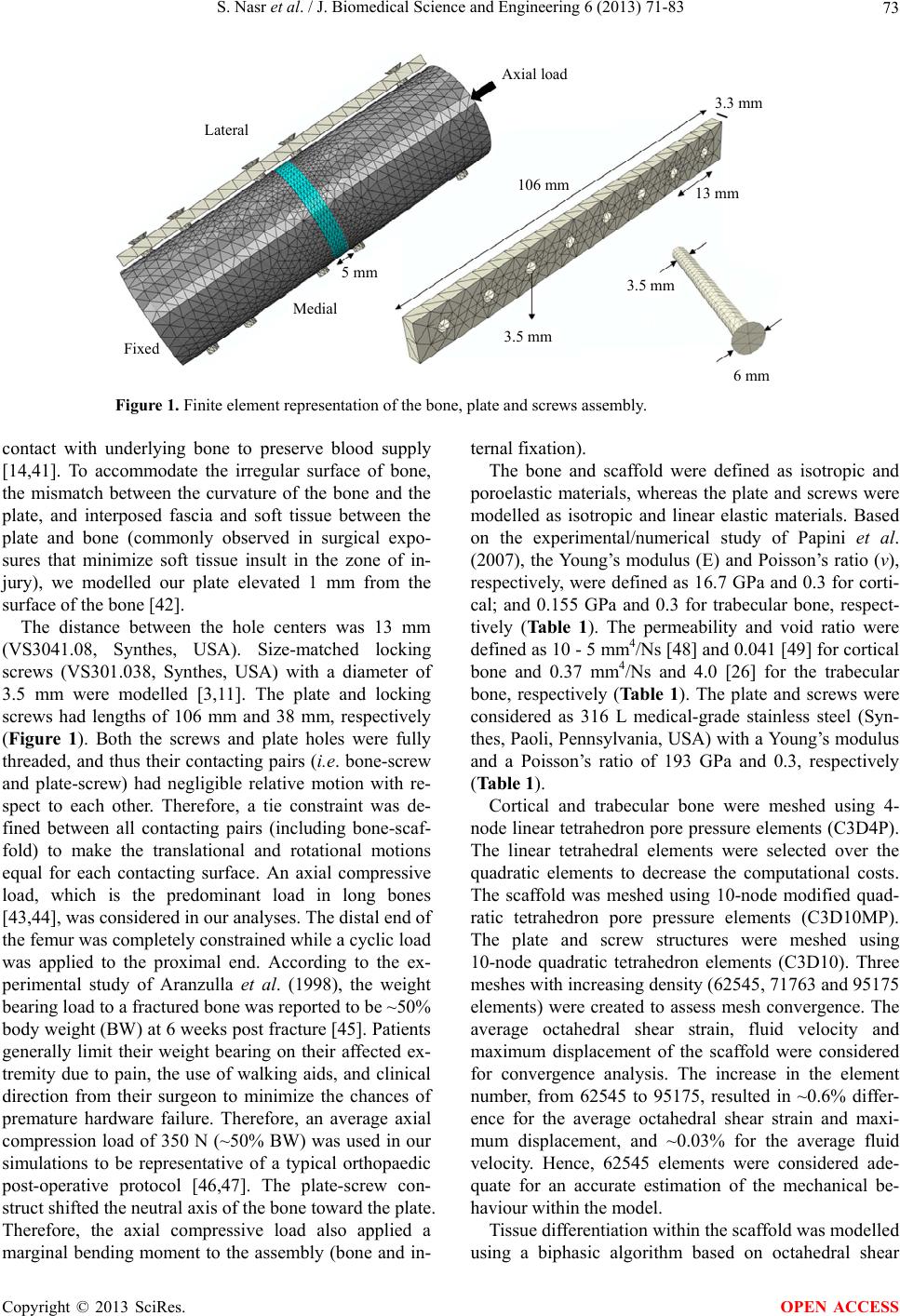 S. Nasr et al. / J. Biomedical Science and Engineering 6 (2013) 71-83 Copyright © 2013 SciRes. 73 Lateral Axial load Fixed Medial 5 mm 106 mm 3.5 mm 3.5 mm 13 mm 3.3 mm 6 mm Figure 1. Finite element representation of the bone, plate and screws assembly. contact with underlying bone to preserve blood supply [14,41]. To accommodate the irregular surface of bone, the mismatch between the curvature of the bone and the plate, and interposed fascia and soft tissue between the plate and bone (commonly observed in surgical expo- sures that minimize soft tissue insult in the zone of in- jury), we modelled our plate elevated 1 mm from the surface of the bone [42]. The distance between the hole centers was 13 mm (VS3041.08, Synthes, USA). Size-matched locking screws (VS301.038, Synthes, USA) with a diameter of 3.5 mm were modelled [3,11]. The plate and locking screws had lengths of 106 mm and 38 mm, respectively (Figure 1). Both the screws and plate holes were fully threaded, and thus their contacting pairs (i.e. bone-screw and plate-screw) had negligible relative motion with re- spect to each other. Therefore, a tie constraint was de- fined between all contacting pairs (including bone-scaf- fold) to make the translational and rotational motions equal for each contacting surface. An axial compressive load, which is the predominant load in long bones [43,44], was considered in our analyses. The distal end of the femur was completely constrained while a cyclic load was applied to the proximal end. According to the ex- perimental study of Aranzulla et al. (1998), the weight bearing load to a fractured bone was reported to be ~50% body weight (BW) at 6 weeks post fracture [45]. Patients generally limit their weight bearing on their affected ex- tremity due to pain, the use of walking aids, and clinical direction from their surgeon to minimize the chances of premature hardware failure. Therefore, an average axial compression load of 350 N (~50% BW) was used in our simulations to be representative of a typical orthopaedic post-operative protocol [46,47]. The plate-screw con- struct shifted the neutral axis of the bone toward the plate. Therefore, the axial compressive load also applied a marginal bending moment to the assembly (bone and in- ternal fixation). The bone and scaffold were defined as isotropic and poroelastic materials, whereas the plate and screws were modelled as isotropic and linear elastic materials. Based on the experimental/numerical study of Papini et al. (2007), the Young’s modulus (E) and Poisson’s ratio (ν), respectively, were defined as 16.7 GPa and 0.3 for corti- cal; and 0.155 GPa and 0.3 for trabecular bone, respect- tively (Table 1). The permeability and void ratio were defined as 10 - 5 mm4/Ns [48] and 0.041 [49] for cortical bone and 0.37 mm4/Ns and 4.0 [26] for the trabecular bone, respectively (Ta b l e 1 ). The plate and screws were considered as 316 L medical-grade stainless steel (Syn- thes, Paoli, Pennsylvania, USA) with a Young’s modulus and a Poisson’s ratio of 193 GPa and 0.3, respectively (Table 1). Cortical and trabecular bone were meshed using 4- node linear tetrahedron pore pressure elements (C3D4P). The linear tetrahedral elements were selected over the quadratic elements to decrease the computational costs. The scaffold was meshed using 10-node modified quad- ratic tetrahedron pore pressure elements (C3D10MP). The plate and screw structures were meshed using 10-node quadratic tetrahedron elements (C3D10). Three meshes with increasing density (62545, 71763 and 95175 elements) were created to assess mesh convergence. The average octahedral shear strain, fluid velocity and maximum displacement of the scaffold were considered for convergence analysis. The increase in the element number, from 62545 to 95175, resulted in ~0.6% differ- ence for the average octahedral shear strain and maxi- mum displacement, and ~0.03% for the average fluid velocity. Hence, 62545 elements were considered ade- quate for an accurate estimation of the mechanical be- haviour within the model. Tissue differentiation within the scaffold was modelled using a biphasic algorithm based on octahedral shear OPEN ACCESS  S. Nasr et al. / J. Biomedical Science and Engineering 6 (2013) 71-83 74 Table 1. Mechanical properties of the tissue and internal fixation materials [26,48,49]. Femur Scaffold Internal fixation Cortical Trabecular Granulation Fibrous tissue Cartilage Bone Plate/Screw Young’s modulus [GPa] 16.7 0.155 0.0002 0.002 0.01 1 - 6 193 Poisson’s ratio 0.3 0.3 0.167 0.167 0.167 0.3 0.3 Permeability [mm4/Ns] 10−5 0.37 0.01 0.01 0.005 0.1 - 0.37 - Void ratio 0.041 4.0 4.0 4.0 4.0 4.0 - strain () and interstitial fluid velocity ( oct ε v) [24,25]: 00370003 oct f εv S.. . (1) High values for mechanical stimulus (S) promote the differentiation of cells into fibrous tissues (3 < S < 6), intermediate values stimulate cartilage differentiation (1 < S < 3), and low levels lead to formation of immature (0.267 < S < 1), and mature bony tissue (0.011 < S < 0.267). For each element, differentiation and the formation of bone tissue was simulated by a gradual change of mate- rial properties over time. The initial cellular tissue gradu- ally differentiated into fibrous tissue, immature and ma- ture cartilage, and immature and mature bone depend- ing on the local mechanical environment. A user defined FORTRAN subroutine, USDFLD, was developed to up- date the material properties based on the average of computed mechanical stimulus (S) in the previous 10 steps (weeks) [34,35]. In each step, the mechanical stim- uli were calculated at the point of maximum loading, and a cyclic compressive load of 350 N was applied to the proximal end of femur. One loading step was considered as a surrogate for one week of healing [34,35], and the applied load represented the average load that was ap- plied to the bone during one week of healing [34,35]. To investigate the effect of screw spacing on the me- chanical stability of the fracture and bone healing proc- ess, nineteen distinct constructs were created (Figure 2). The models were composed of (a) eight screws: C1 (Figure 2); (b) seven screws: C2, C3; (c) six screws: C4, C5, C6, C2a, C2b, C3a and C3b; (d) five screws: C4a, C5a and C6a; (e) four screws: C4b, C5b and C6b; and (f) two screws: C7, C8 and C9 (Figure 2). Considering all models illustrated in Figure 2: (1) in each column, the number and location of screws in the proximal femur are held fixed, whereas variations are applied to the screws in the distal femur; (2) in the first two rows, the number and location of the screws in the distal femur are held fixed, whereas variations are applied to the screws in the proximal femur; and (3) the configurations of third and fourth rows are symmetric about the center line passing through the fracture zone. Note that each column in Fig- ure 2 is called “a family of constructs” in the rest of the paper. Figure 2. Constructs representing different screw combina- tions. The cortical bone, trabecular bone and scaffold are shown in dark grey, green and orange, respectively. The screws are numbered starting from the proximal end as shown in construct C1. The arrows show the sequential change in each family of constructs. A number of experimental/numerical studies [50-53] have shown that bone fails by brittle fracture. Schileo et al. (2008) computationally predicted the location of ca- daver femur fractures using the maximum principal stress, maximum von Mises stress and maximum strain criteria in comparison to experimental observations (i.e., the load-displacement curves and high-speed movies) [50]. Comparing the computational predictions to the experimental observations, they observed that the strain criterion better predicted the risk of bone fracture and its location [50]. In the present study, the maximum princi- pal strain and von Mises criteria were both used to dis- tinguish the models with lower risk of fracture and higher load-support capabilities [10,50,54]. Ultimate compressive and tensile strains of 0.0104 and 0.0073, Copyright © 2013 SciRes. OPEN ACCESS  S. Nasr et al. / J. Biomedical Science and Engineering 6 (2013) 71-83 75 respectively, for bone were adopted from the experiment- tal study of Bayraktar et al. (2004) [54]. Lastly, the bone was subjected to a cyclic compressive loading and bone formation was predicted implementing the biphasic mechanoregulatory algorithm into the nominated models with lower risk of failure (from phase I). Tissue distribu- tion and average stiffness of the scaffold at the fracture gap were then compared in the nominated models over the healing period, and the optimal plate-screw construct with the best balance of stability and bone healing capa- bility was selected. 3. RESULTS 3.1. Mechanical Environment within the Internal Fixation, Femoral Bone and Fracture Site Stresses were in general higher in the screws compared to the plate. A maximal von Mises stress of ~473 MPa was found for the screws in the 4-screw construct C6b (fourth screw position), whereas it was only ~226 MPa for the surrounding plate (fourth screw-hole) (Figures 3(a) and (c)). The magnitude of von Mises stress within the plate was greatest between the lowermost screws in the proximal femur and the uppermost screws in the dis- tal femur. For example, in construct C6b the region of maximum von Mises stress (i.e. ~192 - 226 MPa, Figure 3(a)) was located between the fourth and fifth plate screw-holes. A stress concentration was observed in the vicinity of the screw-holes in the femoral bone, whereas the stress was almost uniformly distributed elsewhere (e.g. C6b, Figure 3(c)). The maximum femoral stress was found around the lowermost screw-hole in the proximal femur. The construct that had every plate hole filled with a screw (C1), demonstrated increased overall stiffness and decreased magnitude of stress and strain compared to other constructs (Figures 4(a)-(d)). In contrast, con- structs with only two screws (C7, C8, and C9) experi- enced significantly greater stress magnitudes, i.e. ~490 - 550%, compared to the fully-screwed femur (Figure 4(a)). However, the stress fields in C1 were not signify- cantly different from those of 7-screw constructs (i.e. C2 and C3, Figure 4(a)). Consequently, since the stress dis- tribution was insensitive between C1, C2 and C3, the numberof screws was reduced to six. The peak principal stress values in the femur were relatively higher in the 6-screw constructs with two screws above the fracture (i.e. C4, C5 and C6, Figure 4(a)) compared to the ones with three screws above the fracture (i.e. C2a, C2b, C3a and C3b, Figure 4(a)). In each construct family (Family of C2, C3, C4, C5 and C6, Figure 4(a)); screw omis- sions resulted in marginal changes in the level of prince- pal stress in the femur (Figure 4(a)). For instance, for the construct family of C5 (i.e. C5, C5a and C5b with 6, 5 Figure 3. Distribution of von Mises stress within C6b con- struct: (a) Plate, (b) Femur and (c) Screws located at the first, fourth, fifth and eighth screw-holes. (a, b) The zone between the fourth and fifth screw-holes, located above and below the fracture gap, experienced higher stress magnitudes compared to the other holes. (a, b) The femur experienced less von Mises stress compared to the plate. (a, b) Stress concentration can also be observed around the femur screw-holes. The scale bars are 5 mm. and 4 screws), the maximum principal stress was 8653 kPa, 8779 kPa and 9201 kPa for C5, C5a and C5b, re- spectively (maximum difference was ~6.3%). However, the screw position resulted in a considerable difference in the stress magnitudes. For instance, the maximum prin- cipal stress was 9201 and 7610 kPa for 4-screw con- structs C5b and C6b, respectively (maximum difference was ~20.9%). Among the 4-screw constructs, the femur of C5b ex- perienced larger principal strains compared to either C4b or C6b (Figure 5). The strain was lower within C6b and also more uniformly distributed throughout the length of the femur compared to C4b construct (Figures 5(a) and 5(c)). The maximum and minimum principal strains were lower than the limit values of the principal strains crite- rion (see Method section). For instance, the minimum principal strain values were −0.00087, −0.00129 and −0.00072 for 4-screw constructs C4b, C5b and C6b, re- spectively (Figure 5). In the 2-screw models (i.e. C6, C7 and C8), under 350 N axial compression load, the maxi- mum principal strains were ~0.001 which is about 100 fold greater than the strains in the 4-screw constructs, but slightly less than the limit values (~0.0073) of the frac- ture criterion. The prediction of maximum interfragmentary move- ment (u), average of octahedral shear strain (oct ) and fluid velocity ( ε v) at the fracture site (scaffold) revealed hat both the number and position of screws affect the t Copyright © 2013 SciRes. OPEN ACCESS  S. Nasr et al. / J. Biomedical Science and Engineering 6 (2013) 71-83 Copyright © 2013 SciRes. 76 0.6 0.5 0.4 0.3 0.2 0.1 0 Max. principal strees [MPa] C2 Family C3 Family C4 Family C5 Family C6 Family (a) (b) (c) (d) Max. interfragmentary Movement [mm] 0.18 0.15 0.12 0.09 0.06 0.03 0 Avg. fluid velocity [m/s] Avg. octahedral shear strain [%] 18 15 12 9 6 3 0 30 25 20 15 10 5 0 C1 C5 C2 C5a C2a C5b C2b C6 C3 C6a C3a C6b C3b C7 C4 C8 C4a C9 C4b Figure 4. (a) The peak magnitudes of principal stress within the femur, (b) Maximum interfragmentary movement, (c) Average fluid velocity within the scaffold, and (d) Average octahedral shear strain within the scaffold. C4b C5b C6b 0.00000 −0.00012 −0.00024 −0.00036 −0.00048 −0.00060 −0.00072 −0.00087 0.00000 −0.00012 −0.00024 −0.00036 −0.00048 −0.00060 −0.00072 −0.00129 0.00000 −0.00012 −0.00024 −0.00036 −0.00048 −0.00060 −0.00072 (c)(b) (a) Figure 5. Distributions of principal strains within the midsection of the proximal femur are shown for (a) C4b, (b) C5b and (c) C6b constructs. The scale bar is 5 mm. mechanical environment (Figures 4(b)-(d)). The fully- screwed construct C1 and the family of C3 (7 and 6- screw) had the smallest values of u, oct and ε v (av- erage) among the constructs: ~0.16 mm, 8.76% and 0.05 μm/s for C1, and ~0.2 mm, ~10.6% and ~0.06 μm/s for the family of C3, respectively (Figures 4(b)-(d)). The average of the octahedral shear strain within the scaffold varied between 11.25% - 22.5% for the family constructs C2 (~12% - 13%), C4 (~17% - 18%), C5 (~19% - 22%) and C6 (~13% - 14%) (Figure 4(d)). The scaffold in 2-screw constructs C7, C8 and C9 experienced signifi- cantly higher values of u, and oct ε v compared to other constructs (Figures 4(b)-(d)): 30.65%, 0.182 μm/s and 0.56 mm for C7, 29.15%, 0.174 μm/s and 0.54 mm for C8, and 26.83%, 0.16 μm/s and 0.51 mm for C9. 3.2. Simulation of Tissue Differentiation within the Nominated Constructs The stress-strain analyses (Figure 4) revealed that 4-screw constructs (C4b, C5b and C6b) had a load-sup- port capability similar to constructs with higher screw numbers, and therefore, tissue differentiation was only predicted within the 4-screw constructs (C4b, C5b and C6b). Over the 25 steps of simulation, the peak magni- OPEN ACCESS  S. Nasr et al. / J. Biomedical Science and Engineering 6 (2013) 71-83 77 tudes of average mechanical stimuli (octahedral strain and fluid velocity) were the highest (22.3%, 1.54 µm/s) for the C5b, intermediate (19.3%, 1.3 µm/s) for the C4b, and the lowest (13.8%, 1.15 µm/s) for the C6b construct (Figures 6(a) and (b)). After 25 weeks of healing, the maximum interfragmentary strain had converged to 0.33% for the C5b construct, whereas for the C4b and C6b constructs the interfragmentary strains were smaller at 0.26 and 0.14%, respectively (Figure 6(a)). The fluid velocity increased and then gradually decreased and converged to a plateau of 0.8 µm/s (at week 16), 0.66 µm/s (at week 18) and 0.6 µm/s (at week 11) for C5b, C4b and C6b, respectively (Figure 6(b)). In all cases, bone formation was initiated from the core and regions of the scaffold closer to the plate (lateral) (Figure 7). At week 8, looking at the cross-sections of the scaffolds (Figure 7), more bony tissue was present at the lateral side of C6b compared to C4b and C5b. The regions closer to the plate had an increased rate of heal- ing compared to the outer regions (e.g., see weeks 4, 6, 8 and 10 for C6b Figure 7). As an example, for C6b, the inner core had differentiated into immature cartilage at week 4 (C6b, Figure 7), whereas the outer layer (medial) was still fibrous tissue. At week 6, the inner tissue had differentiated into mature cartilage and was mostly sur- rounded by immature cartilage (C6b, Figure 7). At week 8, the core had differentiated into immature bone, whereas the outer layer was still cartilaginous (C6b, Figure 7). At week 6, a considerable amount of granulation tissue was still present at the medial side of the scaffold for C4b and C5b, compared with the C6b (Figure 7). A higher amount of cartilaginous tissue was predicted in C5b at week 25 of healing compared to other constructs (Figures 7(a)-(c)). The mineralization rate was the high- est for C6b, intermediate to C4b and the lowest for C5b (e.g., see Week 25 in Figures 7(a)-(c)). There was a gradual increase in the scaffold stiffness for all constructs over the healing period (Figure 6(c)). The predicted av- erage elastic modulus was 2049 MPa for C4b construct, 2800 MPa for C5b and 3240 MPa for C6b after ~16, 20 and 14 weeks, respectively (Figure 6(c ) ). 4. DISCUSSION The objective of the present study was to explore the effect of screw position on the fracture healing process in a plated transverse femoral fracture. An idealized 3D FE model of a fractured femur including a plate-screw con- struct was developed. To predict tissue differentiation over time, a biphasic mechanoregulatory algorithm [24], based on octahedral shear strain and interstitial fluid flow, was used. It was found that 4-screw constructs (i.e. C4b, C5b and C6b) had adequate load-support capability (maximum difference ranging from ~1 to 10% was 24 18 12 6 0 0 5 10 15 20 25 Week (step) Avg. octahedral shear strain [%] C6b C5 C4 (a) C6b C5 C4 0 5 10 15 20 25 Week (step) Avg. fluid velocity [m/s] 1.6 1.2 0.8 0.4 0 (b) C6b C5 C4 0 5 10 15 20 25 Week (step) 3500 2800 2100 1400 700 0 Avg. Young’s modulus [MPa] (c) Figure 6. (a, b) Predicted average mechanical stimuli within the scaffold over time. The fracture within the C5b construct experienced the largest mechanical stimuli over the healing process within the scaffold. (c) The overall stiffness of the frac- ture site during the healing process for the C4b, C5b and C6b constructs. observed in each construct family) compared to the con- structs with higher numbers of screws (Phase I). Al- though the load-support capability of 4-screw constructs was not significantly different, the position of the screws highly affected the temporal and spatial distribution of the differentiated tissues and the rate of healing (Phase II). The 4-screw construct C6b, with the maximum spac- ing between its screws, had the best balance of load- support capability, mechanical environment for bone formation and healing rate. The constructs were initially analyzed to determine the model with the fewest screw numbers that still had suffi- cient load-support for the fracture. The stress analyses showed that the screws and plate experienced a higher magnitude of stress compared to the bone, which illus- trates the stress shielding effect of the internal fixation Copyright © 2013 SciRes. OPEN ACCESS  S. Nasr et al. / J. Biomedical Science and Engineering 6 (2013) 71-83 Copyright © 2013 SciRes. 78 Week 4 Week 6 Week 8 Week 10 Week 14 Week 25 lateral medial C4b C5b C6b granulation tissue fibrous tissue immature cartilagemature cartilageimmature bone mature bone Figure 7. The predicted tissue formation pattern within the fracture for C4b, C5b and C6b fixation cases. In all constructs, tissue differentiation is accelerated at the lateral side of the scaffold closest to the fixa- tion compared to the medial side. The formation of bony tissue was initiated from the core and lateral side of the scaffold (see week 8). Scale bar is 5 mm. and the fact that fixation carried more load. Furthermore, the screws experienced a higher magnitude of stress compared to the plate which supports the clinical obser- vation that screw breakages are more common than plate failures [55]. This was likely because the screws were in direct contact with the bone and transferred the load di- rectly from the bone to the plate. This is also in agree- ment with the experimental/numerical study of Dubov et al. (2011) which found screw stresses were ~30% greater than the plate in the optimal fixation construct. Further- more, in both studies, the maximum stress in the plate was observed around the screw-holes in the vicinity of the gap, and the highest stress within the femur was found around the bone screw-holes [10]. The maximum displacement and strain within the scaffold occurred in the elements farthest from the bone plate (medial). This is consistent with the linear FE study of Kim et al. (2010) that also indicated a gradual increase in the strain values within the scaffold toward the opposite side of the bone plate [35]. The fixation of a fracture with a fully-screwed plate (C1) significantly decreased the stress within the scaffold. However, a fully-screwed bone might be subjected to stress shielding. The interfragmentary motion is limited, but this may lead to less bone formation, higher bone resorption and consequently fixation loosening [13,56, 57]. Furthermore, the direct contact between the screws and bone might lead to disruption of the blood supply [58]. No significant difference was observed between the 8 and 7-screw constructs (C1, C2 and C3, Figure 4(a)). The stress distribution was also insensitive to the posi- tion of screws in the 8 and 7-screw constructs (C2 and C3, Figure 4(a)). The magnitude of maximum principal strain within bone was less than the limit values defined by the strain criterion [50,54]. Therefore, it was con- cluded that the number of screws could be reduced. Four-screw constructs (e.g. C4b and C6b) were found to have almost the same load-support capability compared to 5 and 6-screw constructs (e.g. construct family of C4 and C6). The maximum difference between the predicted maximum von Mises stress within the 6-screw constructs OPEN ACCESS  S. Nasr et al. / J. Biomedical Science and Engineering 6 (2013) 71-83 79 (C4 and C6, with 25% screw omission) and 4-screw con- structs (C4b and C6b, with 50% screw omission) were ~10 and ~1.3%, respectively. In particular, the construct C6b better distributed the strains throughout the femur. These predictions were in general agreement with the experiments of Field et al. (1999) on cadaveric bones, in which the omission of 25% - 50% of the total screws did not affect the structural rigidity [12]. Furthermore, in the study of Dubov et al. (2011) [10], the construct with the largest distance between the screws above the fracture site (with a similar pattern to construct C6b in the present study) had the best load-support mechanism and showed minimum stress values in the bone. This was also in agreement with our results in which the bone in the 4-screw construct C6b experienced the least stress com- pared to 4-screw constructs C4b and C5b. In each family of construct, the removal of 25% to 50% of the total number of screws (removal of two to four screws) did not change considerably the stress dis- tribution within the femur. However, using fewer screws resulted in higher strain magnitudes within the fracture gap which may help the tissue differentiation process. These findings are in agreement with the studies of Kor- vick et al. (1988) and Field et al. (1999) that showed omission of 25% - 50% of screws did not deleteriously affect the structural rigidity of the bone-plate assembly [12,59]. However, in certain assemblies, with all screws situated at both ends of the plate (similar to C4b in the present study) or with screws located at the ends of the plate as well as either side of the fracture gap (similar to C6b in the present study), then higher interfragmentary movement was observed. In these assemblies, the screw distribution led to an increase of strain within the fracture gap which could stimulate tissue differentiation [12,59]. According to the theory of Prendergast et al. (1997), the octahedral shear strain and fluid velocity to promote fi- brous tissue differentiation and callus formation must satisfy this condition: 3 0037 0003 oct f εv .. 6 [18,24,60]. The average octahedral shear strain and fluid velocity within the scaffold of the 4-screw constructs (C4b, C5b and C6b) were in the proposed range by Lacroix and Prendergast (Figures 4(c) and (d)). In contrast, the scaf- fold of the 2-screw constructs (C7, C8 and C9) had much higher strain magnitudes (26% - 30%, Figures 4(c) and (d)), which were above the threshold values and thus the mechanical conditions were not conducive to bone for- mation. High strain values may cause cell apoptosis and delay the healing process [38-40]. Furthermore, the 4-screw constructs, will also have less contact surface compared to the constructs with higher number of screws (i.e. 5 to 8-screw constructs) and consequently there would be less risk of blood supply disruption. The pre- dicted magnitudes of strain and fluid velocity for these 4-scew structures were appropriate for tissue differentia- tion. Therefore, not only did 4-screw constructs (C4b, C5b and C6b) with a 50% screw omission have sufficient structural stability, they also provided favourable me- chanical environment for bone formation. Mechanical stimuli and tissue differentiation were pre- dicted in the 4-screw constructs (C4b, C5b and C6b) over 25 weeks of healing. The predicted sequence of tissue regeneration in the femoral fracture model oc- curred in the same pattern observed in vivo [61,62]; bone formation was successfully simulated over time with the sequential prediction of fibrous, cartilage and bony tissue (endochondral ossification). At the initial stages of tissue formation, the stiffness of the scaffold was very low (~0.2 - 10 MPa), and the stress at the fracture site was relatively low. As an example, in the 4-screw construct C6b at week 4, the scaffold with the average stiffness of ~4.1 MPa (Figure 6c) had an average von Mises stress value as ~0.13 MPa. As the scaffold stiffened over time, the stress carried by the bone was gradually transmitted to the scaffold, which resulted in an increase in the scaf- fold stress which decreased the stress shielding effect. For instance, in the 4-screw construct C6b, at week 8 the average of von Mises stress was ~0.45 MPa within the fracture site (average Young’s modulus: ~1189 MPa), whereas this value was only ~1.15 MPa at week 16 (av- erage Young’s modulus: ~3250 MPa). In the final stages of healing, the variations of stress as well as the stiffness were negligible. For instance, the stiffness of the scaffold at week 16 (3250 MPa) was not much different than the stiffness of the scaffold at week 20 (3253 MPa), and consequently the von Mises stress carried by the fracture site remained unchanged (~1.15 MPa) between weeks 16 and 20 of healing. The linear FE study of Fouad (2010) predicted von Mises stresses at the fracture site at differ- ent healing stages. Consistent with our study, the value of von Mises stress within the fracture site at 50% healing was much greater than its value at initial stages of heal- ing and the stress shielding effect decreased over time. Furthermore, in agreement with our study, the variation of von Mises stress and stiffness at the fracture site were predicted to remain constant at final stages of healing [13]. The magnitudes of local mechanical stimuli regulated the healing pathways within different regions of the scaf- fold. The differentiation of the bony tissue initiated from the regions that experienced less mechanical stimuli (e.g. the core and lateral side of the scaffold, Figure 7). Due to the plate-screw construct and model asymmetry, the geometric center of the bone shifted toward the plate. Therefore, the axial compressive load resulted in a mar- ginal moment to the bone which was greater at the outer layer of the scaffold (medial). Hence, the outer layer of the scaffold was exposed to a higher range of mechanical Copyright © 2013 SciRes. OPEN ACCESS  S. Nasr et al. / J. Biomedical Science and Engineering 6 (2013) 71-83 80 stimuli and the time for the bone to heal was longer in that region. For instance, at week 4, the octahedral shear strain and fluid velocity were 5.3% and 0.4 µm/s, respec- tively, for an outer layer sample element, whereas these values were 2.1% and 0.1 µm/s at the core. These predic- tions are in agreement with the X-ray observations of Fan et al. (2008) in which at 4 weeks after operation a stiffer callus was observed in the regions closer to the plate compared to the regions at the opposite side [63]. Furthermore, the histological slides from Uhthoff et al. (1983), in which the structural remodelling of 27 frac- tured femora was investigated, revealed that the osteons seemed more prominent under the stainless steel plates [64]. The general trend of tissue differentiation within the fracture was similar in the present study compared to the FE studies of Son et al. (2013) and Kim et al. (2012) that used an internal fixation for an idealized 3D long bone fracture. In the above-mentioned models, bone was sub- jected to a cyclic axial compression load at one end, while the other end was fixed. Similar to our predictions, bone healing was accelerated in the elements located closer to the plate and was delayed in the elements far- ther from the plate. Moreover, in agreement with the present study, the core of the scaffold was surrounded by softer tissues over the healing period. However, the spa- tial and temporal distributions were not identical, and overall, the healing was faster in their simulations com- pared to ours. The first difference that might have caused these variations was the use of different loading regimes. In our analysis, the applied load was 50% of the body weight, whereas in their studies it ranged between 10% - 300% of the body weight. Secondly, in the current study, poroelastic material properties and a biphasic mech- anoregulatory algorithm were implemented into our FE model, which means that the effect of fluid velocity was taken into account and tissue differentiation was reduced where fluid velocity was too high. On the other hand, linear elastic material properties and a single-solid phase algorithm, based solely on the strain, were used in the studies of Son et al. (2013) and Kim et al. (2012) to pre- dict tissue differentiation. Hence, the effect of fluid ve- locity was neglected, which might have resulted in the faster healing rate [17]. The mechanical stimuli and consequently the healing progression were affected by the position of the screws (Figure 7). Among the 4-screw constructs, C6b had the highest healing rate, C4b intermediate and C5b the slowest (Figure 7). The delayed healing in 4-screw con- struct C5b, with screws placed in the first, third, sixth and eighth screw holes, might result from lower stability, higher interfragmentary movement of the fracture gap, and higher mechanical stimuli within the scaffold over the healing period (Figures 6(a) and (b)). The predicted temporal stiffness of the scaffold again suggests that the gap in C6b, with the highest Young’s modulus, was bridged more rapidly compared to C4b and C5b (Figure 6(c)). The stiffness of the scaffold in C6b converged to a plateau after 14 weeks of healing (3240 MPa for C6b); however, for C4b and C5b it took 2 and 6 weeks longer (2049 MPa for C4b and 2800 MPa for C5b), respectively. The scaffold stiffness in our simulations (2049 MPa for C4b, 2800 MPa for C5b and 3240 MPa for C6b) and the stiffness predicted by Kim et al. (2012) using a stainless steel plate were in a similar range (~1750 MPa). The difference in the values may result from the fact that lower magnitudes of load were used in our simulations, which might lead to greater bone formation and a stiffer scaffold [20]. In other words, the higher stiffness in our models might be due to lower load magnitude (50% BW) and consequently lower mechanical stimuli compared to Kim et al. where the bone was subjected to a load of 100% BW. There were limitations associated with our computa- tional study. The 3D idealized model used did not fully represent the exact geometry and loading on the femur. For instance, due to the natural curvature of the femur, the axial compression load applied to the cortical shaft induces combined compression and bending strains. Therefore, to ensure more accurate distributions of the tissue strain and stress, a 3D CT based FE model could be reconstructed in future studies. Moreover, only axial compressive load was applied to the model, whereas the simulation would be more realistic, if the forces and moments from the surrounding muscles were considered (e.g., better mimic a walking condition). The standard clinical treatment protocol would be none or partial weight bearing for 6 - 12 weeks followed by full weight bearing. However, only a simple cyclic load was used since there is no clear consensus among surgeons, and weight bearing is often evaluated by the radiographic appearance of fracture. A simplified loading protocol allowed us to highlight the pure mechanical differences between constructs without the confounding effects of progressive weight bearing. In future research, we will focus on the experimental validation of the computa- tional studies using gene expression patterns and high- resolution μCT images of mineralization patterns. 5. CONCLUSION This computational study has shown that the healing progression was greatly affected by the stability of the bone and the position of the screws. It was found that the symmetrical omission of 50% of the screws had almost the same load-bearing capability as the constructs with higher screw number. The 4-screw symmetrical construct C6b, with the largest distance among the screws, of- Copyright © 2013 SciRes. OPEN ACCESS  S. Nasr et al. / J. Biomedical Science and Engineering 6 (2013) 71-83 81 fered the best bone-healing potential with sufficient sta- bility at the fracture site. Using fewer screws provided the advantage of less damage to blood supply with an appropriate mechanical environment for tissue differen- tiation. Furthermore, the temporal increase of stress within the C6b scaffold (stiffness) may decrease the stress shielding effect and prevent focal bone loss and osteoporosis. It is our expectation that clinical applica- tion of the principles identified in this study may lead to less invasive surgical techniques that can maximize me- chanical performance in the setting of minimal soft tissue injury. 6. ACKNOWLEDGEMENTS Funding for this study was provided by the Natural Sciences and Engi- neering Research Council of Canada (NSERC). REFERENCES [1] Rockwood, C.A., Green, D.P. and Bucholz, R.W. (2010) Rockwood and Green’s fractures in adults. Wolters Klu- wer Health/Lippincott, Williams & Wilkins, Philadelphia. [2] Howard, A. and Giannoudis, P.V. (2012) Proximal fe- moral fractures: Issues and challenges. Injury, 43, 1975- 1977. http://dx.doi.org/10.1016/j.injury.2012.09.013 [3] Sabharwal, S., Kishan, S. and Behrens, F. (2005) Princi- ples of external fixation of the femur. American Journal of Orthopedics (Belle Mead NJ), 34, 218-223. [4] Papini, M., Zdero, R., Schemitsch, E.H. and Zalzal, P. (2007) The biomechanics of human femurs in axial and torsional loading: Comparison of finite element analysis, human cadaveric femurs, and synthetic femurs. Journal of Biomechanical Engineering, 129, 12-19. http://dx.doi.org/10.1115/1.2401178 [5] Heineman, D.J., Poolman, R.W., Nork, S.E., Ponsen, K.J. and Bhandari, M. (2010) Plate fixation or intramedullary fixation of humeral shaft fractures. Acta Orthopaedica, 81, 216-223. http://dx.doi.org/10.3109/17453671003635884 [6] Einhorn, T.A. (1998) One of nature’s best kept secrets. Journal of Bone and Mineral Research, 13, 10-12. http://dx.doi.org/10.1359/jbmr.1998.13.1.10 [7] Egermann, M., Goldhahn, J. and Schneider, E. (2005) Animal models for fracture treatment in osteoporosis, Osteoporosis International, 16, S129-S138. http://dx.doi.org/10.1007/s00198-005-1859-7 [8] Souna, B.S., Ganda, S., Amadou, S. and Abdoulaye, A. (2008) The treatment of tibia open fractures by Hoffmann external fixation in Niamey. About 50 cases. Mali Médi- cal, 23, 11-15. [9] Putnam, M.D. and Walsh, T.M.t. (1993) External fixation for open fractures of the upper extremity. Hand Clinics, 9, 613-623. [10] Dubov, A., Kim, S.Y., Shah, S., Schemitsch, E.H., Zdero, R. and Bougherara, H. (2011) The biomechanics of plate repair of periprosthetic femur fractures near the tip of a total hip implant: The effect of cable-screw position. Pro- ceedings of the Institution of Mechanical Engineers, Part H, 225, 857-865. http://dx.doi.org/10.1177/0954411911410642 [11] Taljanovic, M.S., Jones, M.D., Ruth, J.T., Benjamin, J.B., Sheppard, J.E. and Hunter, T.B. (2003) Fracture fixation. Radiographics, 23, 1569-1590. http://dx.doi.org/10.1148/rg.236035159 [12] Field, J.R., Tornkvist, H., Hearn, T.C., Sumner-Smith, G. and Woodside, T.D. (1999) The influence of screw omis- sion on construction stiffness and bone surface strain in the application of bone plates to cadaveric bone. Injury, 30, 591-598. http://dx.doi.org/10.1016/S0020-1383(99)00158-8 [13] Fouad, H. (2010) Effects of the bone-plate material and the presence of a gap between the fractured bone and plate on the predicted stresses at the fractured bone. Me- dical Engineering & Physics, 32, 783-789. http://dx.doi.org/10.1016/j.medengphy.2010.05.003 [14] Ramakrishna, K., Sridhar, I., Sivashanker, S., Khong, K.S. and Ghista, D.N. (2004) Design of fracture fixation plate for necessary and sufficient bone stress shielding. JSME International Journal Series C Mechanical Systems, Ma- chine Elements and Manufacturing, 47, 1086-1094. http://dx.doi.org/10.1299/jsmec.47.1086 [15] Ganesh, V.K., Ramakrishna, K. and Ghista, D.N. (2005) Biomechanics of bone-fracture fixation by stiffness- graded plates in comparison with stainless-steel plates. BioMedical Engineering OnLine, 4, 46. http://dx.doi.org/10.1186/1475-925X-4-46 [16] Carter, D.R., Vasu, R., Spengler, D.M. and Dueland, R.T. (1981) Stress fields in the unplated and plated canine fe- mur calculated from in vivo strain measurements. Journal of Biomechanics, 14, 63-70. http://dx.doi.org/10.1016/0021-9290(81)90081-6 [17] Isaksson, H., Wilson, W., van Donkelaar, C.C., Huiskes, R. and Ito, K. (2006) Comparison of biophysical stimuli for mechano-regulation of tissue differentiation during fracture healing. Journal of Biomechanics, 39, 1507-1516. http://dx.doi.org/10.1016/j.jbiomech.2005.01.037 [18] Prendergast, P.J., Huiskes, R. and Soballe, K. (1997) ESB Research Award 1996. Biophysical stimuli on cells dur- ing tissue differentiation at implant interfaces. Journal of Biomechanics, 30, 539-548. http://dx.doi.org/10.1016/S0021-9290(96)00140-6 [19] Zhang, P. and Yokota, H. (2011) Knee loading stimulates healing of mouse bone wounds in a femur neck. Bone, 49, 867-872. [20] Gardner, M.J., van der Meulen, M.C., Demetrakopoulos, D., Wright, T.M., Myers, E.R. and Bostrom, M.P. (2006) In vivo cyclic axial compression affects bone healing in the mouse tibia. Journal of Orthopaedic Research, 24, 1679-1686. http://dx.doi.org/10.1002/jor.20230 [21] Carter, D.R., Blenman, P.R. and Beaupre, G.S. (1988) Correlations between mechanical stress history and tissue differentiation in initial fracture healing. Journal of Or- thopaedic Research, 6, 736-748. http://dx.doi.org/10.1002/jor.1100060517 [22] Gardner, T.N., Stoll, T., Marks, L., Mishra, S. and Kno- Copyright © 2013 SciRes. OPEN ACCESS  S. Nasr et al. / J. Biomedical Science and Engineering 6 (2013) 71-83 82 the Tate, M. (2000) The influence of mechanical stimulus on the pattern of tissue differentiation in a long bone fracture—An FEM study. Journal of Biomechanics, 33, 415-425. [23] Sandino, C. and Lacroix, D. (2011) A dynamical study of the mechanical stimuli and tissue differentiation within a CaP scaffold based on micro-CT finite element models. Biomechanics and Modeling in Mechanobiology, 10, 565-576. http://dx.doi.org/10.1007/s10237-010-0256-0 [24] Lacroix, D. and Prendergast, P.J. (2002) A mechano- regulation model for tissue differentiation during fracture healing: Analysis of gap size and loading. Journal of Bio- mechanics, 35, 1163-1171. http://dx.doi.org/10.1016/S0021-9290(02)00086-6 [25] Isaksson, H., van Donkelaar, C.C., Huiskes, R. and Ito, K. (2006) Corroboration of mechanoregulatory algorithms for tissue differentiation during fracture healing: Com- parison with in vivo results. Journal of Orthopaedic Re- search, 24, 898-907. http://dx.doi.org/10.1002/jor.20118 [26] Isaksson, H., van Donkelaar, C.C., Huiskes, R. and Ito, K. (2008) A mechano-regulatory bone-healing model incur- porating cell-phenotype specific activity. Journal of The- oretical Biology, 252, 230-246. [27] Checa, S. and Prendergast, P.J. (2009) A mechanobiolo- gical model for tissue differentiation that includes angio- genesis: A lattice-based modeling approach. Annals of Biomedical Engineering, 37, 129-145. http://dx.doi.org/10.1007/s10439-008-9594-9 [28] Checa, S. and Prendergast, P.J. (2010) Effect of cell seed- ing and mechanical loading on vascularization and tissue formation inside a scaffold: A mechano-biological model using a lattice approach to simulate cell activity. Journal of Biomechanics, 43, 961-968. [29] McMahon, L.A., O’Brien, F.J. and Prendergast, P.J. (2008) Biomechanics and mechanobiology in osteochon- dral tissues. Regenerative Medicine, 3, 743-759. http://dx.doi.org/10.2217/17460751.3.5.743 [30] Nagel, T. and Kelly, D.J. (2010) Mechano-regulation of mesenchymal stem cell differentiation and collagen or- ganisation during skeletal tissue repair. Biomechanics and Modeling in Mechanobiology, 9, 359-372. http://dx.doi.org/10.1007/s10237-009-0182-1 [31] Perez, M.A. and Prendergast, P.J. (2007) Random-walk models of cell dispersal included in mechanobiological simulations of tissue differentiation. Journal of Biome- chanics, 40, 2244-2253. [32] Prendergast, P.J., Checa, S. and Lacroix, D. (2010) Com- putational models of tissue differentiation. Springer Netherlands, Dordrecht, 353-372. [33] Mehboob, H., Son, D.S. and Chang, S.H. (2013) Finite element analysis of tissue differentiation process of a tibia with various fracture configurations when a com- posite intramedullary rod was applied. Composites Sci- ence and Technology, 80, 55-65. http://dx.doi.org/10.1016/j.compscitech.2013.02.020 [34] Son, D.S. and Chang, S.H. (2013) The simulation of bone healing process of fractured tibia applied with composite bone plates according to the diaphyseal oblique angle and plate modulus. Composites Part B: Engineering, 45, 1325-1335. http://dx.doi.org/10.1016/j.compositesb.2012.07.037 [35] Kim, H.J., Chang, S.H. and Jung, H.J. (2012) The simu- lation of tissue differentiation at a fracture gap using a mechano-regulation theory dealing with deviatoric strains in the presence of a composite bone plate. Composites Part B: Engineering, 43, 978-987. http://dx.doi.org/10.1016/j.compositesb.2011.09.011 [36] Egol, K.A., Kubiak, E.N., Fulkerson, E., Kummer, F.J. and Koval, K.J. (2004) Biomechanics of locked plates and screws. Journal of Orthopaedic Trauma, 18, 488-493. http://dx.doi.org/10.1097/00005131-200409000-00003 [37] Kumar, A., Gupta, H., Yadav, C.S., Khan, S.A. and Ras- togi, S. (2013) Role of locking plates in treatment of dif- ficult ununited fractures: A clinical study. Chinese Jour- nal of Traumatology, 16, 22-26. [38] Kwong, F.N. and Harris, M.B. (2008) Recent develop- ments in the biology of fracture repair. The Journal of the American Academy of Orthopaedic Surgeons, 16, 619- 625. [39] Geris, L., Vandamme, K., Naert, I., Vander Sloten, J., Duyck, J. and Van Oosterwyck, H. (2009) Numerical simulation of bone regeneration in a bone chamber. Journal of Den- tal Research, 88, 158-163. [40] Einhorn, T.A. (2005) The science of fracture healing. Journal of Orthopaedic Trauma, 19, S4-S6, 158-163. [41] Miclau, T. and Martin, R.E. (1997) The evolution of modern plate osteosynthesis. Injury, 28, A3-A6. http://dx.doi.org/10.1016/S0020-1383(97)90109-1 [42] Karnezis, I.A., Miles, A.W., Cunningham, J.L. and Lear- month, I.D. (1998) “Biological” internal fixation of long bone fractures: A biomechanical study of a “noncontact” plate system. Injury, 29, 689-695. http://dx.doi.org/10.1016/S0020-1383(98)00168-5 [43] Edwards, W.B., Gillette, J.C., Thomas, J.M. and Derrick, T.R. (2008) Internal femoral forces and moments during running: Implications for stress fracture development. Cli- nical Biomechanics, 23, 1269-1278. http://dx.doi.org/10.1016/j.clinbiomech.2008.06.011 [44] Taylor, M.E., Tanner, K.E., Freeman, M.A. and Yettram, A.L. (1996) Stress and strain distribution within the intact femur: Compression or bending? Medical Engineering & Physics, 18, 122-131. http://dx.doi.org/10.1016/1350-4533(95)00031-3 [45] Aranzulla, P.J., Muckle, D.S. and Cunningham, J.L. (1998) A portable monitoring system for measuring weight-bear- ing during tibial fracture healing. Medical Engineering & Physics, 20, 543-548. http://dx.doi.org/10.1016/S1350-4533(98)00061-7 [46] Riemer, B.L., Foglesong, M.E. and Miranda, M.A. (1994) Femoral plating. The Orthopedic Clinics of North Ameri- ca, 25, 625-633. [47] Paterno, M.V. and Archdeacon, M.T. (2009) Is there a standard rehabilitation protocol after femoral intramedul- lary nailing? Journal of Orthopaedic Trauma, 23, S39- S46. http://dx.doi.org/10.1097/BOT.0b013e31819f27c2 [48] Johnson, M.W., Chakkalakal, D.A., Harper, R.A., Katz, J.L. and Rouhana, S.W. (1982) Fluid flow in bone in vi- Copyright © 2013 SciRes. OPEN ACCESS  S. Nasr et al. / J. Biomedical Science and Engineering 6 (2013) 71-83 Copyright © 2013 SciRes. 83 OPEN ACCESS tro. Journal of Biomechanics, 15, 881-885. http://dx.doi.org/10.1016/0021-9290(82)90054-9 [49] Schaffler, M.B. and Burr, D.B. (1988) Stiffness of com- pact bone: Effects of porosity and density. Journal of Biomechanics, 21, 13-16. http://dx.doi.org/10.1016/0021-9290(88)90186-8 [50] Schileo, E., Taddei, F., Cristofolini, L. and Viceconti, M. (2008) Subject-specific finite element models implement- ing a maximum principal strain criterion are able to esti- mate failure risk and fracture location on human femurs tested in Vitro. Journal of Biomechanics, 41, 356-367. http://dx.doi.org/10.1016/j.jbiomech.2007.09.009 [51] Currey, J.D. (2012) The structure and mechanics of bone. Journal of Materials Science, 47, 41-54. http://dx.doi.org/10.1007/s10853-011-5914-9 [52] Jepsen, K.J. and Andarawis-Puri, N. (2012) The amount of periosteal apposition required to maintain bone strength during aging depends on adult bone morphology and tis- sue-modulus degradation rate. Journal of Bone and Min- eral Research, 27, 1916-1926. http://dx.doi.org/10.1002/jbmr.1643 [53] Boskey, A.L. and Coleman, R. (2010) Aging and bone. Journal of Dental Research, 89, 1333-1348. http://dx.doi.org/10.1177/0022034510377791 [54] Bayraktar, H.H., Morgan, E.F., Niebur, G.L., Morris, G.E., Wong, E.K. and Keaveny, T.M. (2004) Comparison of the elastic and yield properties of human femoral tra- becular and cortical bone tissue. Journal of Biomechanics, 37, 27-35. http://dx.doi.org/10.1016/S0021-9290(03)00257-4 [55] Stoffel, K., Dieter, U., Stachowiak, G., Gachter, A. and Kuster, M.S. (2003) Biomechanical testing of the LCP- how can stability in locked internal fixators be controlled? Injury, 34, 11-19. http://dx.doi.org/10.1016/j.injury.2003.09.021 [56] Uhthoff, H.K., Poitras, P. and Backman, D.S. (2006) Internal plate fixation of fractures: Short history and re- cent developments. Journal of Orthopaedic Science, 11, 118-126. http://dx.doi.org/10.1007/s00776-005-0984-7 [57] Huiskes, R., Weinans, H., Grootenboer, H.J., Dalstra, M., Fudala, B. and Slooff, T.J. (1987) Adaptive bone-remo- deling theory applied to prosthetic-design analysis. Jour- nal of Biomechanics, 20, 1135-1150. http://dx.doi.org/10.1016/0021-9290(87)90030-3 [58] Noor, S., Pridham, C., Fawcett, T., Barclay, M., Feng, Y. T., Hassan, O. and Pallister, I. (2013) Finite element ana- lysis modelling of proximal femoral fractures, including post-fixation periprosthetic fractures. Injury, 44, 791-795. http://dx.doi.org/10.1016/j.injury.2012.10.023 [59] Korvick, D.L., Monville, J.D., Pijanowski, G.J. and Phil- lips, J.W. (1988) The effects of screw removal on bone strain in an idealized plated bone model. Veterinary Sur- gery, 17, 111-116. http://dx.doi.org/10.1111/j.1532-950X.1988.tb00288.x [60] Lacroix, D. (2000) Simulation of tissue differentiation during fracture healing. Ph.D. Dessertation, University of Dublin, Dublin. [61] Bailon-Plaza, A. and van der Meulen, M.C. (2001) A mathematical framework to study the effects of growth factor influences on fracture healing. Journal of Theore- tical Biology, 212, 191-209. http://dx.doi.org/10.1006/jtbi.2001.2372 [62] Gerstenfeld, L.C., Cullinane, D.M., Barnes, G.L., Graves, D.T. and Einhorn, T.A. (2003) Fracture healing as a post-natal developmental process: Molecular, spatial, and temporal aspects of its regulation. Journal of Cellular Biochemistry, 88, 873-884. http://dx.doi.org/10.1002/jcb.10435 [63] Fan, Y., Xiu, K., Duan, H. and Zhang, M. (2008) Bio- mechanical and histological evaluation of the application of biodegradable poly-L-lactic cushion to the plate inter- nal fixation for bone fracture healing. Clinical Biome- chanics, 23, S7-S16. http://dx.doi.org/10.1016/j.clinbiomech.2008.01.005 [64] Uhthoff, H.K. and Finnegan, M. (1983) The effects of me- tal plates on post-traumatic remodelling and bone mass. The Journal of Bone and Joint Surgery, 65, 66-71.
|