Paper Menu >>
Journal Menu >>
 Intelligent Control and Automation, 2011, 2, 24-30 doi:10.4236/ica.2011.21003 Published Online February 2011 (http://www.SciRP.org/journal/ica) Copyright © 2011 SciRes. ICA α-Siphons of a Suboptimal Control Model of a Subclass of Petri Nets* Daniel Yuh Chao Department of Management and Information Systems, National ChengChi University, Chinese Taipei E-mail: yuhyaw@ gmail.com Received October 12, 2010; revised January 9, 2011; accepted January 10, 2011 Abstract It has been a hot research topic to synthesize maximally permissive controllers with fewest monitors. So far, all maximally permissive control models for a well-known benchmark are generalized Petri net, which com- plicates the system. In addition, they all relied on time-consuming reachability analysis. Uzam and Zhou ap- ply First-met-bad-marking (FBM) method to the benchmark to achieve a near maximal permissive control policy with the advantage of no weighted control (WC) arcs. To improve the state of the art, it is interesting to synthesize optimal controller with as few weighted arcs as possible since it is unclear how to optimize the control for siphon involving WC arcs, This paper explores the condition to achieve optimal controller with- out WC and defining a new type of siphon, called α-siphon. If the condition is not met, one can apply the technique by Piroddi et al. to synthesize optimal controllers with WC. Keywords: Petri Nets, Siphons, Controllability, FMS, S3PR 1. Introduction Petri nets are a popular and powerful formalism to han- dle deadlock problems in a resource allocation system that is a technical abstraction of contemporary technical systems. Petri nets (PN) have been employed to model FMS to discover that insufficiently marked sip ho ns cau se deadlocks [1-4]. Uzam and Zhou [5] propose an iterative approach. At each iteration, a first-met bad marking (FBM) is singled out from the reachability graph of a given Petri net model. The objective is to prevent this marking from being reached via a place invariant of the Petri net. A well-established invariant-based control method is used to derive a control place. This process is carried out until the net model becomes live. The proposed method is generally applicable, easy to use, effective and straight- forward although its off-line computation is of exponen- tial complexity. Two FMS are used to show its effec- tiveness and applicab ility. Although reaching 19 states fewer and 6 more moni- tors than that the optimal one by Piroddi et al. for a well-known benchmark, it does not employ weighted control arcs and runs more efficiently. Piroddi et al. [6,7] further increase it to the optimal 21581 states using the set covering approach. However, the computation is ex- pensive since the set-covering problem involves a large system of inequalities with numerous (the number of minimal siphons) variables. Redundant monitors must be identified based on the method in [8] during each it- eration, which entails exponential time complexity. Thus , the computational burden remains high and the method is not applicable to large FMS. Furthermore, unlike that in [5], quite a few control arcs are weighted rendering the net to be a general Petri net (GPN), which are much harder to analyze than the ordinary control net by Uzam and Zhou. The traditional MIP method cannot be extended to GPN. Hence, Piroddi et al. transformed weighted arcs into ordinary ones, which sometimes may cause unnecessary deadlocks as mentioned in [5]. Our approach [9-11] categorizes SMS into basic, compound, control and mixture siphons and derives their controllability. If one carefully selects a sequence of emptiable siphons to add monitors, the number of moni- tors requir ed can be reduced. Mixtur e siphons containing nonsharing resource places may be emptiable. This method does not need to enumerate all minimal siphons, nor to compute the reachability graph. Also no iterations are required and no need to remove redundant *This work was supported by the National Science Council under Gan t N SC 99-2221-E-004-002.  D. Y. CHAO Copyright © 2011 SciRes. ICA 25 monitors. Hence, the computation burden is much less than those by Uzam et al. as well as Piroddi et al. In ad- dition, no control arcs are weighted. However, the resulting model of the well-known S3PR reaches fewer (21363) states than the one (21562) in [5], but with 11 monitors and 50 control arcs fewer than 19 monitors and 120 control arcs reported in [5]. Without the knowledge of unmarked siphons, Uzam and Zhou employ a simplified generalized mutual-exclu- sion constraints (GMECs) equivalently setting the num- ber of tokens in the complementary set [S] of a siphon S fewer than the initial number of tokens in S by one. This excludes some live states where the number of tokens in [S] may equal the initial number of tokens in S. The GMEC by Piroddi et al. sets S to be always marked and does not cause states to be lost. To avoid WC while not losing live states, we need to understand why the state loss occurs. An earlier paper helps this by proposing one way to list all lost states and estimating the number of lost states without reachability analysis. Analyzing these state losses, one may find some enhancements to reach more states. However, it assumes that the siphon responsible for the lost states is known a priori. This paper focuses on developing theory to find the responsible siphon and the conditions where weighted arcs cannot be avoided. Without theory, one could waste much time failing to reach more states. Thus, it is important to find out the condition where more states can be reached. If no more states can be reached, one simply stop and satisfy with the suboptimal model obtained or to employ weighted control arcs to reach more states following the approach by Piroddi et al. The rest of the paper is organized as follows. Section 2 presents the preliminaries about Petri nets and S3PR. Section 3 presents different types of siphons: basic, compound, mixture and α-siphons. It shows that only α-siphons siphons are responsible for state losses. Sec- tion 4 develops the condition for an α-siphon to incur state losses. Finally, Section 5 concludes the paper. 2. Preliminaries A Petri net (or Place/Transition net) is a 3-tuple N = (P,T,F), where P = {p1, p2, ···, pa} is a set of places, T = {t1,t2, ··· ,tb} a set of transitions, wi th P T ≠ and P ∩ T = and F a mapping from (P × T) (T × P) to non- negative integers indicating the weight of directed arcs between places and transitions. In the special case that the flow relation F maps onto {0, 1}; the Petri net is said to be ordinary (otherwise, general). M0 : P → {0,1,2, ···} denotes an initial marking whose ith component, M0(pi), represents the number of tokens in place pi. N is strongly connected iff there is a directed path from any node to any other node. A nod e x in N = (P, T, F) is either a p P or a t T. The post-set of node x is x● = {y P T |F(x,y) > 0}, and its pre-set ●x = {y P T |F(y,x) > 0}. ti is firable if each place pj in ●ti holds no less tokens than the weight wj = F(pj,ti). Firing ti under M0 removes wj tokens from pj and deposits wk = F(ti,pk) tokens into each place pk in ti●; moving the system state from M0 to M1. Repeating this process, it reaches M’ by firing a se- quence of transitions. M’ is said to be reachable from M0; i.e., M0 [ > M’. R(N, M0) is the set of markings reachable from M0. A transition t T is live under M0 if M R(N, M0), M’ R(N, M), t is firable under M’. A transition t T is dead under M0 if ∄M R(N, M0) where t is firable. A marking M R(N, M0) is a (total) deadlock if t T, t is dead. A PN is live under M0 if t T, t is live under M0. For a Petri net (N, M0), a non-empty subset S( ) of places is called a siphon (trap) if ●S S●( ● ● ), i.e., every transition having an output (input) place in S has an input (output) place in S ( ). If M0(S) = 0 pS M p = 0, S is called a empty siphon at M0. A minimal siphon does not contain a siphon as a proper subset. It is called a strict minimal siphon (SMS), if it does not contain a trap. A P-vector (place vector) is a column vector Y : P → Z indexed by P where Z is the set of integers. For econ- omy of space, we use p P L(p)p to denote a P-vector. The incidence matrix of N is a matrix [N] : P × T → Z indexed by P and T such th at [N]+ − [N]− where [N] + (p, t) = F(t, p) and [N]−(p, t) = F(p, t). We denote column vec- tors where every entry equals 0(1) by 0(1). YT and [N]T are the transposed versions of a vector Y and a matrix [N], respectively. Y is a P-invariant (place invariant) if and only if Y ≠ 0 and YT [N] =0T hold. ||Y|| = {p P | Y(p) ≠ 0} is the support of Y. A minimal P-invariant does not con- tain another P-invariant as a proper subset. If a siphon S ||Y||, then [S] = ||Y|| \ S is called the complementary siphon of S and S [S] is the support of a P-invariant. Let YV be the minimal P-invariant associated with control place V. H(V) = [V] = ||YV|| \ {V} is called the cont roller (or disturbed) region or the set of holder places of V. Definition 1 [1]: A simple sequential process (S2P) is a net N = (P {p0},T,F) where: 1) P , p0 P (p0 is called the process idle or initia l or final opera tion place); 2) N is strongly connected state machine (SM) and 3) every circuit C of N contains the place p0. Definition 2 [1]: A simple sequential process with re- sources (S2PR), also called a working processes (WP), is a net N = (P{p0}PR,T,F) so that 1) the subnet gener- ated by X = P {p0} T is an S2P; 2) PR and P {p0} PR = ; 3) p P, t p, t' p , rp PR, ●t PR = t'● PR = {rp}; 4) The two following statements are verified: r PR, a) r P =r P ; b) r  D. Y. CHAO Copyright © 2011 SciRes. ICA 26 r = . 5) (p0) PR = (p0) PR = . p P, p is called an operation (or activity) place. r P R, r is called a resource place. H(r) = r P denotes the set of holders of r (operation places that use r). (r) = {r} H(r) denotes the union of H(r) and {r} and is the support of a minimal P-invariant Yr that contains r. Definition 3 [1]: A system of S2PR (S3PR) is defined recursively as follows: 1) An S2PR is de fined a s an S 3PR; 2) Let Ni = (Pi Pi0 PRi, Ti, Fi), i {1,2} be two S3PR so that (P1 P10) (P2 P20) = . PR1 PR2 = PC ( ) and T1 T2 = . The net N = (P P0 PR,T,F) re- sulting from the composition of N1 and N2 via PC (de- noted by N1 o N2) defined as follows: 1) P = P1 P2; 2) P0 = P10 P20; 3) PR = PR1 PR2; 4) T = T1 T2 and 5) F = F1 F2 is also an S3PR. A directed circuit in N is called a resource circuit, if p , p R. An elemen- tary resource circuit is both a resource and an elemen- tary circuit. 3. Types of SMS and Siphon Responsible for Lost States In [12-14], we show that SMS can be synthesized from resource or core subnets. New types (such as control siphons) of SMS can be synthesized from control subnets formed by control places. If we add monitors to these different types of siphons in a certain order, then some siphons may be redundant. We construct an SMS based on the concept of handles. Roughly speaking, a “handle” is an alt ernat e di sj oi nt path between two nodes. A PT-handle starts with a place and ends with a transition while a TP-handle starts with a transition and ends with a place. A core subnet can be obtained from an elementary circuit, called core circuit, by repeatedly adding handles. The control place and arcs for siphon S, similar to re- source places, form a number of elementary circuits. Hence, there is an elementary circuit containing adjacent control places, from which we can synthesize new prob- lematic siphons. Definition 4: An elementary resource circuit is called a basic circuit, denoted by cb. The siphon constructed from cb is called a basic siphon. A compound circuit c = c1 o c2 o ··· cn-1 o cn is a circuit consisting of multiply interconnected elementary circuits c1, c2, ···, cn such that ci ci+1 = {rpi}, rpi R (i.e., ci and ci+1 intersects at a resource place ri). rpi is called an inter-place. The SMS synthesized from compound circuit c (resp. control, mix- ture) using the Handle-Construction Procedure in [9] is called an n-compound (resp. control, mixture) siphon S, denoted by S = S1 o S2 o ··· Sn-1 o Sn. A siphon is called a resource siphon if it does not contain any control place. The set of compound, contro l, an d mixture sip hons fo r an n-compound siphon is called a family set of siphons of the n-compound siphon. Definition 5: A mixture subnet is obtained by adding non-resourceless TP-handles (containing no operation places) upon a core circuit. A siphon synthesized from a mixture subnet is called a mixture siphon. A full mixture subnet is a mixture subnet upon which we can no longer add non-resourceless TP-hand les to form a larger subnet to synthesize a new siphon. Otherwise, it is called a par- tial mixture (briefed as p-mix) subnet. A siphon synthe- sized from a full (resp. partial) mixture subnet is called a full (resp. partial) mixture siphon, briefed as f-mix (resp. p-mix). RS (resp. CS) the set of resource (resp. control) places in S. An α-siphon is a mixture one with non- sharing places. For the benchmark in Figure 1, S11 is an α-siphon (where p43 is a non-sharing place.), whose core subnet can be obtained by adding handles [t3 p40 t2 p30 t22 V11], [t22 p42 t7 p30], [t20 p43 t19 p32 t5 V16], [V16 t8V11], [p32 t10 p43], [t10 V16], and [t8 p42] to Core circuit c = [V16 t3V11 t20 V16]. c1 = [p31 t3 p40 t2 p30 t22 p42 t21 p31], c2 = [p31 t20 p43 t19 p32 t5 p41 t4 p31], c1 ∩ c2 = {p31}, and M0 {rp = p31} = 1. Table 1 lists the controlled model by Uzam et al. based on the FBM approach. In a mixture siphon, t (S / S), | t S| > 1, and each firing of t may remove multiple (say x) tokens from S. This is the reason that the arc from VS to t must be weighted by x if M0(VS) = M0(S) – 1. Thus, Mmax([S]) < M0(S). In order to avoid empty S, one may set M0(VS) = Mmax([S]) – 1 with ordinary control arcs. On the other hand, for a siphon S where all non-operation places are resource ones, t (S / S), | t S| = 1, each firing of t (called sink transitions of the siphon) removes one token from VS and S respectively. Thus, Mmax([S]) = M0(S). The same holds true for a con- trol siphon. Based on the above discussion, there will be no live state losses if M0(VS) = M0(S) – 1 for the resource or con- trol siphon since state losses occur iff there are live states M such that M([S]) > M0(VS)(Theorem 1 in [11]). For a mixture siphon to be emptiable, it must be an α-siphon. Lemma 1: Let S be a siphon in the family set of a 2-compound siphon involved in some state loss, then S must be an α-siphon. Proof: The state loss would not occur if no monitor is added to S. The thesis holds since there is no state loss if S is not emptiable and a mixture siphon is emptiable and needs a monitor iff it is an α-siphon. Monitor V17 is added to S11 to make 19 live states to be forbidden and lost via reachability analysis in [2]. In the sequel, we will develop the condition for state loss for an α-siphon since other siphons in the family set of a 2-compound do not incur state loss. 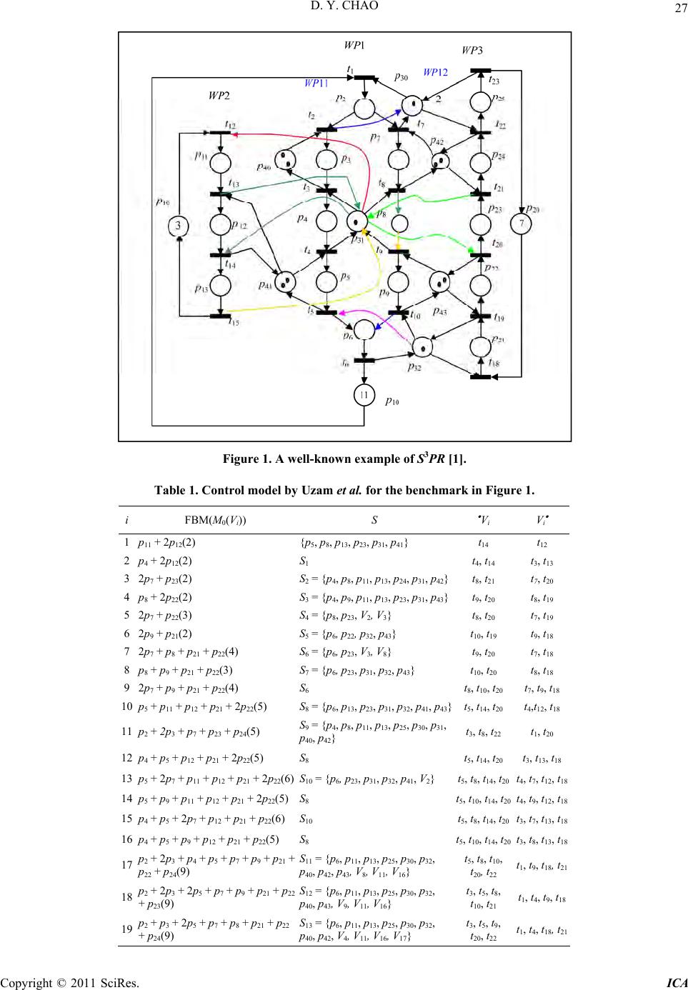 D. Y. CHAO Copyright © 2011 SciRes. ICA 27 Figure 1. A well-known example of S3PR [1]. Table 1. Control model by Uzam et al. for the benchmark in Figur e 1. i FBM(M0(Vi)) S Vi V i 1 p11 + 2p12(2) {p5, p8, p13, p23, p31, p41} t 14 t12 2 p4 + 2p12(2) S 1 t4, t14 t 3, t13 3 2p7 + p23(2) S 2 = {p4, p8, p11, p13, p24, p31, p42}t8, t21 t 7, t20 4 p8 + 2p22(2) S 3 = {p4, p9, p11, p13, p23, p31, p43}t9, t20 t 8, t19 5 2p7 + p22(3) S 4 = {p8, p23, V2, V3} t8, t20 t 7, t19 6 2p9 + p21(2) S 5 = {p6, p22, p32, p43} t10, t19 t 9, t18 7 2p7 + p8 + p21 + p22(4) S 6 = {p6, p23, V3, V8} t 9, t20 t 7, t18 8 p8 + p9 + p21 + p22(3) S 7 = {p6, p23, p31, p32, p43} t 10, t20 t 8, t18 9 2p7 + p9 + p21 + p22(4) S 6 t 8, t10, t20 t7, t9, t18 10 p5 + p11 + p12 + p21 + 2p22(5) S 8 = {p6, p13, p23, p31, p32, p41, p43}t5, t14, t20 t4,t12, t18 11 p2 + 2p3 + p7 + p23 + p24(5) S9 = {p4, p8, p11, p13, p25, p30, p31, p40, p42} t3, t8, t22 t 1, t20 12 p4 + p5 + p12 + p21 + 2p22(5) S 8 t 5, t14, t20 t3, t13, t18 13 p5 + 2p7 + p11 + p12 + p21 + 2p22(6) S10 = {p6, p23, p31, p32, p41, V2} t 5, t8, t14, t20 t4, t7, t12, t18 14 p5 + p9 + p11 + p12 + p21 + 2p22(5) S8 t5, t10, t14, t20 t4, t9, t12, t18 15 p4 + p5 + 2p7 + p12 + p21 + p22(6) S10 t 5, t8, t14, t20 t3, t7, t13, t18 16 p4 + p5 + p9 + p12 + p21 + p22(5) S 8 t5, t10, t14, t20 t3, t8, t13, t18 17 p2 + 2p3 + p4 + p5 + p7 + p9 + p21 + p22 + p24(9) S11 = {p6, p11, p13, p25, p30, p32, p40, p42, p43, V8, V11, V16} t5, t8, t10, t20, t22 t1, t9, t18, t21 18 p2 + 2p3 + 2p5 + p7 + p9 + p21 + p22 + p23(9) S12 = {p6, p11, p13, p25, p30, p32, p40, p43, V9, V11, V16} t3, t5, t8, t10, t21 t1, t4, t9, t18 19 p2 + p3 + 2p5 + p7 + p8 + p21 + p22 + p24(9) S13 = {p6, p11, p13, p25, p30, p32, p40, p42, V4, V11, V16, V17} t3, t5, t9, t20, t22 t1, t4, t18, t21  D. Y. CHAO Copyright © 2011 SciRes. ICA 28 4. Condition for State Loss To have lost live states, some live states must be forbid- den by the addition of Monitor VS. For states to be live, the α-siphon S must be always marked. For states to be forbidden, the total number of tokens in the complemen- tary set [S] of S must remain at its maximum, which cannot occur in the presence of ordinary VS. To turn M(S) > 0 (live) from M’(S) = 0 while maintaining M([S]) = M’([S]) = Mmax([S]) (forbidden), a token must be shifted from one place in [S] to another place in [S]. In the se- quel, we first deal with liveness of lost states followed by two different cases where state loss may or may not oc- cur. Lemma 2: Let S be a siphon and M0(S) > 0. M(S) > 0 [M R(N, M0)], if no transitions in S \ S ever fire. Proof: Only transitions in S \ S can fire to move to- kens from S into [S]. Transitions in S S fire to move tokens from S into S itself. Hence, the thesis holds. Observation 1: Let S be an α-siphon, VS’ S, (S \ S) VS’ . For the α-siphon S = S11 in Ta ble 1 , S S = {t1, t18}. If t1 and t18 never fire, tokens in S cannot leak out from S. There are 3 VS’ in S11: V8, V11 and V16. S S = {t1, t18} and t1 V11 , t18 V16 . Lemma 3: Let S be an α-siphon, VS’ S, M(VS’) = 0, M R(N, M0). Then no transitions in S \ S can ever fire. Proof: The thesis holds since all transitions in VS’ are disabled owing to th e fact that M(VS’) = 0 and (S \ S) VS’ by Observation 1. The abov e lemmas h elp prov e that mar king s, where an α-siphon is always marked, are live ones. Definition 6: Let S be an α-siphon, R C = { r| r PR, r R(cSi), cSi CS} the set of resource places whose holder places are also in that of control places of CS and = RC \ {rp}, where rp is an inter-place. p’ H(rp) is called a skew place. Theorem 1: Let S be an α-siphon, Ma(p) = 0, Ma(H(p) [S]) = M0(p), p CS, Ma R(N, M0). Then all transitions in S are dead. Proof: It is easy to see that Ma(S) = 0 and all transi- tions in S are dead. For the example, CS = {V11, V16}, R(V16) = {p31, p32, p41, p43}, RC = {p30, p31, p32, p40, p41, p42, p43}, rp = p31, and = Rc \ {rp} = {p30, p32, p40, p41, p42, p43}, where p30, p32, p40, p42, p43 are unmarked under FBM17. H(rp) = {p4, p8, p23} and each place in H(rp) is a skew place. Ma(p2) = Ma(H(p30) [S]) = M0(p30) = 1, Ma(p3) = Ma(H(p40) [S]) = M0(p40) = 2, M(p21) = Ma(H(p32) [S]) = M0(p32) = 1, and Ma(p7) + Ma(p24) = Ma(H(p42) [S]) = M0(p42) = 2, Ma(p9) + Ma(p22) = Ma(H(p43) [S]) = M0(p43) = 2. Note that Ma(p) = 0, p CS. Thus all output tran- sitions of p are dead . The rest transitions are outpu t tran- sitions of p6, p25, p4, p8, p23, which are also dead since Ma(p6) = Ma(p25) = Ma(p4) = Ma(p8) = Ma(p23) = 0. We first add Monitor V’, so that H(V’) = . This in- duces dead submarkings (markings restricted to opera- tion places or ) FBMa = p2 + 2p3 + p4 + p5 + p7 + p9 + p21 + p22 + p24, FBMb = p2 + 2p3 + 2p5 + p7 + p9 + p21 + p22 + p23 and FBMc = p2 + 2p3 + 2p5 + p7 + p8 + p21 + p22 + p24. Monitors V17, V18, and V 19 (called induced monitors) are added with M0(V17) = 9, M0(V18) = 9 and M0(V19) = 9, respectively. Now Monitor V’ is redundant since its controller re- gion ’ = {p2, p3, p5, p7, p9, p21, p22, p24} is a subset of that ( = {p2, p3, p4, p5, p7, p9, p21, p22, p24}) for Monitor V17 by the following lemma. Lemma 4 [11]: Let S be an SMS. 1 [S]. M, M1 R(N, M0) such that M( ) = M1( 1) = Mmax([S]), V and V1 are two monitors added such that M0(V) = M0(V1) = Mmax([S]) – 1 and [V] = , [V1] = 1. Then V1 is redun- dant. 1 and are the controller regions for Monitors V and V11, respectively. In the sequel, we will prove that when the above redundant monitor appears, there are lost states, and vice versa. Theorem 2: Let S be an α-siphon, the set of marked operation places when S is unmarked under Ma, and VS is the monitor added to S with M0(VS) = Mmax([S]) – 1 and H(VS) = . Let Mb(p) = Mb(r) = 1, Mb(p') = Ma(p') – 1, Mb(p*) = Ma(p*), p* P \ ({p, p'}, Mb R(N, M0), where p H(rp), rp an inter-place, r ( (p )) , p’ p H(r) and Ma was defined in Theorem 1. If H(r) [S] = {p’} and r S, then 1) Mb is a nonlive marking. 2) There are no lost live states iff Mb(p’) = 0 or M0(r) = 1 and a monitor has been added to prevent Mb from being reached. Proof: 1) Among all dead transitions under Ma, only output transitions of r may be enabled under Mb since Mb(r) = 1. If H(r) [S] = {p'}, the only possibly enab led transition is the output transition of both r and p. How- ever, after t fires, it reaches Ma, which is a dead marking. Thus, Mb is a nonlive marking. But t is disabled by VS since t is the output transition of VS and M(VS) = 0 (Mb([S]) = Ma([S]) + Mb(p) – Ma(p) + Mb(p') – Ma(p') = Ma([S]). 2) First assume a) Mb(p') > 0 (or M0(r) > 1). Let Mc R(N, M0) be such that Mc(p') = Mb(p') + 1 (i.e., adding a token to p'), Mc(p^) = Mb(p^) – 1 (to ensure Mb(V) = 0), Mc(p*) = Mb(p*), p* P \ ({p', p^}, where p^ H(r') H(V), p' H(V), V S, r' RC. Then M(H(r') S) = 1. By Lemma 2, S remains marked since V is unmarked to disable its output transi- tion in S \ S. All markings M’ where S and all other siphons in the final live controlled net are marked and  D. Y. CHAO Copyright © 2011 SciRes. ICA 29 M’(p) = Mc(p), p S [S]. Such states are live as proved below. Assume it necessarily evolves to a dead- lock state M*, then there exist an unmarked sip hon und er M*, which violates the fact that all siphons have been controlled. These states are lost since Mc() = Mb() = Mmax([VS]), which are not reachable by Monitor VS with M0(VS) = Mmax([S]) – 1. Next consider b) M b(p’) = 0 (or M 0(r) = 1). now does not include p'. One can no longer add a token to p' to induce M(H(r') S) = 1. Thus, there are no lost states. a) and b) together prove the thesis. For the example, p' = p5, r = p41 and H(r) [S] = {p'}. r has only one ou tput transition t4 with an input operation place in . The above theorem indicates that when M0(p41) = 1 (instead of 2 as in Figure 1), there will be no loss of good states. VS is not redundant and cannot be removed for the control. a) If M0(p41) > 1, then there will be lost live states by adding a token to p5 so that Mc(p5) = Mb(p5) + 1. These live states must be such that Mc() = Mmax(), which are not reachable by adding Monitor VS to make Mc() < Mmax(). To make Mc() = Mmax (), it must be that Mc(V) = Mb(V) = Ma(V) = 0, V = V16. This leads to Mc([V16]) = M0(V16) = 5 or Mc(p4) + Mc(p5) + Mc(p8) + Mc(p9) + Mc(p21) + Mc(p22) = M0(V16) = 5 Mc(p8) = 0, implies that α = Mc(p4) + Mc(p5) + Mc(p9) + Mc(p21) + Mc(p22) = 5. Note that the a ddition of Monitor V16 limits α to be no more than 5. However, setting α to 5 may not make S unmarked since some resource place (e.g., p43 or p32) in S may be marked (Mc(S) > 0) even though V16 is unmarked. These states Mc(S) > 0 will stay so (and are live as proved above) since transitions in S \ S are disabled by output control arcs from unmarked V16 and V11. Note that VS is redundant and can be removed. b) If M0(p41) = 1, then there will be no lost live states since Mc(p5) = 0 and the set c of marked operation places under Mc does not include p5. One can no longer add a token to c to make Mc(S) > 0. Hence, there are no lost states. Theorem 3: Let S be an α-siphon, the set of marked operation places when S is unmarked under Ma, and VS is the monitor added to S with M0(VS) = Mma x () – 1 and H(VS) = . Let Mb(p) = Mb(r) = 1, Mb(p*) = Ma(p*), p* P \ ({p, p'}, Mb R(N, M0), Mb(p’) = 0, where p H(rp), r ( (p )) , p’ p H(r). If r S and H(r) [S] {p'}, then 1) Mb is a nonlive marking, and 2) there are no lost live states by adding a monitor to pre- vent Mb from bei ng rea ched. Proof: 1) Similar to the proof of Theorem 2, the output transition of both r and p is an output transition of VS (Monitor for S) and disabled by unmarked VS. Other output transitions t' of r are also disabled as explained here. If H(r) [S] {p'}, then μ = \ {p'} ( = (H(r) [S]) {p}) is the complementary set of another siphon S’; the output transition set of VS' (control place for S') contains t'. Mb(p') = 0 implies that Mb(μ) = M0(rp) + M0(r) – 1 = M0(r) = Mb(p) + Mb(H(r) [S]) – Mb(p') = M0(S') – 1 = M0(VS’). Thus, VS' is unmarked to disable t' and all possible enab led transitions are dead and Mb is a nonlive marking, which needs a monitor V' with H(V') the set of unmarked operation places in [S]. 2) Note th at H(V') does not include p’ since Mb(p') = 0. Since Mb(μ \ {p}) + Mb(r) = M0(r), there is no way to add a token (to reach states forbidden by V') to enable some transition. Hence, such states are nonlive and there are no lost live states. For the example, there are two possible pairs of (r p p’): 1. (p43 p8 p9) and 2. (p42 p23 p24) for the above theo- rem. For Case 1, H(r) [S] = {p9, p22} {p' = p9}. For Case 2, H(r) [S] = {p7, p24} {p' = p24}. r has more than one output transition (1. t9, t19 and 2. t7, t21) with an input operation place in . 1 = (H(r) [S]) {p} = {p8, p9, p22}, μ1 = 1 \ {p'} = {p8, p22} = [S4], 2 = (H(r) [S]) {p} = {p7, p23, p24}, μ2 = 2 \ {p'} = {p7, p23} = [S3]. The corresponding submarkings are FBMb = p2 + 2p3 + 2p5 + p7 + p9 + p21 + p22 + p23 (Mb(p') = Mb(p24) = 0) and FBMc = p2 + 2p3 + 2p5 + p7 + p8 + p21 + p22 + p24(Mb(p') = Mb(p9) = 0),respectively. Thus, the set b of marked operation places under Mb does not include p'. One cannot add a token to a skew place inb to make Mc(S) > 0. Hence, there are no lost states. Combining Theorem s 2 and 3, we have Theorem 4: Let S be an α-siphon and all necessary monitors have been added such that there are no marked set ( S) of operation places with dead output tran- sitions. Then there are no lost live states iff Mb(p’) = 0 for all possible p' (defined in Theorem 3). Proof: Theorems 2 and 3 consider all cases where H(r) [S] = {p'} and H(r) [S] {p'}, respectively. Theo- rem 2 proves that there are no lost live states iff Mb(p') = 0 for all possible p'. Theorem 3 proves that if Mb(p') = 0, then Mb is a nonliv e marking and there are no lost states. Similar to the proof for Theorem 2, one can show that if there are no lost states, then it must be that Mb(p') = 0. All cases have been considered and the thesis is proved. In summary, this section develops the condition for a mixture siphon S to be involved in reaching fewer live states. After adding a monitor VS to S, new unmarked siphons may be generated. One new set of unmarked operation places may cover H(VS) of VS, as a proper sub- set. This makes VS redundant and some live states lost. The physics of loss of live states is as follows. Adding a token to a skew place (e.g., p4 in Figure 1) of S reduces  D. Y. CHAO Copyright © 2011 SciRes. ICA 30 a token in the holder set (e.g., p21 in Figure 1) of a re- source place r (e.g., p32 in Figure 1) in S, which in turn induces a token in r, thus making S marked. Such a state is live and forbidden since the total number of tokens in remains unchanged. 5. Conclusions This paper enhances an earlier paper (which estimates the number of lost states without reachability analysis) and develops theory to identify the siphon responsible for lost states for a well-known benchmark and explores the condition to achieve optimal controller without WC. If the condition is not met, one can apply the technique by Piroddi et al. to synthesize optimal controllers with WC. Future work should be addressed to synthesize suboptimal controller without WC when the condition cannot be satisfied. 6. References [1] J. Ezpeleta, J. M. Colom and J. Martinez, “A Petri Net Based Deadlock Prevention Policy for Flexible Manu- facturing Systems,” IEEE Transactions on Robotics and Automation, Vol. 11, No. 2, 1995, pp. 173-184. doi: 10.1109/70.370500 [2] Z. W. Li, J. Zhang and M. Zhao, “Liveness-Enforcing Supervisor Design for a Class of Generalized Petri Net Models of Flexible Manufacturing Systems,” IEE Pro- ceedings Control Theory & Applications, Vol. 1, No. 4, 2007, pp. 955-967. doi:10.1049/iet-cta:20060218 [3] C.-F. Zhong and Z.-W. Li, “Design of Liveness-Enforcing Supervisors via Transforming Plant Petri Net Models of FMS,” Asian Journal of Control (Special Issue on the Control of Discrete Event Systems), Vol. 6, No. 2, 2010, pp. 270-280. [4] J. W. Guo and Z. W. Li, “A Deadlock Prevention Ap- proach for a Class of Timed Petri Nets Using Elementary Siphons,” Asian Journal of Control, Vol. 12, No. 3, 2010, pp. 347-363. doi:10.1002/asjc.189 [5] M. Uzam and M. C. Zhou, “An Iterative Synthesis Ap- proach to Petri Net Based Deadlock Prevention Policy for Flexible Manufacturing Systems,” IEEE Transactions on Systems, Man, and Cybernetics A, Vol. 37, No. 3, 2007, pp. 362-371. doi:10.1109/TSMCA.2007.893484 [6] L. Piroddi, R. Cordone and I. Fumagalli, “Selective Si- phon Control for Deadlock Prevention in Petri Nets,” IEEE Transactions on Systems, Man, and Cybernetics A, Vol. 38, No. 6, 2008, pp. 1337-1348. doi:10.1109/TSM CA.2008.2003535 [7] L. Piroddi, R. Cordone and I. Fumagalli, “Combined Siphon and Marking Generation for Deadlock Prevention in Petri Nets,” IEEE Transactions on Systems, Man, and Cybernetics A, Vol. 39, No. 3, 2009, pp. 650-661. doi:10.1109/TSMCA.2009.2013189 [8] M. Uzam, Z. W. Li and M. C. Zhou, “Identification and Elimination of Redundant Control Places in Petri Net Based Liveness Enforcing Supervisors of FMS,” Interna- tional Journal of Advanced Manufacturing Technology, Vol. 35, No. 1-2, 2007, pp. 150-168. doi:10.1007/s00170- 006-0701-5 [9] D. Y. Chao, “Improvement of Suboptimal Siphon- and FBM-Based Control Model of a Well-Known S3PR,” IEEE Transactions on Automation Science and Engi- neering, Vol. 8, 2011. [10] Y.-Y. Shih and D. Chao, “Sequence of Control in S3PMR,” Computer Journal, Vol. 53, No. 10, 2010, pp. 1691-1703. doi:10.1093/comjnl/bxp081 [11] D. Chao and G. J. Liu, “A Simple Suboptimal Siphon- Based Control Model of a Well-Known S3PR,” Asian Journal of Control, December 2010. http://onlinelibrary. wiley.com/doi/10.1002/asjc.292/full [12] D. Y. Chao, “Computation of Elementary Siphons in Petri Nets for Deadlock Control,” Computer Journal, Vol. 49, No. 4, 2006, pp. 470-479. doi:10.1093/comjnl/bxl019 [13] D. Y. Chao, “A Graphic-Algebraic Computation of Ele- mentary Siphons of BS3PR,” Journal of Information Sci- ence and Engineering, Vol. 23, No. 6, 2007, pp. 1817-1831. [14] D. Y. Chao, “Incremental Approach to Computation of Elementary Siphons for Arbitrary S3PR,” IEE Proceed- ings Control Theory & Applications, Vol. 2, No. 2, 2007, pp. 168-179. |