Journal of Electromagnetic Analysis and Applications
Vol. 3 No. 11 (2011) , Article ID: 8337 , 6 pages DOI:10.4236/jemaa.2011.311072
Aspect Ratio: A Major Controlling Factor of Radiation Characteristics of Microstrip Antenna
![]()
Department of ECE, Siliguri Institute of Technology, Siliguri, Darjeeling, India.
Email: piyalirekha@yahoo.com
Received August 20th, 2011; revised September 17th, 2011; accepted October 3rd, 2011.
Keywords: Aspect Ratio, Co-Polarized Gain, Cross Polarized Radiation, Microstrip Patch
ABSTRACT
The effect of aspect ratio (width-to-length ratio) on overall radiation characteristics of a rectangular microstrip patch antenna is theoretically investigated with a view to develop a concrete physical insight in to the phenomenon. The detailed variation of co polarized and cross polarized radiation performance as a function of aspect ratio is thoroughly presented. The gain enhancement of a microstrip patch antenna along with a radical variation of cross polarized field radiation with aspect ratio is obtained. Indeed the conjecture of occurring different fringing fields with different aspect ratio is employed to theoretically estimate the effective size of a rectangular patch, and hence to determine the quantitative change in the gain value. Close agreement amongst the theory and simulations justifies the conjecture indicating a concrete physical insight in to the fact. The aspect ratio for which the cross polarized field radiation is minimum for a particular patch is also presented and justified quantitatively.
1. Introduction
A rectangular microstrip patch resonating with the fundamental TM10 mode radiates along the broad side and the field is linearly polarized. However, some degree of orthogonally polarized, called cross polarized radiations take place. Theoretical investigations were reported in [1, 2]. The cross polarized radiation becomes significantly prominent for probe-fed designs and particularly when the thickness and dielectric constant of the substrate increase [3,4]. The radiation characteristics of nearly square microstrip antenna are greatly affected by the shape and size of the ground plane [5].
Variable width-to-length ratio (aspect ratio p = a/b in Figure 1) severely affects the co polarized gain and cross polarization characteristics of microstrip patch antenna. Some recently reported articles [6,7] show the variation of input characteristics like operating frequency and input impedance of microstrip antenna as a function of aspect ratio. But no systematic study addressing the effect of aspect ratio (a/b) on radiation characteristics has been reported earlier. In order to alleviate the lacunae of the previous studies, we have investigated the effect of aspect ratio (a/b) on the overall radiation performance of microstrip antenna. The complete variation of co polarized gain along with cross polarization characteristics as a function of aspect ratio p has been presented thoroughly. The physical insight into the observed phenomena are indicated using simulation results. A quick hand calculation for estimation of change in co polarized gain as a function of aspect ratio along with the value of that (p) for which minimum cross polarized radiation occurs are also presented physically and quantitatively.
2. Antenna Geometry
A rectangular microstrip antenna with length b and width a is shown in Figure 1 (top-view of the patch and side view of whole antenna structure). A dielectric substrate of thickness h and relative permittivity of εr = 2.33 is sandwiched between the patch and ground plane. When this antenna is fed with coaxial probe at proper feed location (x', y'), the structure becomes radiating and the effective dimensions of length and width becomes b + 2∆b and a + 2∆a respectively as indicated in the figure. The ground plane dimension for the present investigation has been chosen to 0.5λ × 0.5λ.
3. Results and Discussions
Simulated results obtained for a wide range of aspect ratios which show the complete behavior of co polarized and cross polarized radiation fields. The investigation has
 (a)
(a)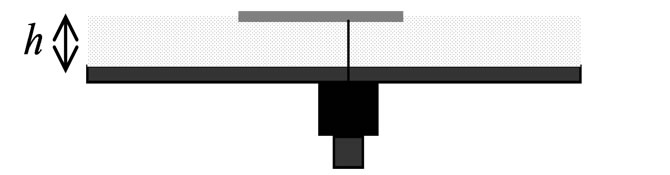 (b)
(b)
Figure 1. Schematic diagram of a rectangular patch (a) topview of the patch and (b) side view of whole antenna structure.
been done for a wide range of aspect ratios (p = a/b) from p = 1 to p = 2 with a patch having fixed length b = 30 mm, substrate thickness h = 1.575 mm and dielectric substrate of εr = 2.33. The feed position of the patch is kept unaltered for all values of aspect ratio at (x', y' = 1.9 mm, 0 mm). The results are organized in a systematic way and they are presented in the following sections. The antenna is resonant around 3 GHz.
3.1. Behavior of Co-Polarized Radiation as a Function of Aspect
3.1.1. Physical View
In Figure 2, the radiation characteristics of a conventional rectangular microstrip patch antenna without airgap and variable aspect ratio are shown. For a fixed length patch (b = 30 mm), increasing value of a causes increase in aspect ratio p. When p ratio increases from 1.0 to 1.7, the peak gain is found to increase by around 1.2 dB (Figure 2).
The identical observation is revealed in co polarized peak gain values when 1 mm air-gap has been introduced between the substrate and the ground plane though not shown in this paper.
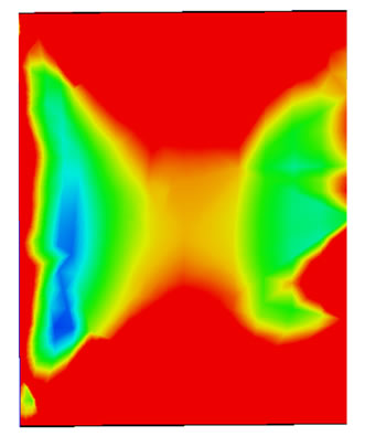
The physical insight in to obtaining such increment in peak gain with increased aspect ratio has been explored employing simulated current distribution on the patch surface, as shown in Figure 3. From a comparison of electric surface currents depicted in Figure 3, it is apparent that the current due to p = 1.5 is more uniformlydistributed over the central part of the patch than that due to p = 1.0. Also, the effective radiating area in Figure 3(b) is larger than that in Figure 3(a), which corroborates the improved gain of the patch.
The profile of the peak gain as a function of aspect ratio are shown in Figure 4 for the patch without air-gap. It is observed that the gain increases with the patch width up to a certain value of p = 1.5 and then it has a propensity to saturate as is clear from the figure.
3.1.2. Quantitative Estimation of Co-Polarized Gain Enhancement with Aspect Ratio
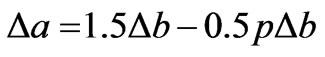
The gain of any antenna is directly related with its effective radiating area Aeff.. So without going to rigorous calculations of the fields and power for absolute gain values, we can simply compare the change in the gain value compared to an identical reference one (antenna with p = 1) as:
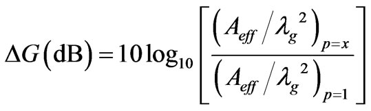 (1)
(1)
where x may be any value between 1 to 2.
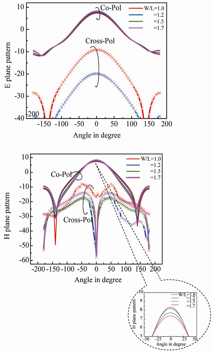
Figure 2. Radiation patterns for rectangular microstrip patch with different aspect ratio. (a) E plane; (b) H plane. Parameters: b =30 mm, h =1.575 mm, εr = 2.33.
 (a)
(a) (b)
(b)
Figure 3. Surface current distribution on the patch for (a) p = 1.0, (b) (c) p = 1.5. Parameters as in Figure 2 (scale for both: 0 - 4 A/m).
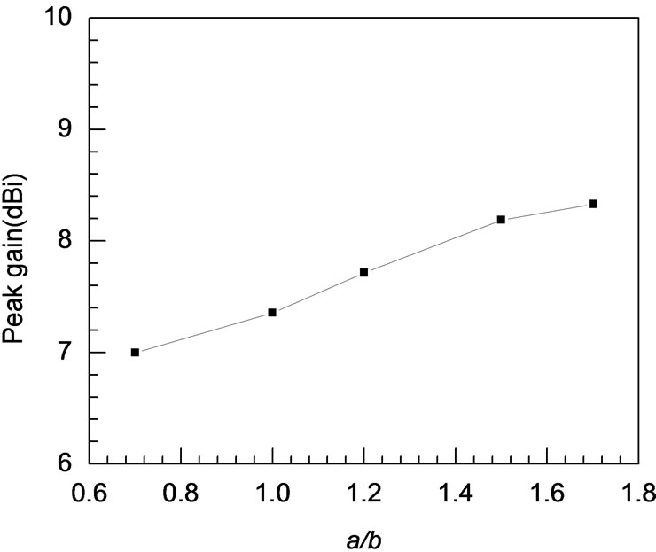
Figure 4. Variation of peak gain with aspect ratio for a rectangular patch. Parameters as in Figure 2.
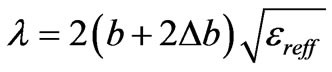
 (2)
(2)
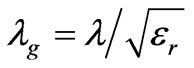
The operating wavelength λ can be theoretically determined as [6]
 (3)
(3)
where l is the operating wavelength of the signal. For a rectangular patch, as shown in Figure 1, its effective radiating area may be calculated as
 (4)
(4)
where, b and a are the physical length and width of the patch, respectively. The quantities Db and Da represent the effective increments in respective dimensions caused by the fringing electric fields, which can be accurately determined using the recent formulations developed by the present authors in [7] as
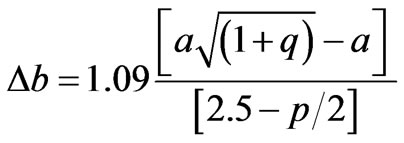 (5)
(5)
 (6)
(6)
Here, q is the fringing factor and its derivation is indicated in [6].
Using (1)-(5), the gain enhancement (∆G) of any rectangular microstrip antenna (RMA) with an aspect ratio p = x with respect to the reference antenna (p = 1) can be computed. The computed results of ∆G of RMA with some commonly used aspect ratio (i.e. p = 1.2, 1.5, 1.7) compared to reference antenna is shown in Table 1. The simulated results are also shown in the table to validate the theory and close mutual agreement is revealed between the theoretical prediction and simulated results.
3.2. Behavior of Cross Polarized Radiation as a Function of Aspect
3.2.1. Physical View
The cross polarized radiation field is found to be affected severely with aspect ratio p. This cross polarized radiation is generally small in E plane whereas this in H plane degrades the overall radiation performance strictly, as obtained in the open literature [9]. The fact is very clear from Figure 2. Moreover, the cross-polarized radiation in H plane becomes maximum around 50˚ of the broadside direction and this is equally valid for all values of aspect ratio p from 1 to 2 as depicted in Figure 2. But the maximum value of the cross polarized radiation field varies with aspect ratio p and this value becomes minimum for p =1.37 as shown in Figure 5.
Thus Figure 5 is indicative in terms of revealing opti-
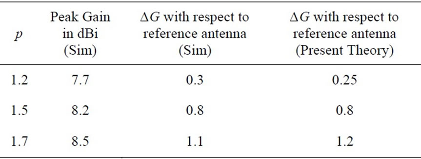
Table 1. Comparison of simulated and computed results of gain enhancement with respect to reference antenna (p = 1) Peak Gain of Reference Antenna (p = 1) = 7.4 dB.
mum p = 1.37 for obtaining optimum gain along with minimum cross polarized radiation. With a view to develop a complete physical idea, the automatic excitation of higher order modes for different aspect ratios are presented in Figure 6. Here, all the patches were fed at optimum matched location and it is seen that a patch with aspect ratio 1.37 is almost free from unwanted excitation of the higher order modes as observed from the figure. As we know that the cross polarized radiation fields are mostly due to the orthogonal higher order modes, Figure 6 corroborate the reality of getting minimum cross polarized radiation with a microstrip patch having a/b = 1.37.
3.2.2. Quantitative Estimation
The cross polarized radiation fields are mainly due to the radiation of orthogonal higher order modes and these radiation takes place from non-radiating slots of RMA which are separated by the width of the patch a. These two non radiating slots can be considered to form a 2 element array which are responsible for such cross po-
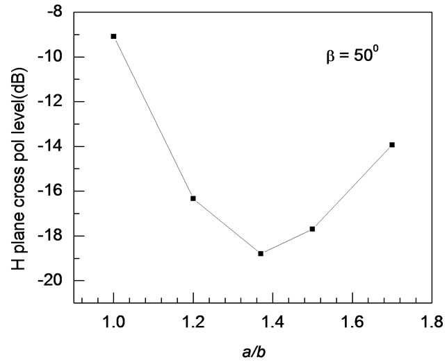
Figure 5. Variation of maximum cross polarized radiation level at 50˚ of broadside direction (β = 50˚) as function of aspect ratio for a rectangular patch. Parameters as in Figure 2.
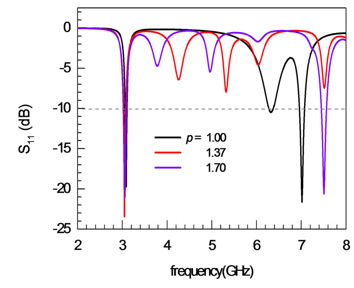
Figure 6. Return loss characteristics as a function of frequency for different aspect ratios (all are fed at matched point). Parameters as in Figure 2.
larized radiation.
Thus the array factor (Af) becomes
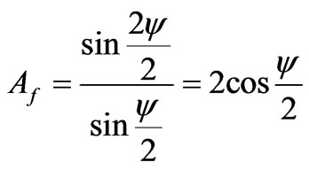 (7)
(7)
here ψ is the phase shift between the radiations coming from adjacent radiators and
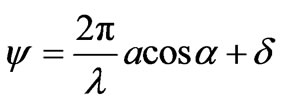 (8)
(8)
where α is the angle between the array axis and the point where we are interested to find the array factor Af.
Now the array factor Af of two non radiating slots along with primary radiation from those slots produces maximum at certain angle β of the broadside direction. Thus we are concerned with the array factor at that angle where α = (90˚ – β). δ is the phase shift between two non radiating slots and this depends on the distance between them i.e. the width a of the patch.
Hence,
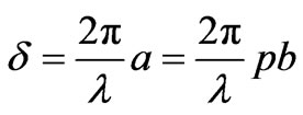
 (9)
(9)
Thus 
 (10)
(10)
 (11)
(11)
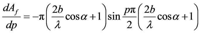 (12)
(12)
The left hand side of the Equation (12) become zero if,
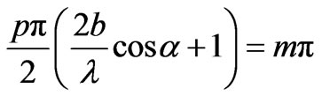
where m = 0, 1, ···
 (13)
(13)
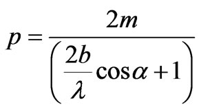
Thus  or
or
Now,
and this becomes positive if
 (14)
(14)
Thus the minimum value of p is as given by Equation (14).
For the present investigation, we are concerned to find the array factor at β = 50˚ as is clear from Figure 2. Hence α = 40˚. Using b = 30 mm, λ = 100 mm for resonant frequency fr = 3 GHz Equation (14) gives p = 1.37 which is in excellent agreement with the simulation result as depicted in Figure 5.
Again for the patch described in [10], it is found that cross polarized radiation becomes dominant at β = 36˚ which is equally valid for two aspect ratios p =1.25 and 1.5 as shown in of Figure 3 [10]. Thus α = 54˚ for two patches (with b = 22.58 mm, λ = 78.94 mm for resonant frequency fr = 3.8 GHz )investigated in [10]. The use of Equation (14) gives that the minimum cross polarized radiation occurs when p = 1.49 which is similar with the experimental results reported in [10]. Hence the aspect ratio p for which the cross polarized radiation becomes minimum is strictly dependent on the patch length b, operating wavelength λ and the angle β at which cross polarized radiation becomes maximum.
4. Co-Polarized to Cross Polarized Radiation Ratio
For the dominant TM10 mode excitation and linear polarization, the mode TM02 contributes maximum to the cross polarization as obtained from [9]. Following the theory developed in [10] and introducing the new effective dimensions of the patch, the co polarized to cross polarized field radiation ratio r in dB scale is given as:
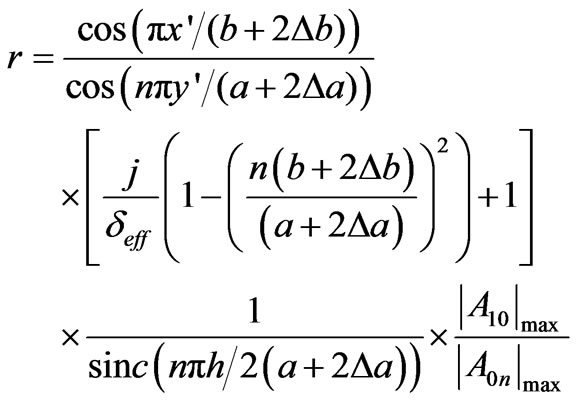 (15)
(15)
where δeff is effective loss tangent = 0.001.
And A10 and A0n are excitation amplitudes and can be determined from [11] introducing new effective dimensions of the patch as
 (16)
(16)
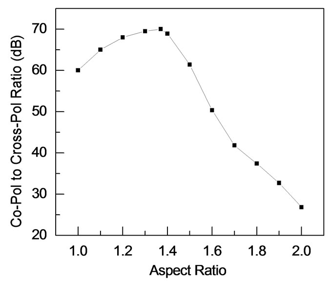
Figure 7. Variation of co polarized to cross polarized radiation ratio as a function of aspect ratio for a rectangular patch. Parameters as in Figure 2.
C is constant and  as given in [11]
 (17)
(17)
 (18)
(18)
 (19)
(19)
And Gmn is obtained from [11].
This ratio r is plotted as function of aspect ratio p in Figure 7 and it is found that the ratio is small when p =1 and then increases and becomes maximum at p = 1.37. Then as p increases r decreases. Simulation results depicted in Figures 4 and 5 further corroborates that the ratio becomes maximum at p = 1.37.
5. Conclusions
The effects of the width to length ratio (aspect ratio) of a RMA on its overall radiation characteristics have been investigated thoroughly. It shows the complete variation of co polarized gain and cross polarized field radiation as a major function of aspect ratio. Some optimum value of a/b is presented which should provide optimum gain, minimum cross-polarization radiation performance. The results obtained are justified qualitatively as well as quantitatively.
REFERENCES
- K. F. Lee, K. M. Luk and P. Y. Tam, “Cross-Polarization Characteristics of Circular Patch Antennas,” Electronic Letters, Vol. 28, No. 6, 1992, pp. 587-589. doi:10.1049/el:19920370
- T. Huynh, K. F. Lee and R. Q. Lee, “Cross-Polarization Characteristics of Rectangular Patch Antennas,” Electronic Letters, Vol. 24, No. 8, 1988, pp. 463-464. doi:10.1049/el:19880313
- A. A. Kishk and L. Shafai, “The Effects of Various Parameters of Circular Microstrip Antennas on Their Radiation Efficiency and the Mode Excitation,” IEEE Transactions on Antennas and Propagation, Vol. 34, No. 8, 1986, pp. 969-976. doi:10.1109/TAP.1986.1143939
- A. Petosa, A. Ittipiboon and N. gagnon, “Suppression of Unwanted Probe Radiation in Wide Band Probe-Fed Microstrip Patches,” Electronic Letters, Vol. 35, No. 5, 1999, pp. 355-357. doi:10.1049/el:19990269
- C.-W. Su and K.-L. Wong, “Circularly Polarized Microstrip Antenna with a Rectangular Ground Plane,” Microwave and Optical Technology Letters, Vol. 37, No. 2, 2003, pp. 93-95. doi:10.1002/mop.10833
- S. Chattopadhyay, M. Biswas, J. Y. Siddiqui and D. Guha, “Rectangular Microstrips with Variable Air-Gap Varying Aspect Ratio: Improved Formulation and Experiments,” Microwave Optical Technology Letters, Vol. 51, No. 1, 2009, pp. 169-173.
- S. Chattopadhyay, M. Biswas, J. Y. Siddiqui and D. Guha, “Input Impedance of Probe-Fed Rectangular Microstrip Antennas with Variable Air-Gap and Varying Aspect Ratio,” IET Microwaves, Antennas and Propagation, Vol. 3, No. 8, 2009, pp. 1151-1156. doi:10.1049/iet-map.2008.0320
- HFSS, “High Frequency Structure Simulator, Version 11.1,” Ansoft Corp, Pittsburgh, 2008.
- R. Garg, P. Bhartia, I. Bahl and A. Ittipiboon, “Microstrip Antenna Design Handbook,” Artech House, Norwood, 2001.
- M. L. Oberhart, Y. T. Lo and R. Q. H. Lee, “New Simple Feed Network for an Array Module of Four Microstrip Elements,” Electronics Letters, Vol. 23, No. 9, 1987, pp. 436-437. doi:10.1049/el:19870314
- K. R. Carver and J. W. Mink, “Microstrip Antenna Technology,” IEEE Transactions on Antennas and Propagation, Vol. 29, No. 1, 1981, pp. 2-24. doi:10.1109/TAP.1981.1142523
- W. F. Richards, Y. T. Lo and D. D. Harrison, “An Improved Theory for Microstrip Antennas and Applications,” IEEE Transactions on Antennas and Propagation, Vol. 29, No. 1, 198, pp. 38-461. doi:10.1109/TAP.1981.1142524
- N. Herscovici, “New Considerations in Design of Microstrip Antennas,” IEEE Transactions on Antennas and Propagation, Vol. 46, No. 6, 1998, pp. 807-812. doi:10.1109/8.686766