Journal of Electromagnetic Analysis and Applications
Vol. 2 No. 1 (2010) , Article ID: 1225 , 6 pages DOI:10.4236/jemaa.2010.21004
Research on Torque-Angle Characteristic of Large Gap Magnetic Drive System
![]()
College of Mechanical and Electrical Engineering, Central South University, Changsha, China.
Email: x_y616@163.com
Received August 18th, 2009; revised September 20th, 2009; accepted September 28th, 2009.
Keywords: Magnetic Drive, Large Gap, Torque-Angle Characteristic, Permanent Magnetic Gear (Permanent Magnet)
ABSTRACT
The principle and design method of the large gap magnetic drive system is studied in this work. The calculation model of the torque-angle characteristic in the large gap magnetic drive system driven by traveling wave magnetic field is established. The calculation model is computed by using MATLAB software, and the pattern of the system’s torque-angle characteristic is obtained by analyzing study results. These results indicate that: torque-angle characteristic and the driving torque of the system can be adjusted by changing the electric current of coil, the magnetization of permanent magnetic gear, the inner diameter of permanent magnetic gear, the coupling distance between electromagnet and permanent magnetic gear, the outer diameter of permanent magnetic gear, and the axial length of permanent magnetic gear.
1. Introduction
Magnetic drive technology is used to realize a non-contact transmission of forces and moments by using magnetic force produced by permanent magnetic material or electro-magnetic mechanism. It has become a study hotspot in the field of mechanical drive [1].
Pan Zheng and Yousef Haik [2] presented two models of a magnetically driven screw pumps that were developed for blood pump designing. The magnetic characteristics for the coupling force and torque were investigated. The power was transmitted to the pump from an outside motor through magnetic coupling without physical connection.
Karel F [3] used the rotary field to drive fluid in the square vessel, and established the magnetic force computation model of system.
ZHAO Han [4] established and simulated the physics mathematical model and the dynamic property model of the rare earth permanent magnetic gear drive system. The torque calculation formula of system was derived.
Michael Schreiner [5] made a permanent magnet be levitated. A mathematical model for the described effect was presented.
On the characteristic of the non-bearing magnetic resistance motor, MASATSUGU TAKEMOTO [6] established the torque computation equation of the rotor.
Kwang Suk Jung and Yoon Su Baek [7] made a mover be levitated by magnetic force between iron-core electromagnets attached under the upper-side of a stator and ferromagnetic plates belonging to the mover.
Nowadays, in the application of magnetic drive technology, the gap between the system magnetic poles is small. But when the gap between active and passive magnetic pole increases, the driving force cannot ensure the system reliability. Currently, literatures about application of magnetic drive technology on the axial flow type blood pump driving are few. In order to enhance the reliability of magnetic drive system with a large gap, a certain magnetic drive system driven by traveling wave magnetic field whose air gap reaches 60mm is studied [8]. In this paper, the torque-angle characteristic of the system is studied, and a theoretical basis for the design of the large gap magnetic drive system can be deduced from the study result.
2. Structure of the Large Gap Magnetic A.Drive System
2.1 Principle of the Passive Permanent Magnet’s Rotation
The principle of rotation of the passive permanent magnet is shown in Figure 1. Working state of the system depends on the magnetic force which is produced by
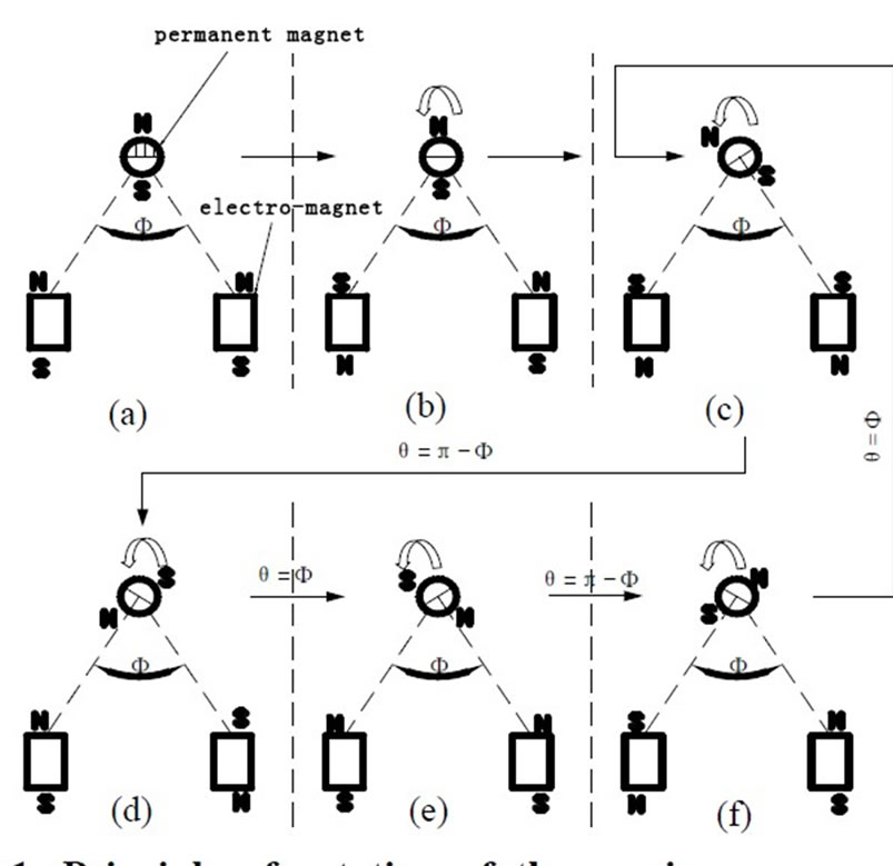
Figure 1. Principle of rotation of the passive permanent magnet
permanent magnet and the electromagnet. In Figure 1(a), the electromagnet produces N pole on both sides of the permanent magnet called the state NN. It also adjusts the top pole of the permanent magnet to N, the bottom pole to S. In Figure 1(b), the electromagnet produces the state SN and makes the permanent magnet to rotate anticlockwise. In Figure 1(c) to Figure 1(f), when the permanent magnet rotates for one cycle, the electromagnet completes the state variation of SS→NS→NN→SN. We can adjust the permanent magnet’s speed by modifying the electromagnet’s magnetic poles state switching frequency; furthermore by modifying the timing of the electromagnet’s magnetic poles state switching we can obtain a clockwise rotation of the permanent magnet.
Therefore, the designing of a large gap magnetic drive system can be realized according to the transmission principle mentioned above.
2.2 Design of the Large Gap Magnetic Drive System
As shown in Figure 2, the iron core is circled by 4 groups of coils. These coils output pulse through the MCU as shown in Figure 3. P1.0 causes coil #1 to produce N pole on the left side of the permanent magnet, P1.1 causes coil #2 to produce S pole on the left side of the permanent magnet, P1.2 causes coil #3 to produce S pole on the right side of the permanent magnet, and P1.3 causes coil #4 to produce N pole on the right side of the permanent magnet. So all kinds of electromagnet magnetic poles state as shown in Figure 1 can be realized and the permanent magnet can be driven by the control software.
The large gap magnetic drive system can be used to drive axial flow type blood pump. The pump is composed of bearings, impeller and permanent magnet, as shown in Figure 4 and Figure 5.
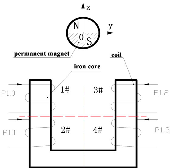
Figure 2. Structure of the large gap magnetic drive system
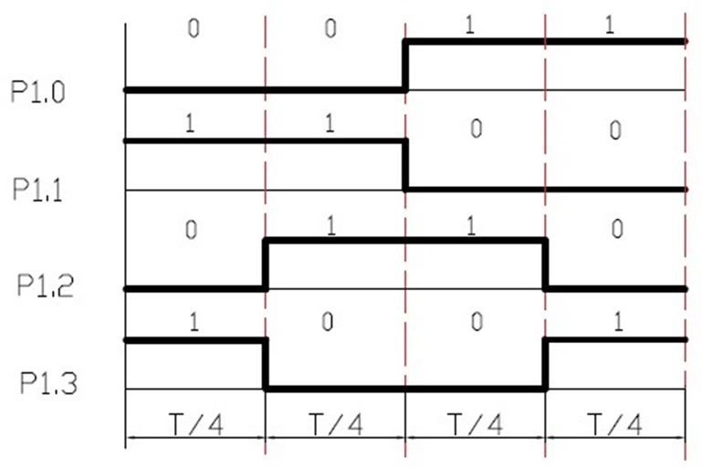
Figure 3. Output pulse succession of electromagnet’s coils
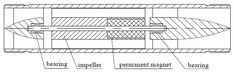
Figure 4. Schematic of an axial flow type blood pump
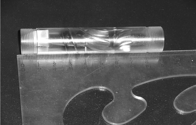
Figure 5. Prototype of an axial flow type blood pump
3. Establishment of Torque-Angle Characteristic’s Calculation Model of the System
3.1 Research Foundation
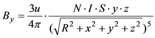
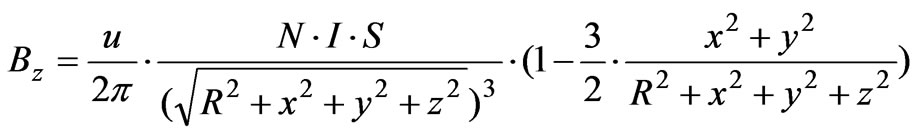
The mathematical model of the system’s spatial magnetic field can be obtained from [9]:
 (1)
(1)
 (2)
(2)
 (3)
(3)
In Formulas (1)-(3),  ,
,  ,
,  are the spatial magnetic field component in the
 ,
,  and
and  directions respectively. The coordinate system is shown in Figure 2.
  is the number of windings of coil,
  is the radius of coil.
  is the electric current of coil,
  is the area of coil, and
  is the magnetic conductivity in the 4 electromagnet magnetic poles states (NS, SS, SN and NN).
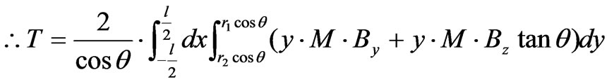
The mathematical model of the system’s driving torque can be obtained from [10]:
 (4)
(4)
In Formula (4),  ,
,  ,
,  ,
,  and
and  are the outer radius, the inner radius, the axial length, the corner, the magnetization of the permanent magnet respectively. Establishment of torque-angle characteristic’s calculation model of the system for example, the system’s electromagnet is Electromagnet C57 (In the coordinate system of Figure 2, the electromagnet is named by the iron coresize in the y direction. If the size along the y direction is 57mm, it is called Electromagnet C57). The distance in the z direction between electromagnet and the permanent magnet is 60mm.
According to Formula (4) and the principle of the passive permanent magnet’s rotation shown in Figure 3, the rotation process of the permanent magnet in one cycle can be divided into 4 stages. So the Formula (4) can be decomposed into 4 piecewise functions:
In the vicinity of the state NS of the system’s electromagnet magnetic poles, the permanent magnet’s corner range is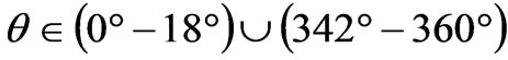 . In the vicinity of the state SS of the system’s electromagnet magnetic poles, the permanent magnet’s corner range is
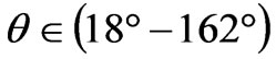 . In the vicinity of the state SN of the system’s electromagnet magnetic poles, the permanent magnet’s corner range is
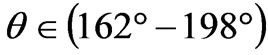 . In the vicinity of the state NN of the system’s electromagnet magnetic poles, the permanent magnet’s corner range is
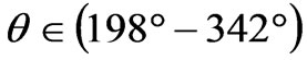 .
.
So the calculation model of the system’s torque-angle characteristic can be established as follows:
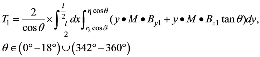 (5)
(5)
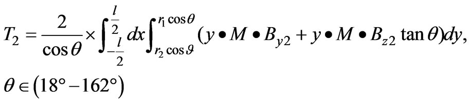 (6)
(6)
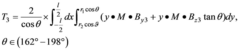 (7)
(7)
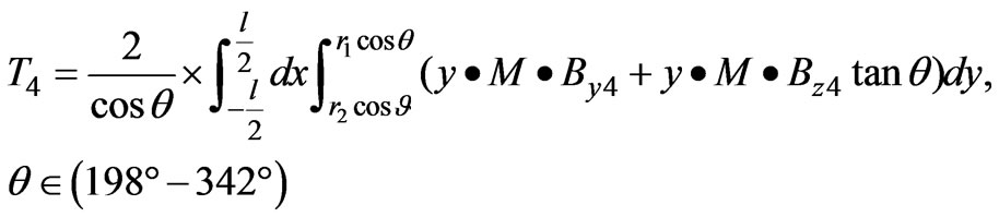 (8)
(8)
In Formulas (5)-(8), T1 is the system’s driving torque when electromagnet’s magnetic poles are in the state NS. T2 is the system’s driving torque when electromagnet’s magnetic poles are in the state SS. T3 is the system’s driving torque when electromagnet’s magnetic poles are in the state SN. T4 is the system’s driving torque when electromagnet’s magnetic poles are in the state NN. By1, Bz1 are the magnet field component in the y and z directions respectively when the electromagnet’s magnetic poles are in the state NS and can be obtained by Formulas (2) and (3).  are the magnet field component in the y and z directions respectively when the electromagnet’s magnetic poles are in the state SS and can be obtained by Formulas (2) and (3).
  are the magnet field component in the y and z directions respectively when the electromagnet’s magnetic poles are in the state SN and can be obtained by Formulas (2) and (3).
  are the magnet field component in the y and z directions respectively when the electromagnet’s magnetic poles are in the state NN and can be obtained by Formulas (2) and (3).
4. Computation of Torque-Angle Characteristic’s Calculation Model of the System
In view of the Formulas (5)-(8), the system’s driving torque under each kind of permanent magnet’s corner can be obtained using MATLAB software. So the calculation model of the system’s torque-angle characteristic was computed.
4.1 Basic Parameter Conditions of the System
Electromagnet C57; the number of windings of 4 coils is 400; the electric current of the coil is 1A; the outer diameter of the permanent magnet is 12mm; the inner diameter of the permanent magnet is 2mm; the magnetization of the permanent magnet is 900KA/m; the area of the coil is 33mm2; the axial length of the permanent magnet is 15mm; the distance in the z direction between the electromagnet and the permanent magnet is 60mm.
4.2 The Result of Computation
In Figures 6-11, the x-axis is the permanents corner (radian). The y-axis is the system’s driving torque (Nmm).
1) The electric current of the coil is changed to 0.9A, 1.2A, and 1.7A respectively. Other parameters of the basic conditions keep constant. The influence of the coil’s electric current on the system’s torque-angle characteristic is studied and shown in Figure 6.
2) The distance along the z direction between electromagnet and the permanent magnet is changed to 40mm, 50mm, 60mm and 65mm respectively. Other parameters of the basic conditions keep constant. The influence of the couple distance on the system’s torque-angle characteristic is studied and shown in Figure 7.
3) The magnetization of the permanent magnet is changed to 800 KA/m, 900 KA/m and 955 KA/m respectively. Other parameters of the basic conditions keep constant. The influence of the permanent magnet’s magnetization on the system’s torque-angle characteristic is studied and shown in Figure 8.
4) The inner diameter of the permanent magnet is changed to 2mm and 3mm respectively. Other parameters of the basic conditions keep constant. The influence of the inner diameter of the permanent magnet on the system’s torque-angle characteristic is studied and shown in Figure 9.
5) The outer diameter of the permanent magnet is changed to 12mm, 15mm and 8.2mm respectively. Other parameters of the basic conditions keep constant. The influence of the outer diameter of the permanent magnet on the system’s torque-angle characteristic is studied and shown in Figure 10.
6) The axial length of the permanent magnet is changed to 15mm, 25mm and 20mm respectively. Other parameters of the basic conditions keep constant. The influence of the axial length of the permanent magnet on
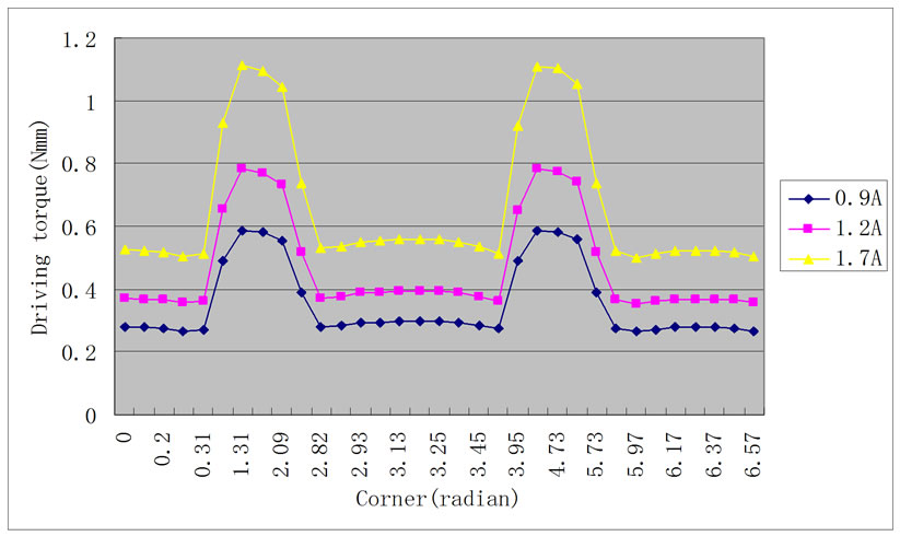
Figure 6. The influence of the coil’s electric current on the system’s torque-angle characteristic
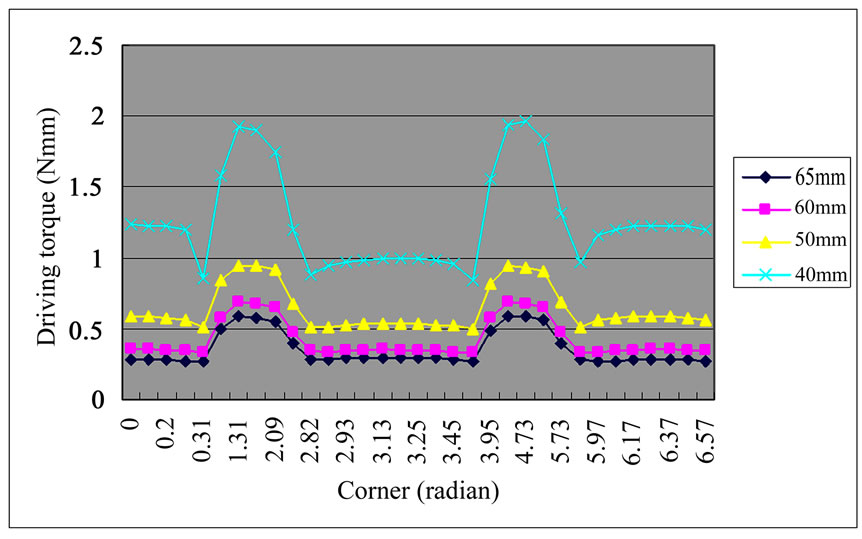
Figure 7. The influence of the couple distance on the system’s torque-angle characteristic
the system’s torque-angle characteristic is studied and shown in Figure 11.
4.3 Analysis
1) In the permanent magnet’s rotation cycle, the magnetic poles state of the electromagnet pass through NS→SS→ SN→NN, so the system’s torque-angle characteristic is periodic. When the permanent magnet’s corner is located in , the corresponding magnetic poles of the electromagnet are in the state NS. When the permanent magnet’s corner is located in
 ,
,
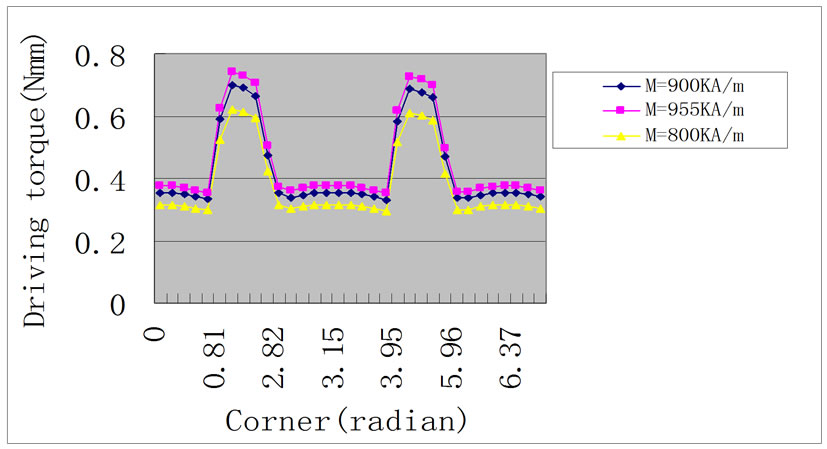
Figure 8. The influence of the permanent magnet’s magnetization on the system’s torque-angle characteristic
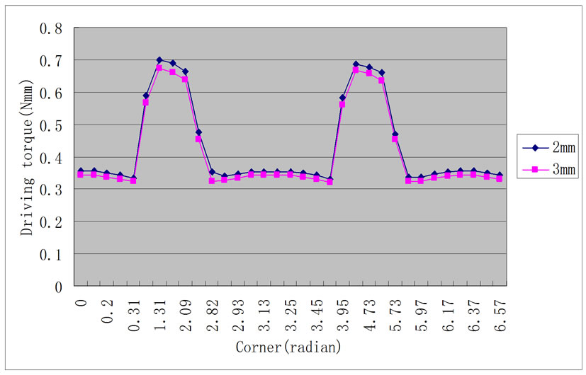
Figure 9. The influence of the inner diameter of the permanent magnet on the system’s torque-angle characteristic
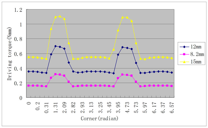
Figure 10. The influence of the outer diameter of the permanent magnet on the system’s torque-angle characteristic
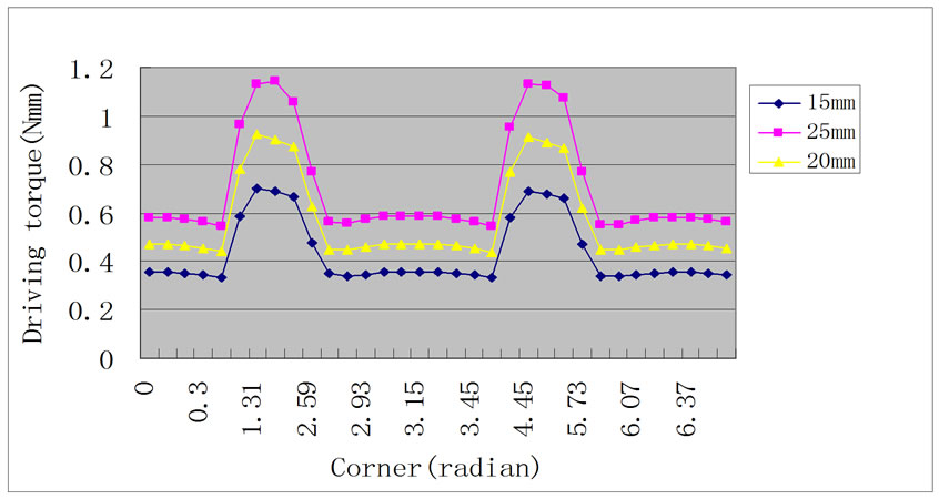
Figure 11. The influence of the axial length of the permanent magnet on the system’s torque-angle characteristic
the corresponding magnetic poles of the electromagnet are in the state SS. When the permanent magnet’s corner is located in , the corresponding magnetic poles of the electromagnet are in the state SN. When the permanent magnet’s corner is located in
 , the corresponding magnetic poles of the electromagnet are in the state NN.
2) In the vicinity of the 4 states of the electromagnet, because of the interaction between the permanent magnet and the electromagnet, the system’s driving torque present a maximum value. This maximum value’s position is determined by the relative spatial position between the permanent magnet and the electromagnet’s coil.
In the vicinity of the state NS, the system’s driving torque is symmetric about . It decreases in the interval
  and increases in the interval
 . The maximum value of the system’s driving torque appears about
  because the size and direction of the driving torque, which is acted on the permanent magnet by the electromagnet’s 2 magnetic poles, are the same.
In the vicinity of the state SS, the system’s driving torque is symmetric about . It decreases in the interval
  and increases in the interval
 . The maximum value of the system’s driving torque appears about
  because the size and direction of the driving torque, which is acted on the permanent magnet by the electromagnet’s 2 magnetic poles, are the same.
In the vicinity of the state SN, the system’s driving torque is symmetric about . It decreases in the interval
  and increases in the interval
 . The maximum value of the system’s driving torque appears about
  because the size and direction of the driving torque, which is acted on the permanent magnet by the electromagnet’s 2 magnetic poles, are the same.
In the vicinity of the state NN, the system’s driving torque is symmetric about . It decreases in the interval
  and increases in the interval
 . The maximum value of the system’s driving torque appears about
  because the size and direction of the driving torque, which is acted on the permanent magnet by the electromagnet’s 2 magnetic poles, are the same.
3) The magnetic pole state NN of the electromagnet is produced by coils #1 and #4, and SS is produced by #2 and #3 coil. In states NN and SS, the spatial magnetic field’s intensity is the same, directions are opposite, and the system’s driving torque is equal.
4) The magnetic pole state NS of the electromagnet is produced by coils #1 and #3, and SN is produced by coils #2 and #4. In states NS and SN, the spatial magnetic field’s directions are opposite. Because the distance from coils #2 and #4 to permanent magnet is bigger than the distance from coils #1 and #3 to permanent magnet, the spatial magnetic field’s intensity and the system’s driving torque are greater in the state NS than in the state SN.
5) Because the magnetic pole’s distance between the permanent magnet and the electromagnet are bigger in states NS and SN than in states SS and NN, the spatial magnetic field’s intensity and the system’s driving torque are lower in states NS and SN than in states SS and NN.
6) The system’s driving torque can be improved by increasing the electric current of the coil and the magnetization of permanent magnetic gear, decreasing the inner diameter of permanent magnetic gear and the coupling distance between the system’s magnet poles, and increasing the outer diameter of permanent magnetic gear and the axial length of permanent magnetic gear.
5. Conclusions
Through this paper, principle of the passive permanent magnet’s rotation is analyzed, and the design method of the large gap magnetic drive system is ascertained. Based on the spatial magnetic field and the driving torque’s mathematical model in the large gap magnetic drive system, the calculation model of the system’s torque-angle characteristic is established.
Using MATLAB software, the calculation model of the system’s torque-angle characteristic is computed and by analyzing the study results, the change pattern of the system’s torque-angle characteristic is obtained.
By this, we can know that the system’s driving torque can be adjusted by changing the electric current of the coil, the magnetization of permanent magnetic gear, the inner diameter of permanent magnetic gear, the coupling distance between system magnet pole, the outer diameter of permanent magnetic gear, and the axial length of permanent magnetic gear.
These study results provide a theoretical basis for designing the large gap magnetic drive system with stronger driving ability.
6. Acknowledgment
This work is supported by National High Technology Research and Development Program of China (No. 2006AA02Z4E8); the National Natural Science Foundation of China (No.50775223; No.50875266); the Research Fund for the Doctoral Program of Higher Education of China (No.20070533125); as well as the Research Fund of Changsha University (No.CDJJ-09010208).
REFERENCES
- X. D. Xu, Z. L. Gong, J. P. Tan, “Blood pump driven system based on extracorporeal magnetic filed couple,” Journal of Central South University (Science and Technology), Vol. 38, No. 8, pp. 711–714, 2007.
- P. Zheng and Y. Haik. “Force and torque characteristics for magnetically driven blood pump,” Journal of Magnetism and Magnetic Materials, Vol. 241, pp. 292– 302, 2002.
- F. Karel, “A numerical study of flows driven by a rotating magnetic field in a square container,” European Journal of Mechanics B/Fluids, No. 10, pp. 1–10, 2007.
- H. Zhao, Y. Wang, J. TIan, “Review of study on magnet machine and mechanism,” Chinese Journal of Mechanical Engineering, Vol. 39, No. 12, pp. 311–36, 2003.
- M. Schreiner, “The driving torque of a rotating levitated cylindrical permanent magnet above a superconductor,” Applied Mathematical Modelling, Vol. 31, No. 2, pp. 854–865, 2007.
- M. Takemoto, A. Chiba, H. Akagi, and T. Fukao, “Torque and suspension force in a bearingless switched reluctance motor,” Electrical Engineering, No. 2, pp. 72–82, 2006.
- K. S. Jung and Y. S. Baek, “Precision stage using a non-contact planar actuator based on magnetic suspension technology,” Mechatronics, Vol. 13, No. 4, pp. 981–999, 2003.
- J. P. Tan, Y. Xu, T. X. Li, and Y. L. Liu, “The scheme design and application of large gap magnetic drive system which is driven by traveling wave magnetic field,” IEEE International Conference on Measuring Technology and Mechatronics Automation (ICMTMA’09), Zhangjiajie, China, April 2009.
- L. P. Ren, J. S. Zhao “The distribution pattern of magnetic dipole’s spatial magnetic field,” Hydrographic Surveying and Charting, Vol. 22, No. 2, pp. 18–21, 2002.
- Y. Xu and J. P. Tan, “Calculation method of driving torque of the large gap magnetic drives system,” Journal of Hunan University (Natural Sciences), Vol. 36, No. 7, pp. 30–35, 2005.