Int'l J. of Communications, Network and System Sciences
Vol.4 No.1(2011), Article ID:3693,9 pages DOI:10.4236/ijcns.2011.41004
Cognitive Radio Sensor Node Empowered Mobile Phone for Explosive Trace Detection
1Department of Electronics & Communication Engineering, Netaji Subhash Engineering College, Kolkata, India
2Department of Information Technology, Institute of Engineering & Management, Kolkata, India
3DOEACC Society, Kolkata Centre, Kolkata, India
E-mail: moonlight72960@rediffmail.com, mohuyacb@yahoo.com, jchedrcc@yahoo.com
Received October 26, 2010; revised November 17, 2010; accepted November 19, 2010
Keywords: Cognitive Radio Sensor Node, Sensor Network, Explosive Vapor Sensor, Software-Defined Radio, Explosive Trace Detection, Mobile Phone
Abstract
Usefulness of sensor network applications in human life is increasing day by day and the concept of wireless connection promises new application areas. Sensor network can be very beneficial in saving human life from terrorist attacks causing explosion in certain areas leading to casualties. But realization of the sensor network application in explosive detection requires high scalability of the sensor network and fast transmission of the information through real time monitoring and control. In this paper a novel mechanism for explosive trace detection in any populated area by the use of mobile telephony has been described. The aim is to create a system that will assure common men, local population and above all the nation a secured environment, without disturbing their freedom of movement. It would further help the police in detection of explosives more quickly, isolation of suicide bombers, remediation of explosives manufacturing sites, and forensic and criminal investigation. To achieve this, the paper has projected an idea that can combine the strength of the mobile phones, the polymer sensor and existing cellular network. The idea is to design and embed a tiny cognitive radio sensor node into the mobile phone that adapts to the changing environment by analyzing the RF surroundings and adjusting the spectrum use appropriately. The system would be capable of detecting explosives within a defined territory. It would communicate the location of the detected explosives to the respective service provider, which in turn would inform the law and enforcement agency or Police.
1. Introduction
Prevention of terrorist attacks is of utmost importance in any country. Explosives are the weapons of choice for most terrorists and the target is any populated area. Explosive detection is an active research field with several commercial progeny. However, very little work has been done on the system application front. To be practical and useful in the field, strong explosive detection sensors are required. These sensors need to be a part of a complete system solution that is adaptable to different user needs and skills.
To meet the criteria for saving the world from terrorist attacks whereby people may be protected from explosives, a well defined and suitable explosive trace detection system must be adopted. This paper projects an integrated architecture that combines the strength of mobile phones, the polymer sensor and existing cellular network for the above purpose.
The objective is to find out a feasible medium which basically predominates the communication market and has a promising future. Looking at today’s telecom service scenario we see that it is continuing to record a strong growth with teledensity rising everyday. Also the wireless segment has shown a tremendous growth in the last couple of years while the wireline segment has shown a negative direction. Understanding the acceptability issue, growth nature and physical security of mobile phones an integrated system whereby the explosive trace detection may be done by using the existing mobile network instead of a separate sensor network.
A sensor network basically consists of specially distributed tiny sensor nodes that are used to measure physical and environmental parameters like temperature, humidity, pressure, mechanical stress level etc., and the network is formed by deploying these nodes in the region of interest with wireless connectivity in between them. The sensory data is forwarded from the originator sensor node to the base station in multi hop adhoc fashion. A sensor node consists of three basic functional units. They are: a sensing unit, a processing unit and a transceiver as shown in Figure 1.
Sensing unit consists of a sensor and an analog-todigital converter (ADC), which converts the analog sensory data to digital data. This in turn is stored and processed by the processing unit which consists of a digital signal processor and a small memory unit. Transceiver serves the purpose of both transmitting the digital signal to the next sensor node or the nearby base station as well as receiving the signal from other sensor nodes. The sensor unit may consist of one or more different types of sensors such as seismic sensor, low sampling rate magnetic sensor, thermal sensor, visual sensor, infrared sensor, acoustic sensor and radar sensor [1,2].
When multiple nodes desire to transmit, collisions occur and data may be lost. Different media access protocols are used to avoid collisions [3]. In Frequency Division Multiple Access (FDMA), different nodes transmit at different carrier frequencies. However this decreases the bandwidth available for each node as the frequency resources are divided and further requires additional hardware and intelligence at each node. In Code Division Multiple Access (CDMA), a unique code is assigned to each node to encode its messages. But this increases the complexity of the transmitter and the receiver. In Time Division Multiple Access (TDMA), the RF link is divided along a time axis, with each node being given a predetermined time slot for transmission of messages. The major advantage of TDMA is that it can be easily implemented in software. All nodes require accurate, synchronized clocks for TDMA.
Sensor network is a very promising technology in the field of battlefield surveillance and environment monitoring. In a structured sensor network application (e.g. video surveillance system) sensors are placed at the exact specific locations. While in an unstructured sensor network application (e.g. battlefield surveillance) sensors
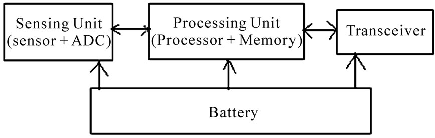
Figure 1. Basic functional units of a sensor node.
may be randomly dropped.
There are certain limitations of the sensor network that restrict the application area of it in the field of explosive detection [4-6]. They are as follows.
1) Power consumption is the most predominant issue in designing a sensor network supporting real time communication as the power supply of a sensor is limited. Also recharging of the battery may not be possible every time. To reduce power consumption different schemes have been proposed by turning off the redundant sensors. So the transmission of sensory data in the sensor network is highly affected by the node failure due to lack of power, physical damage.
2) End-to-end delay, which is the time required for the sensory data to reach from the source node to the base station is another important parameter to support real time and reliable communications. As sensor network uses multi hop routing, if the sensor nodes near to the base station dies then data transmission to the base station will be difficult. Also transmission time of the sensed information depends on the distance of base station from the sensor node that detects the event. So every designed sensor network has an end-to-end delay bound. The real-time performance of the sensor network can be highly improved by guaranteeing soft delay bound.
3) Scalability of the sensor network depends on the transmission range of the sensor and number of sensor nodes used in the network. Depending on the application the density of the sensor nodes may reach from a few hundreds of sensor nodes to few thousand sensor nodes per km. So the cost of the network design will increase if size of the area of deployment increases.
In explosive detection we need very high scalability and fast transmission of sensed information to the base station. An effective mobile sensor network can be designed for explosive detection using the existing cellular network, exploiting cognitive radio [7].
The idea is to embed a tiny sensor node in the mobile phone capable of scanning the surrounding without the knowledge of the user and having the ability to dynamically adapt their communication parameters such as carrier frequency, transmission power and modulation to send the sensory information to the nearest base station. Each cell phone can then be treated as a mobile sensor node for explosive trace detection with the existing base station of the cellular network as the base station for the sensor network. In doing so, the coverage area will not be limited and multihop routing may be avoided as each cell phone can send the sensed information directly to the base station as shown in Figure 2. So the data transmission time must be less than the conventional sensor network. The problem of recharging of the battery of the sensor node can be overcome by using the battery of the
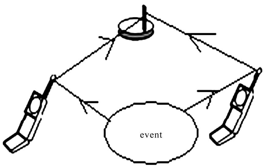
Figure 2. Routing of sensory information from cell phone to base station.
cell phone. The sensor node will also get global mobility which will increase the scalability of the network.
The transreceiver of a conventional sensor node is fully hardware dependent and can transmit and receive the signal of only one radio frequency at a time. For this approach, hardware based tranreceiver may not be fruitful but cognitive radio sensor node (CRSN) will be very effective.
Cognitive radio is a system that can sense the spectrum and determine the vacant bands and use these vacant bands in an opportunistic manner (e.g. more bandwidth, lower error rate, smaller contention delay) [7]. It can operate both in licensed as well as unlicensed band. To realize CRSN, the transreceiver of the sensor node should provide the capability of reconfiguring its operating frequency, modulation, channel coding and output power without hardware replacement. Software-Defined Radio (SDR) or reconfigurable radio system based transreceivers are used for CRSN because of their reconfigurability [8,9]. Here the size of the sensor node is a constraint, as the sensor node has to be embedded in the cell phone.
Most recently, chemical vapor nano sensor systems based on Nano Electrochemical Systems (NEMS) are developed that are used for explosive trace detection in non-conducting mode [10-12]. This type of sensor may be used to design CRSN. The advantages of chemical vapor nano sensor include small size (<100 nm) that miniaturizes the sensor node, less sensing time, low power consumption in the range of mW, re-usability and less idle time between the sensor activities as compared to other sensor types.
The paper is organized as follows. After the introduction an overview of chemical vapor sensor is provided in Section 2. Section 3 deals with the overview of SDR followed by implementation details in Section 4. The paper ends with conclusion in Section 5.
2. Overview of Chemical Vapor Sensor
Chemical vapor sensors are mostly used for explosive trace detection due to their mass scale deployment ability, automatic detection process, low cost, high detection accuracy, high portability, continuous monitoring capability, small size and high reliability as compared to techniques like metal detection and canine [13]. Most commonly used explosives can be divided into six categories based on their chemistry and organic compound which emit certain amount of vapor in air. These are as follows.
1) Organic peroxides, such as triacetone triperoxide (TATP) and hexamethylene triperoxide diamine (HMTD).
2) Nitroaromatic compounds, such as TNT, dinitrobenzene (DNB), hexanitrostilbene, picric acid.
3) Aliphatic nitro compounds, such as nitromethane, hydrazine nitrate.
4) Nitramines or nitrosamines, such as octogen (HMX) or RDX.
5) Nitrate esters, such as pentrite (PETN), ethylene glycol dinitrate (EDGN), nitroglycerine, and nitroguanidine (NQ).
6) Acid salts, such as ammonium nitrate.
Figure 3 shows the maximum vapor concentrations in air of some explosives at room temperature [14]. The figure shows that the home made explosive TATP has very high vapor concentration due to the presence of acetone, a volatile organic compound. Based on this property the explosive vapor sensors are designed, which detect very small amounts of explosive vapor without direct contact with the analyte.
A generalized explosive vapor sensor consists of a transducer and a receptor coating layer as shown in Figure 4 [12]. When the explosive molecules react with the receptor coating layer, an electrical, optical or mechanical signal is generated from the transducer due to the molecular interaction. Sensors that detect analytes by monitoring changes in the resistance are called chemiresistive sensors. The response of chemiresistors to gas concentration is found to follow the following equation [15].
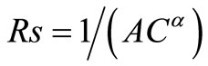 (1)
(1)
In (1) Rs is the resistance of a conducting polymer (receptor coating layer), C is the concentration of a gas molecule and (A, α) are constants that change with the type of gas and temperature of the sensor respectively.
To get a reversible sensor, explosive gas molecule must bind to the receptor with weak molecular interaction like Vander Waals force, electrostatic and hydrogen bonding that can be broken at room temperature.
Chemical selectivity based on weak interaction is poor
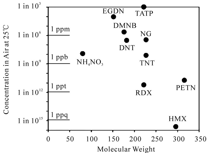
Figure 3. Vapor concentrations of explosives in air at room temperature.
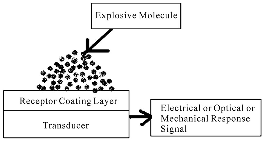
Figure 4. Generalized explosive vapor sensor.
but it can be enhanced by using sensor array with different receptor coating. Sensitivity may be increased by careful design of the receptor.
In this era, chemiresistive sensors using Carbon Nano Tube (CNT) and piezo resistive cantilever beams are the promising technologies to design an explosive vapor sensor. A CNT consists of one or several graphite sheet(s) rolled up into hollow cylinder to form a nano tube [16].
The major classifications of carbon nanotubes are single-walled varieties (SWNTs), which have a single cylindrical wall, and multi-walled varieties (MWNTs), which have cylinders within cylinders as shown in Figure 5. They have diameter of a few nm and length up to 100 μm so that they form extremely thin wires.
Carbon nanotubes have a broad range of electronic, thermal, and structural properties that change depending on different kinds of nanotubes, which are defined by their diameter and length. Figure 6 shows the use of carbon nano tube as electronic wire between two metal electrodes [17]. The conducting properties of the nano tube change when chemicals in the surrounding environment bond to the tube and the conductance between the electrodes may be measured as a function of the gate bias voltage.
The capability of nanotubes to detect small concentrations of gas molecules with high sensitivity at room temperature was found by Kong et al. Sensors made from single-wall nanotubes have high sensitivity and a fast response time at room temperature, which are important advantages for sensing applications.
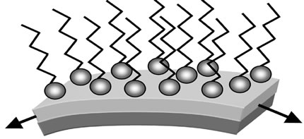
Another approach is nanocantilever sensor arrays which offer a clear path to the development of miniature sensors with very low power consumption. Nano-scale cantilever beams are bent by forces in the range of intermolecular forces [11,18]. When molecular absorption is confined to a single broad surface by applying a suitable coating, the cantilever undergoes bending due to changes in surface stress Due to the large surface-tovolume ratio for these micron-size levers, the bending signal is extremely sensitive and the selectivity is attained by applying chemically selective coatings on cantilevers in an array.
Figure 7(a) shows the schematic cross section of a nanocantilever sensor with a compressive thin film coating at its upper surface and the change of the coating layer stress by the absorption of chemical is shown in Figure 7(b) [12].
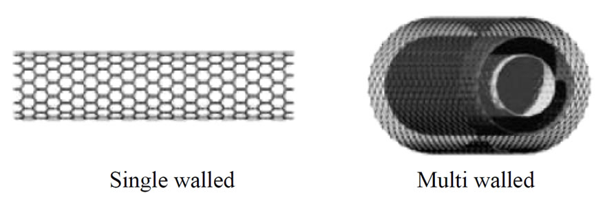
Figure 5. Structure of single-and multi-walled nanotubes.
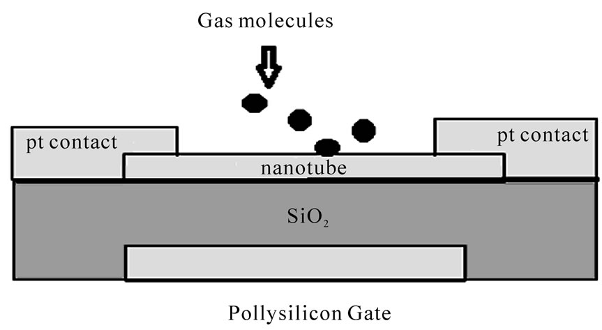
Figure 6. Carbon nanotube used as electronic wire.
 (a)
(a)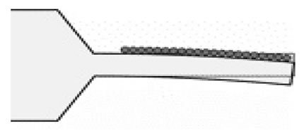 (b)
(b)
Figure 7. Nanocantilever sensor. (a) Schematic cross section of a cantilever with thin film coating on the surface; (b) Change of the coating layer stress of a cantilever by the absorption of chemical.
The deflection z of the cantilevered beam, which is fixed at one end, is determined from the classical beam theory for small deformations and is given by (2) [12].
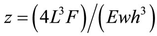 (2)
(2)
Here F is the force applied at the free end perpendicularly to the beam considering rectangular cross section of width w and thickness h with length L and Young’s modulus E.
Different types of transducing principles have been used over the years to convert mechanical displacements into electrical signals. Among them the piezoresistive principle in which the variation in resistivity of a conductor exposed to mechanical stress is converted to electrical signal, is widely used in NEMS/MEMS because this effect is especially strong in semiconductors such as silicon. For this reason piezoresistive cantilever beams are usually fabricated from silicon with length 200 micrometer to a few microns. A resistor is placed on one of its surfaces to detect the deflection of a cantilever, where the mechanical stress is highest. The resistor may be integrated on the bulk material or located on a thin film over its surface. Molecular absorption causes the bending of the cantilever beams that change the resistance of the cantilever.
A cantilever sensor uses four cantilevers: two sensing cantilevers coated with 6-mercaptonicotinic acid (6-MNA) and two referential cantilevers developed in 2007 by Xin Xin Li et al. of Shanghai Institute of Microsystem and Information Technology of China (SIMIT) to detect TNT molecule. They reported that the sensor could detect TNT vapour at the resolution level of several tens of ppt (parts-per-trillion) [10].
Wheatstone Bridge is the most common circuit used to measure response of the resistive sensors. Figure 8 shows the implementation of Wheatstone Bridge by using P type and N type semiconductor nano wires as resistances R1, R2, R3 and R4 [19]. The numerals 101-104 denote low resistance elements which provide low resistance connection between the nano wires. Several nanowires use polymer coating, which amplify the sensory response. Interaction between the coating and the vapor molecules of the chemical induces the P type wires to increase resistance with positive charge and N type wires to decrease the resistance with the same charge. By integrating hundreds of these types of nanoscale sensors on a single chip, an efficient electronic nose can be designed to mimic olfactory systems of mammals.
An electronic nose is usually composed of an array of chemical sensors and a pattern recognition system, such as an artificial neural network to recognize and automatically identify each chemical [20,21] as shown in Figure 9. The array response corresponds to the change in the resistance, Rji(t) (j = 1,  , n, where n = number
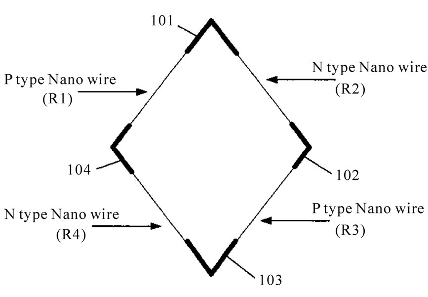
Figure 8. Wheatstone Bridge implementation using nano wires.
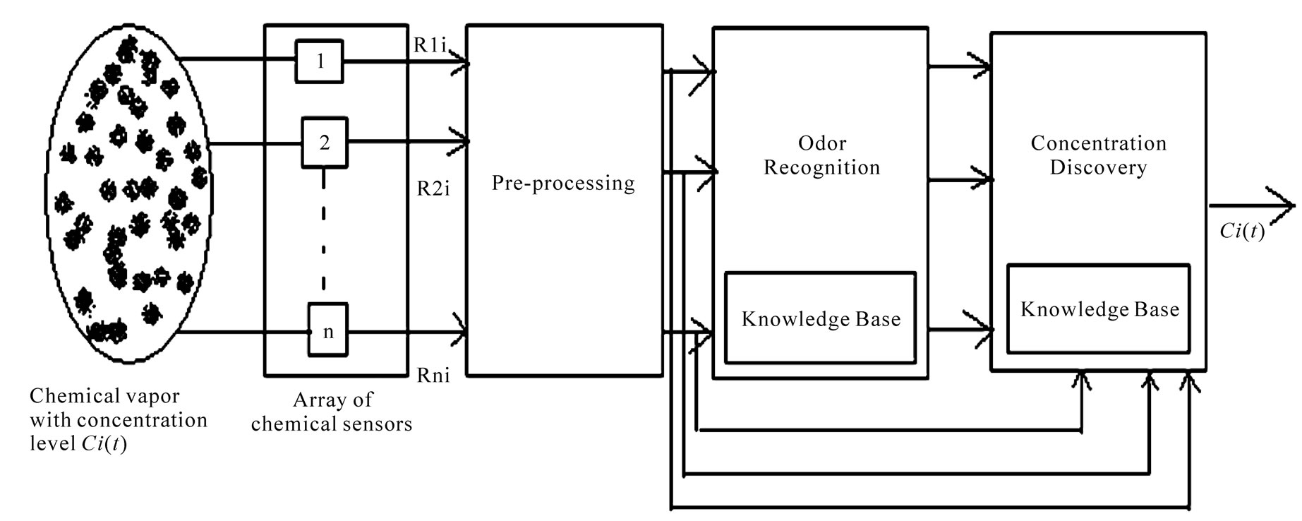
Figure 9. Electronic nose using an array of chemical sensors.
of the sensors) due to the vapor absorption with concentration level Ci as every element of the array is filtered for noise and complexity reduction in order to meet the odor recognition task. This is digitized and the converted signal is then represented by an n-dimensional vector. The pattern recognition system uses the database of the fingerprints produced by different types of vapors to measure their concentration level and subsequently recognize the chemical.
However the design of a single chip nano nose is not so simple and depends on several design parameters viz., fabrication of nanosensor, accurate alignment of the nanosensors with interface circuitry, design of appropriate interface and conversion circuitries and the design of a robust pattern recognition system.
The interface electronics subsystem converts the small analog signals generated by the nano sensor due to deviation in resistances to digital quantities that act as input to the pattern classifier. The nanosensors are positioned above the VLSI circuitry on the epitaxial layer of the CMOS processor using Post-IC placement technique [15]. Sensor placement is considered successful if after final alignment a nanowire provides a resistive bridge— no short or open circuit – across the matting electrodes.
3. Overview of Software-Defined Radio
In radio development one key method is reconfigurability. Reconfigurable receivers include interesting features like automatic recognition of the modulation mode of a received signal or bit stream analysis. A transceiver may be regarded as a software radio (SR) if its communication functions are realized as programs running on a suitable processor [22-24]. SR can be defined as reprogrammable and reconfigurable radio in which same piece of hardware can be used to perform different functions at different times. Based on the same hardware, different transmitter/receiver algorithms, which usually describe transmission standards, are implemented in software. An SR transceiver comprises all the layers of a communication system.
The baseband signal processing of a digital radio (DR) is invariably implemented on a digital processor. The SDR forum defined the SDR as the radio that can accept fully programmable traffic and control information and support a broad range of frequencies air interface and application software. So an SDR may be regarded is a practical version of an SR. Here the received signals are sampled after a suitable band selection filter.
A cognitive radio (CR) on the other hand is an SDR that additionally senses its environment, tracks changes, and reacts upon its findings [9,22]. A CR is an autonomous unit in a communications environment that frequently exchanges information with the networks it is able to access as well as with other CRs.
Traditional communication devices are based on specialized hardware such as transistors and integrated circuits which are designed to deliver a single communication service using a particular standard so a dedicated hardware resources can not be able to support different wireless standards like GSM, GPRS, EDGE, WCDMA, HSDPA, LTE, GPS, mobile TV, Wi-Fi, Bluetooth and UWB. So for supporting a new standard or multiple standards in a single device a new hardware must be added. For this reason it is very expensive to upgrade and maintain a wireless system each time a new standard comes into existence. Figure 10 illustrates a mobile handset supporting both GSM and Bluetooth technologies. However integration of additional radio hardware is impractical after a certain point as it increases the handset size, complexity and price. The attraction of SDR is its ability to support multiple waveforms by re-using the same hardware while changing its parameters in software. This has enormous benefits for handset size, cost, development cycle, upgrade and interoperability. It allows users to change transmitter and receiver characteristics such as modulation type, wideband and narrowband operations, coding and link-layer protocols, radiated power etc., by making software changes without any hardware alternation.In more modern SDRs, digital signal processor (DSP) chips are used that can alter its functionality by executing different software algorithms.
A variety of object oriented programming language like C++, Java may be used for the algorithms. SDR can be implemented in hardware using FPGA, DSP processor or application specific integrated circuit (ASIC). Figure 11 provides a schematic diagram of SDR [25-27].
The RF front-end is used for amplification and filtering because the signal received by the antenna is usually a weak signal and also has the much greater bandwidth than the information bandwidth. A block diagram of a typical frontend is shown in Figure 12. Amplification is gener-
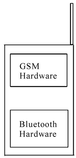
Figure 10. A mobile handset supporting GSM and Bluetooth.
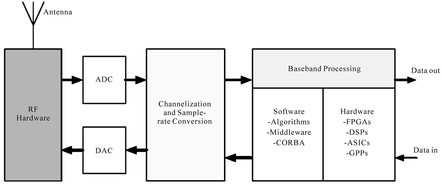
Figure 11. Schematic diagram of a typical SDR.
ally done by low noise amplifier (LNA) and sometimes multi stage amplification is also used. The first band pass filter (BPF) is used for initial filtering and the second BPF is used to decrease the harmonic distortion that may occur during amplification. Mixer stage is used for up conversion in the transmitter and down conversion in the receiver. In SDR the frequency of the mixer is also controlled by the software. In almost all SDR the digitization of the signal is done in the intermediate frequency (IF) range to overcome the problems of carrier offset and imaging involved in digitizing the signal using super-heterodyne method. Channelization and sample rate conversion on the transmit path are used for interfacing the digital hardware to the ADC and ADC to the processing hardware on the received path. In the receiver, the channelizer extracts the channel of interest from the digitized RF bands, and then forwards the channel for baseband processing. In the transmitter it inserts the channel into the RF band after base band processing. The channelization architectures that are widely used in wideband communications systems are Digital Down Conversion (DDC), Frequency Domain Filtering, and Polyphase FFT Filter Banks [28].
Figure 13 illustrates the implementation of a SDR by the U.S. Department of Defenses’ Joint Tactical Radio System (JTRS) [26].
Baseband processing is performed in software using digital signal processors (DSPs), field programmable gate arrays (FPGAs), application specific integrated circuits (ASICs), or general purpose processors (GPPs). The algorithm used to modulate or demodulate signal may use a variety of software methodologies, such as middleware, e.g., common object request broker architecture (CORBA). Here the FPGAs perform the signal processing associated with channelization including fil-
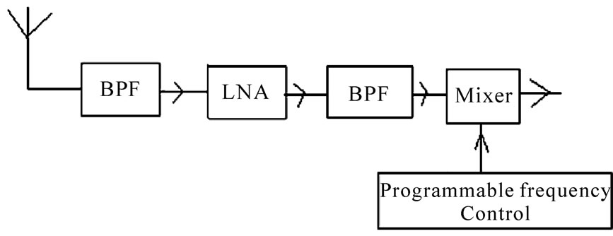
Figure 12. Block diagram of a typical frontend.
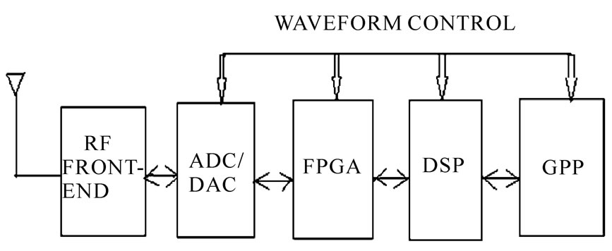
Figure 13. SDR implementation by the U.S. Department of Defenses’ Joint Tactical Radio System.
tering, interpolation, decimation, correlation, Fast Fourier Transforms (FFT), etc and the DSP typically handles the modulation and demodulation. Forward Error Correction (FEC) decode is usually done by a hardware acceleration block in the DSP. The General Purpose Processor (GPP) is responsible for implementing the Medium Access Control (MAC) layer, the JTRS Software Communications Architecture (SCA) and associated CORBA framework, on top of a real-time operating system.
4. Implementation
This section provides a brief outline for the implementation of a mobile sensor network for explosive trace detection using cellular network. The idea is to design a tiny CRSN using a Nano Electronic Nose and integrate it with SDR as shown in Figure 14.
The sensor with SDR consisting of minimum hardware miniaturizes the sensor node. Sensor array will generate an analog signal due to absorption of explosive molecules and for processing the data it is converted to digital signal by ADC.
The processing unit is required to store the data and recognize the explosive using an efficient algorithm. Before transmitting that information, it gathers spectrum usage information through spectrum sensing and then takes a decision about the channel transmission parameters e.g. transmission power, modulation etc. This is called spectrum decision. After that it reconfigures its SDR based transreceiver to send the sensory data to the nearest base station.
In this approach the cell phone user is the primary user with a specific license to communicate over the allocated band and has the priority to access the channel whereas CRSN is the secondary user that can access the channel as long as it does not cause interference to the primary user. It should have the ability to create an ad-hoc network with the other sensor nodes of conventional sensor network to send the data to the place where cell phone tower is not available. The CRSN node should have the ability to switch channel if channel condition gets worse. This functionality is called spectrum handoff. But this can incur long delays. To implement this approach, the main challenge lies in the design of a power efficient and cost effective CRSN which must have the ability of opportunistic communication over licensed as well as unlicensed band maintaining minimum end-to-end delay and interference with the primary user. To achieve this thorough study is required to be done on mobility aware dynamic spectrum management solution over resource constraint CRSN and different methods of adaptive power control to analyze the trade-off between power and interference.
5. Conclusions
In this paper a discussion about SDR and nano nose us-
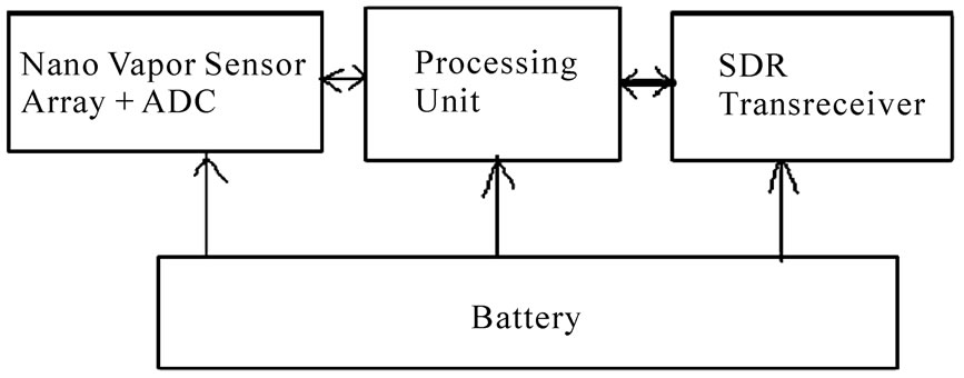
Figure 14. Block diagram representation of sensor based explosive trace detector using SDR.
ing explosive vapor sensor has been made. Investigation of a method for designing a CRSN for explosive trace detection has been carried out. Ultimately an approach towards designing a mobile sensor network utilizing CRSN has been proposed. Out of the total power consumed by the sensor node the major portion is provided by the RF section. So a carefully designed CRSN may be helpful in minimizing the power consumed. This approach is expected to provide real-time situation awareness and decision making with secure information exchange that may help the Department of the Defense and Security of any country to design a network for global security.
6. References
[1] I. F. Akyildiz, W. Su, Y. Sankarasubramanian and E. Cayirci, “Wireless Sensor Network: A Survey,” Computer Networks, Vol. 38, No. 4, 2002, pp. 393-422. doi:10. 1016/S1389-1286(01)00302-4
[2] J. Feng, F. Koushanfar and M. Potkonjak, “Sensor Network Architecture,” In: M. Ilyas and I. Mahgoub, Eds., Handbook of Sensor Networks, Chapter 12, CRC Press, Boca Raton, 2005.
[3] F. L. Lewis, “Wireless Sensor Network,” In: D. J. Cook and S. K. Das, Eds., Smart Environments: Technologies, Protocols, and Application, John Wiley, New York, 2004.
[4] B. Y. Liu and D. Towsley, “A Study of the Coverage of Large-Scale Sensor Networks,” Proceedings of IEEE International Conference on Mobile Ad-hoc and Sensor Systems, Fort Lauderdale, 25-27 October 2004, pp. 475- 483.
[5] A. Koubâa and M. Alves, “A Two-Tiered Architecture for Real-Time Communications in Large-Scale Wireless Sensor Networks,” Proceedings of 17th Euromicro Conference on Real-Time Systems, WiP Session, Palma de Mallorca, 5-7 July 2005, pp. 33-36.
[6] K. Langendoen, “Medium Access Control in Wireless Networks, Volume II: Practice and Standards,” Nova Science Publishers, Hauppauge, 2007.
[7] O. B. Akan, O. B. Karli and O. Ergul, “Cognitive Radio Sensor Networks,” IEEE Network, vol. 23, No. 4, 2009, pp. 34-40. doi:10.1109/MNET.2009.5191144
[8] H. Harada, “Software Defined Radio Prototype toward Cognitive Radio Communication Systems,” Proceedings of 1st IEEE International Symposium on New Frontiers in Dynamic Spectrum Access Networks, Baltimore, vol. 1, 8-11 November 2005, pp. 539-547. doi:10.1109/DYSP AN.2005.1542667
[9] J. Polson, “Cognitive Radio Applications in Software Defined Radios,” Proceedings of the Software Defined Radio Technical Conference and Product Exposition, Phoenix, 15-18 November 2004, pp. 1-24.
[10] D. Y. Kong, Y. G. Qi, L. L. Zhou, B. T. Lin, Z. Li, R. H. Zhu and C. L. Chen, “MEMS Based Sensors for Explosive Detection: Development and Discussion,” Proceedings of 3rd IEEE International Conference on Nano/Micro Engineered and Molecular Systems, Sanya, 6-9 January 2008, pp. 265-269.
[11] L. Senesac and T. G. Thundat, “Nanosensor for Trace Explosive Detection,” Materials Today, Vol. 11, No. 3, March 2008, pp. 28-36. doi:10.1016/S1369-7021(08)700 17-8
[12] J. Bausells, “Microand Nano-Electromechanical Systems for [Bio] Molecular Analysis,” Science, Vol. 3, No. 1, 2005, pp. 67-78.
[13] M. Chakraborty and J. Chakraborty, “Mobile-Telephony Based Secured Society: An Anti Terrorism Attempt,” Proceedings of the International Technical Conference of IEEE Region 10, Hyderabad, 18-21 November 2008, pp. 1-6.
[14] L. Theisan, D. W. Hannum, D. W. Murray and J. E. Parameter, “Survey of Commercially Available Explosive Detection Technologies and Equipment 2004,” 2004, pp. 1-96. http://www.ncjrs.gov/pdffiles1/nij/grants/208861.pdf
[15] K. M. Irick, W. Xu, N. Vijaykrishnan and M. J. Irwin, “A Nanosensor Array-Based VLSI Gas Discriminator,” Proceedings of the 18th International Conference on VLSI Design, with the 4th International Conference on Embedded Systems Design, Kolkata, 3-7 January 2005, pp. 241-246.
[16] R. Khare and S. Bose, “Carbon Nanotube Based Composites—A Review,” Journal of Minerals & Materials Characterization & Engineering, Vol. 4, No. 1, 2005, pp. 31-46.
[17] S. Peng, J. O’Keeffe, C. Y. Wei, K. Cho, J. Kong, R. Chen, N. Franklin and H. Dai, “Carbon Nanotube Chemical and Mechanical Sensors,” Proceedings of 3rd International Workshop on Structural Health Monitoring, San Francisco, 12-14 September 2001, pp. 1-8.
[18] N. R. Frómeta, “Cantilever Biosensors,” Biotecnología Aplicada, Vol. 23, no. 4, 2006, pp. 320-323.
[19] X. F. Yang and K. Peters, “Wheatstone Bridge Scheme For Sensor,” Patent No-US7,009,268 B2, March 2006.
[20] J. Yinon, “Detection of Explosives by Electronic Noses,” Analytical Chemistry, Vol. 75, No. 5, March 2003, pp. 98A-105A. doi:10.1021/ac0312460
[21] M. Grassi, “Wide Dynamic Range CMOS Interface Circuits for Resistive Gas Sensor,” Ph.D. Thesis, Università degli Studi di Pavia, Pavia. http://ims.unipv.it/~marcog/ tesi/final/marco_grassi.pdf
[22] F. K. Jondral, “Software-Defined Radio—Basics and Evolution to Cognitive Radio,” EURASIP Journal on Wireless Communications and Networking, Vol. 2005, No. 3, 2005, pp. 275-283. doi:10.1155/WCN.2005.275
[23] S. Weiss, A. Sligersky, S. Abendroth, J. S. Reeve, L. A. V. Moreau, T. E. Dodgson and D. Babb, “A Software Defined Radio Testbed Implementation,” Proceedings of IEE Colloquium on DSP Enable Radio, 22-23 September 2003, Livingston, pp. 268-274.
[24] E. L. Org, R. J. Cyr, G. Dawe, J. Kilpatrick and T. Counihan, “Software Defined Radio—Different Architectures for Different Applications,” Proceedings of the Software Defined Radio Technical Conference and Product Exposition, Denver, 5-9 November 2007, pp. 1-5.
[25] L. S. Nagurney, “Software Defined Radio in the Electrical and Computer Engineering Curriculum,” Proceedings of 39th ASEE/IEEE Frontiers in Education Conference, San Antonio, 18-21 October 2009, pp. 1-6.
[26] N. Bagherzadeh and T. Eichenberg, “Mobile Software Defined Radio Solution Using High Performance, LowPower Reconfigurable DSP Architecture,” Proceedings of the Software Defined Radio Technical Conference and Product Exposition, Orange County, 14-18 November 2005, pp. 1-5.
[27] Y. F. Li, Z. T. He and T. Voigt, “A Software Radio-Empowered Sensor Network,” Proceedings of 9th Scandinavian Workshop on Wireless Ad Hoc Networks, Uppsala, 4-5 May 2009, pp. 1-3. http://soda.swedish-ict. se/3607/1/sncnw09-sdr-demo.pdf
[28] L. Pucker, “Channelization Techniques for Software Defined Radio,” Proceedings of SDR Forum Conference, Orlando, 17-19 November 2003, pp. 1-6. http://www. spectrumsignal.com/channel_techniques/channelization_ paper_sdr_forum.pdf